manuals.online logo
Brands
  1. Home
  2. •
  3. Brands
  4. •
  5. Craftsman
  6. •
  7. Tiller
  8. •
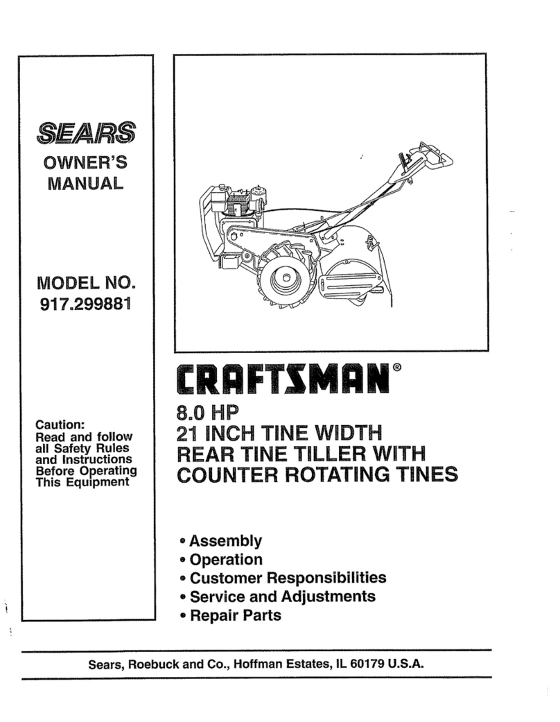
  9. Craftsman 917.292040 User manual

Craftsman 917.292040 User manual

Other Craftsman Tiller manuals

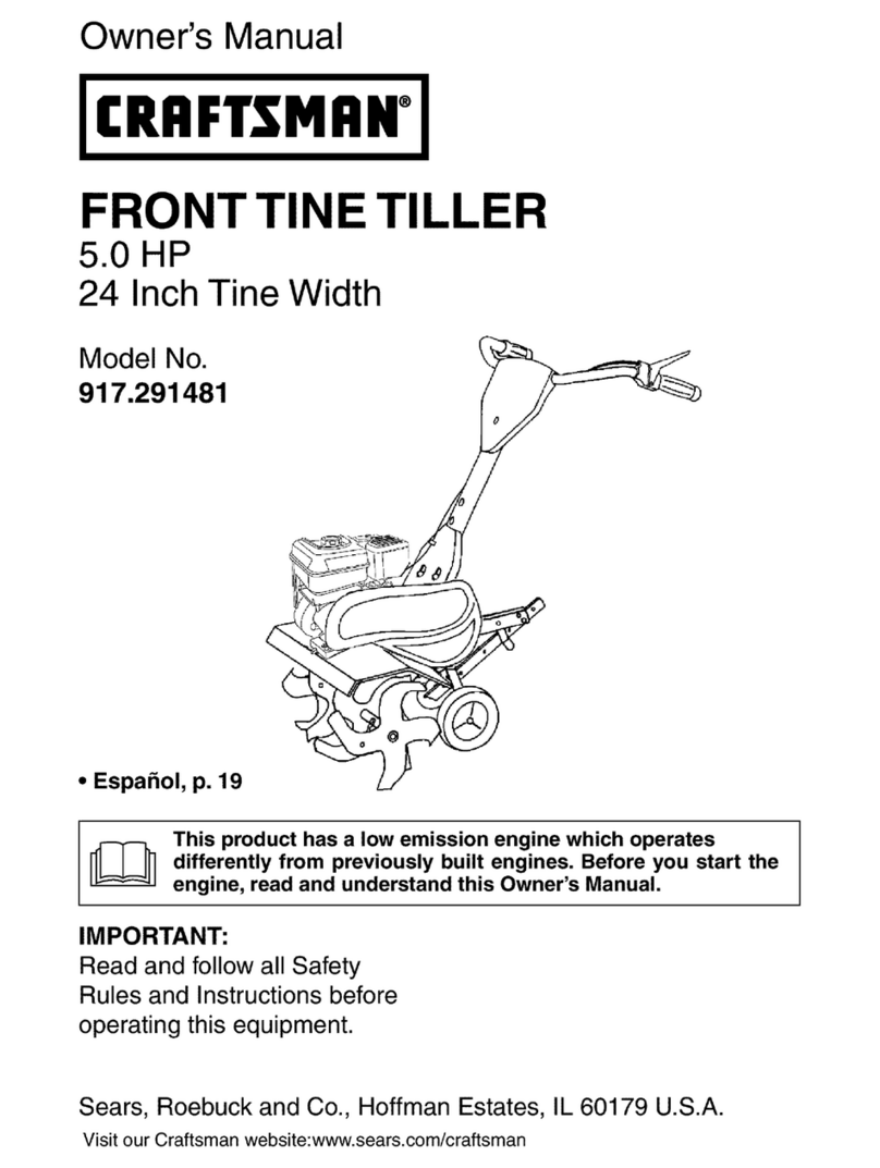
Craftsman 917.291480 User manual

Craftsman

Craftsman 917.291480 User manual

Craftsman 917.293483 User manual

Craftsman

Craftsman 917.293483 User manual

Craftsman 917.293550 User manual

Craftsman

Craftsman 917.293550 User manual

Craftsman 917.297031 User manual

Craftsman

Craftsman 917.297031 User manual

Craftsman 247.23000 User manual

Craftsman

Craftsman 247.23000 User manual

Craftsman 917.988940 User manual

Craftsman

Craftsman 917.988940 User manual

Craftsman 29286 User manual

Craftsman

Craftsman 29286 User manual

Craftsman 536.292521 User manual

Craftsman

Craftsman 536.292521 User manual

Craftsman 917.292360 User manual

Craftsman

Craftsman 917.292360 User manual

Craftsman 247.29934 User manual

Craftsman

Craftsman 247.29934 User manual

Craftsman 486.252442 User manual

Craftsman

Craftsman 486.252442 User manual

Craftsman 917.291490 User manual

Craftsman

Craftsman 917.291490 User manual

Craftsman 917.29249 User manual

Craftsman

Craftsman 917.29249 User manual

Craftsman 917.297020 User manual

Craftsman

Craftsman 917.297020 User manual

Craftsman 917.293321 User manual

Craftsman

Craftsman 917.293321 User manual

Craftsman 917.293302 User manual

Craftsman

Craftsman 917.293302 User manual

Craftsman 944.629541 User manual

Craftsman

Craftsman 944.629541 User manual

Craftsman 316.2927 User manual

Craftsman

Craftsman 316.2927 User manual

Craftsman 316.292601 User manual

Craftsman

Craftsman 316.292601 User manual

Craftsman 944.629672 User manual

Craftsman

Craftsman 944.629672 User manual

Craftsman 917.294480 User manual

Craftsman

Craftsman 917.294480 User manual

Craftsman C459.62103-1 User manual

Craftsman

Craftsman C459.62103-1 User manual

Craftsman 247.29932 User manual

Craftsman

Craftsman 247.29932 User manual

Craftsman 917-299751 User manual

Craftsman

Craftsman 917-299751 User manual

Popular Tiller manuals by other brands

WIL-RICH 2500 Operator's manual

WIL-RICH

WIL-RICH 2500 Operator's manual

MTD 410R parts list

MTD

MTD 410R parts list

Viking HB 685 instruction manual

Viking

Viking HB 685 instruction manual

SMASH TLG415 instruction manual

SMASH

SMASH TLG415 instruction manual

FarmBoy FB-IC-209P user manual

FarmBoy

FarmBoy FB-IC-209P user manual

MTD FRT Series Operator's manual

MTD

MTD FRT Series Operator's manual

Troy-Bilt Colt FT Operator's manual

Troy-Bilt

Troy-Bilt Colt FT Operator's manual

MTD OHV Series Original operating instructions

MTD

MTD OHV Series Original operating instructions

YAT YT5601-01 Assembly, Use, Maintenance Manual

YAT

YAT YT5601-01 Assembly, Use, Maintenance Manual

Scheppach MTP560 Translation from the original instruction manual

Scheppach

Scheppach MTP560 Translation from the original instruction manual

GARDEN WAY 12194 owner's manual

GARDEN WAY

GARDEN WAY 12194 owner's manual

Classen STAND-AER SA-25 Operator's manual and parts list

Classen

Classen STAND-AER SA-25 Operator's manual and parts list

Altrad ATIKA BH 1400 N Original instructions, safety instructions, spare parts

Altrad

Altrad ATIKA BH 1400 N Original instructions, safety instructions, spare parts

DR PILOT 2 Safety & Operating Instructions

DR

DR PILOT 2 Safety & Operating Instructions

AL-KO TL 1820 Instructions for use

AL-KO

AL-KO TL 1820 Instructions for use

breviglieri mekfarmer 120 Operating and maintenance

breviglieri

breviglieri mekfarmer 120 Operating and maintenance

Troy-Bilt 769-03618 Operator's manual

Troy-Bilt

Troy-Bilt 769-03618 Operator's manual

SNOWJOE SUNJOE TJ602E-RM Operator's manual

SNOWJOE

SNOWJOE SUNJOE TJ602E-RM Operator's manual

manuals.online logo
manuals.online logoBrands
  • About & Mission
  • Contact us
  • Privacy Policy
  • Terms and Conditions

Copyright 2025 Manuals.Online. All Rights Reserved.

CRAFTXMANo
/ -29204
Instruction manual
Please read these instructions
carefully and make sure you under-
stand them before using this machine.
Anleitungshandbuch
Bitte lesen Sie diese Anteitungen
sorgf&ltig durch und vergewissem Sie
sich, dab Sie diese verstehen, bevor
Sie die Maschine in Betrieb nehmen.
Manuel d'instructions
S'il vous plait lisez soigneusement et
soyez s_r de comprende ces
instructions avant d'utiliser cette
machine.
Manual de las instrucciones
Por favor lea cuidadosamente y
comprenda estas intrucciones antes
de usar esta maquina.
Manuale di istruzioni
Prima di utilizzare la macchina leggete
queste istruzioni con attenzione ed
accertatevi di averle comprese bene.
Instructieboekje
Lees deze instructies aandachtig en
zorg ciat u ze begrijpt voordat u deze
machine gebruikt.
IMPORTANT!
Read operating instructionscarefully before starting the
engine. Remember to filloil inthe engine crankcase
before commencing.
Contents Page
1. Safety precautions 4
2. Assembly Instructions 8
3, Start and Operation 21
4. Maintenance 43
After use
Storage
Lubrication Chart
Regularly
Annual (end of season)
5. Repair and Adjustments 53
Changing be_ts
Tine Replacement
6. Troubleshooting 65
7. Technical data 68
(_ WICHTIG!
Lesen Sie die Gebrauchsanleitung genau, bevor Sie die
Motorhacke in Gebrauch nehmen Ffillen Sie _1in den
Mottorraum.
Inhaltsverzeichnis Seite
1. Sicherheitsregeln 4
2. Montageanleltung 8
3. Start und Betrieb 21
4, Wartung 43
Nach Arbeitsschluss
Aufbewahrung
Schmierplan
Regelm&ssig
J&hrlich (nach jeder Saison)
5. Reparatur und Einstellung 53
Keilriemenwechsel
Auswechseln der Zinken
6. Fehlersuche 65
7. Techinsche Daten 68
(_ IMPORTANT!
Ne pas mettre le motoculteur en route avant D'avoir lu la
presente notice.
Faire leplein d'huiie
Table des matieres Page
1. R_gles de sdcur|td
BELANGRIJK!
Lees de gebruiksaanwijzing nauwkeurig voordat ude
freesmachine start.
Vergeet niet de o_iebijte vullen.
Inhound Pag.
5 1. Veiligheidsvoorschlften 5
2. Instructions de montage 8
3. Mise en marche et conduite 21
4. Entretien 43
Apr_s utilisation
RangerP_nt
Plan de graissage
A intervalles regulieres
Annullement (&lafine de chaque saison)
5. Rdparations et rdglages 53
Changement de _acourroie
Changement des dents
6. Recherche des pannes 65
7. Donn_es techniqes 68
2. Montage-aanwijzingen 8
3. Starten en rijden 21
4. Onderhoud 43
Nagebruik
Opslaan
Smeerschema
Reglematig
Jaarlijks (aan ende van seizoen)
5. Herstellen en afstellen 53
Riem vervangen
TandVervangen
6. Schema voor het zoeken van fouten 65
7. Technische gegerens 68
2
_) 1. SAFETY RULES
TRAINING
•Read the instructions carefully. Be familiar with the controls and the
proper use of the equipment;
•Never aUowchildren or people unfamiliar with these instructions to use
the machine. Local regulations can restrict the age of the operator.
Never work while people especially children, or pets are nearby.
:Keep in mind that the operator or user is responsible for accidents or
hazards occurring to other people or their property.
PREPARATION
• While working, always wear substantial footwear and long trousers.
Do notoperate the equipment when barefoot or wearing open sandals.
•Thoroughly inspect the area were the equipment is to be used and
remove all objects which can be thrown by the machine.
WARNING: Petrol is highly _ammable:
-store fuel in containers specifically designed for this purpose;
- refuel outdoors only and do not smokewhile
refueling;
-add fuel before starting the engine. Never remove the cap of
the fuel tank or add potrol while the engine is running or when
the engine is hot;
-if petrol is spilled, do not attempt to start the engine but
move the machine away from the area of spillage and
avoid creating any source of ignition until petrol vapors
have dissipated_
-replace all fuel tank and container caps securely.
•Replace faulty silencers.
•Before using, always visually inspect to soo that the tools are not wom
or damaged. Replace wom or damaged elements and bolts in sets to
preserve balance.
OPERATION
•Do not operate the engine in a confined space where dangerous
carbon monoxide fumes can collect.
0o not change the engine governor settings or overspoed the engine.
Work onty in daylight or in good artificial light.
Always be sure of your footing on slopes.
Walk, never run.
•For wheeled rotary machines, work across the slopes, never up and
down.
•Exercise extreme caution when changing direction on slopos.
•Do not work on excessively steep slopes.
•Use extreme caution when reversing or puFlingthe machine towards
V_ou.
• _)o not run the engine indoors; exhaust fumes are dangerous.
• Start the engine carstul_ according to _ns_ructloos and w_thfeet well
away from the tool(s).
Do not put hands or feet near or under rotating parts.
•" Never pick up or carry a machine while the engine is running.
•Stop the engine:
-whenever you _eave the machine ar_l before re_elUeg.
•Reduce the throttle setting during engine shut down and, ifthe engine
is provided with a shut-off valve, tum the fuel off at the conclusion of
working.
MAINTENANCE AND STORAGE
•Koop all nuts, belts and screws tight to ensure the equiprnent is in safe
working condition.
•Neverstoretheequipmentwithpetrolinthetankinsideabuildingwhera
fumes can reach an open flame or spark.
•Allow the engine to cool before storing in any enclosure.
•To reduce the fire hazard, keep the engine, silencer, battery compart-
rnent and petrol storage area free of vegetative material and excessive
grease.
_placo worn or damaged parts for safety.
•If the fuel tank has to be drained, this should be done outdoors.
(_ 1, SICH ERH EITSVORSCHRIFTEN
SCHULUNG
•Die Aoleltungen grOndlich durchlesen. Bitte machen Sie sich mit den
Bedienungselementen und dem ordnungsgen_Ben Gebrauch der
Maschine vertraut.
•Auf keinoo Fall Kindem oder Personen, die nicht mit dlesen Anleitungen
vertraut sind, den Gebrauch dieser Masehine gestatten.
M6glicherweise wird des Mindestalter per Bedienungsperson dureh
6rtliche Vorschriften bestimmti
•Auf keinen Fall in der N_he von anderen Personen, insbesondere
Kindem oder Haustleren arbeiten.
•Daran denken, dab die Bedienungsporson oder der Besitzer f_3r
Unf&lle oder Gefahren haftet, denen andere Personen oder deren
Eigentum ausgesetzt werden.
VORBEREITUNG
•Set der Arbeit immer festes Schuhwerk und lange Hosen tragen. Die
Maschine nicht bartul_ oder in offenen Sandaloo betraiben.
•Den Arbeitsbereich, in dem die Maschine betrieben werden sol1,
sorgf_,ltiguntersuchen und alle Gegenst&nde, die durch die Maschine
geschleudert werden k_nnten, entfernen.
WARNUNG: Benzin ist _uBerst leicht entzDndlich:
- Kraftstoff in besonders dati3rvorgesehenen Bah&Item legem.
-Nur im Fralen tanken und w&hrend des Tankens nleht
rauehen.
-Kraffstoff einf01len, bevor der Motor angelassen wird. Den
Tankdeckel nicht enffemen und kein Senzin nachfGllen,
solange der Motor I_,alt oder hell3 ist.
-Falls Benzin verschOttet wird, nicht versuchen, den Motor
anzulassen, sondern die Maschine vom verschSttetan Ben-
zin enffemen und versuchen, jegliche Funkenbildung zu
vermeiden, bis s&mtliche Benzind&mpfe sich vertl0chtigt
haben.
- Die Deckel des Benzintanks und des Benzinbeh_lters sicher
aufschrauben.
•Sehadhafte Schalld&mpfer ersetzen.
•Vor dem Gebrauch immer eine SichtprOfung durchfOhren, um
sicheFzustellen, dal3 des Werkzeug nicht abgenutzt oder besch&digt
ist. Abgenutzte oder schadhafte Teile und Schrauben als vollst&ndigen
Satz ersetzoo, um die Auswuchtung beizubehalten.
BETRIEB
•Den Motor nicht in einem engen Berelch betreiben, indem sich giftiges
Kohlenmonoxid ansammeln k(3nnte.
•Keine &nderungen an den einstellungen des drehzahlreglers vomehmen
und den motor n_cht mit zu hohen drehzahlen betreiben.
•Nur bet Tageslicht oder guter k0nstlicher Beleuchtung arbeiten.
• Auf Abh&ngen immer auf sicheren Stand achten.
•Gehen, nicht rennen.
•Bet Drehfr&sen mit R_.dem entlang von Abh&ngen arbeiten, nicht
bergauf und pergab.
Beim Richtungsweshsel auf Abh_ngen ist besondere Vorsicht geboten.
iieht auf Qberrn&Big steiloo Abh&ngen arbeiten.
Beim Umkehren oder Zlehen der Maschine in die eigene Richfung
besonders vorsichtig vorgehen.
Den Motor nur im Freien betreiben; die Auspuffgase sind glttig.
Den Motor vorsichtig und den Anlaltungen gern_13anlassen. Die FORe
immer in sicherem Abstand haiten.
•Die F013eund H_nde nicht in die N&he yon oder unter drehende Teile
bringen.
•Die Maschine auf keinen Fall anheben oder tragen solange der Motor
I_uft
•Den Motor abstellen:
-wenn die Maschine vedassen wird und bevor getankt wird.
•Beim Abstellen des Motors dieGaseinstellung raduzleren und, falls der
Motor _per einen Kraftstoffhahn verfOgt,des Benzin zu Ende der Arbeit
abschalten.
WARTUNG UND LAGERUNG
•Alte Muttam, Bolzen und Schrauben fest angezogen lessen, um
sicherzustellen, dab die Maschine sich in sicherem Betriebszustand
bef_P_et.
•Die Maschine nicht mlt Senzin im Tank in einem Geb&ude lagem, in
dem die Benzind_mpfe mit offenem Feuer oder Funken in Ben3hrung
kommen k_nnen.
Den Motor vor der Lagerung in einer Abdeckung abkDhlen tassen.
:Um die Brandgefahr zu reduzleren, den Motor, Schalld_'npfer, das
Satterieabteil und den Lagerungsbereich for das Benzin yon
Pflanzenteilen und 0berm&P_igem _chmierfett fret halten.
• AbgenutzteoderschadhalteTeilesindsicherheitshatberzuersetzen.
•FallsderBenzintankentloortwerdenmul3, solltediesimFrelengetan
werden.
4
_)These symbols may appear on your unit or in the literature
supplied with the product. Learn and understand their
meaning
(_)Diese Symbole finden Sie aur ihrer Maschine order in
Utedagen, die mit dem Produkt ausgeh&ndigt wurden. Bitte
machen Sie sich mit deren Bedeutung vertraut.
(_Cez symbotes peuvent se mountrer sur votre tracteur ou
dans les publications foumies avec le produit. Apprenez et
comprenez la signification des symboles.
(_)Deze symbolen kunnen op uw machine of in de bij hetproduct
geleverde documentatie aanwezig zijn. Leer en begrijp
hum betekenis.
(_) Estos simbolos pueden apareier sobre su unidad o en la
literatura prodprcionada con el producto. Aprenda y
comprenda sus significados.
(_) Simboli sull'apparato o nella
utilizzati faciante
documentzione fornita con il prodotto. E' importante
cononscerne bene il significato,
(_L&r k&nna dem och deras innebSrd.
Symbolene ber la_res slik at du kan forst& hva de betyr.
Deter vigtigt at laere og forst& deres betydning, Opi
ymm&rt&m&&n niiden merkitys.
,NIF F
F N R
TILLING FORWARD NEUTRAL REVERSE FAST
RODENFRASEN VORWARTSGANG LEERLAUF ROCKWARTSGANG SCHNELL
FRAISAGE MARCHE EN AVANT POINT MORT MARCHE ARRli:RE RAPIDE
VOORWAARTS VOORUIT VRIJLOOP ACHTERUIT SNEL
LABOREO MARCHA HACIA NEUTRO REVES RAPIDO
ARATURA DELANTE FOLLE RETROMARCIA VELOCE
FR/_$NING MARCIA NEUTRAL BACK SNABB
DYRKING FRAMAT FRI REVERS HURTIG
FR_ESNING FRAMOVER FRIGEAR BAKGEAR HURTIG
JYRSINT_, FREMAD VAPAAVAIHDE PERUUTUS NOPEA
ETEENPAIN
KEEP BYSTANDERS AWAY
ZUSCHAUER FERNHALTEN
GARDEZ LES SPEGTATEURS
LOIN DE VOUS
OMSTANDERS UIT DE
BUURT HOUDEN
GUARDESE LEJOS DE GENTE
TENERE LONTANI I PASSANTI
SE TILL ArT ASKADARE
BEFINNER SIG PA BEHORIGT
AVST_ND
UVEDKOMMENDE PERSONER
BOR HOLDES BORTE
HOLD TILSTEDEVAERENDE
P_ AFSTAND
PIDA OHIKULKIJAT POIS
I.AHEI"rYVILT,_
READ OWNERS MANUAL
BETRIEB_ANLEITUNG LESEN
LISEZ LE MANUEL DU
PROPRIETAIRE
GEBRUIKERSHANDLEIDING
LEZEN
LEA EL MANUAL DEDUEI_IO
LEGGERE IL MANUALE
DELL'OPERATORE
I._S ANVANDARHANDBOKEN
LESBRUKSANVISNINGENE
LAESBETJENINGSVEJLEDNINGEN
LUE OMISTAJAN OHJEKIRJA
6
SLOW ENGINE OFF
LANGSAM MOTOR AUS
LENTE MOTEUR ARRPrE
LANGZAAM MOTOR UIT
LENTO MOTOR APAGADO
LENTO MOTORE SPENTO
I_NGSAM MOTORN AV
LANGSOM MOTORN AV
LANGSOM MOTOR STANDSET
HIDAS MOOITORI POIS
PAALLT/_
%
EUROPEAN MACHINERY
DIRECTIVE FOR SAFETY
EUROPAISCHE VERORDNUNG
FOR MASCHINEN-SICHERHEIT
DIRECTIVE POUR LA SI:tCURITE
DE MACHINE EUROPEEN
VEILIGHEIDSRICHTUJN VOOR
EUROPESE MACHINES
DIRECTIVO DE MAQUINARIA
EUROPEO PARA LA SEGURIDAD
NORMATIVE ANTINFORTUNISTICHE
EUROPEE PER MACCHINARI
EUROPEISK STANDARD
FOR MASKINS/_KERHET
EUROPEISKE
MASKINSIKKERHETSREGLER
EU'S MASKINDIREKTIV
FOR SIKKERHED
EUROOPPALAINEN
WARNING
•"_. WARNUNG
AVERTISSEMENT
WAARSCHUWlNG
ATENCION
AVVERTENZA
VARNING
ADVARSEL
ADVARSEL
VAROITUS
KONETURVADIREKTIIVI
HAND PLACEMENT
HAND HIER AUFLEGEN
PLACEMENT DE MAIN
PLAATSING VAN DE HANDEN
POSICll6N DE LA MANO
PO_ZIONE MANI
HANDPLASSERING
SADAN HOLDER MAN PA
REDSKABET
KADEN ASENTO
a
CHOKE FUEL CAUTION WARNING
STARTKLAPPE KRAFTSTOFF VORSICHT WARNUNG
STARTER ESSENCE A3-rENTION AVERTISSEMENT
CHOKE BRANDSTOF OPGELET WAARSCHUWING
ESTRANGULACI()N COMBUSTIBLE PRECAUClON ATENClC)N
STARTER CARBURANTE ATfENZIONE AVVERTENZA
CHOKE BRANSLE VIKTIGT VARNING
CHOKE BRENSEL FORSIKTIG ADVARSEL
CHOKER BRAENDSTOF FORSIGTIG ADVARSEL
RIKASTIN POLI-rOAINE VARO VAROITUS
CLUTCH CONTROLS
KUPPLUNGSBEDIENUNG
COMMADE D'EMBRAYAGE
KOPPELBEDIENING
CONTROL DEL EMBRAGUE
COMANDO FRIZIONE
CLUTCH KONTROLL
KOBINGSGREB
KYTKINVIPU
7
2. Assembly instructions 2. Montageanleitung
2. Instructions de montage 2. Montage-aanwijzingen
2. Montaggio 2. Instrucciones de montaje
(_ 1. Gearcase notch
2. Handle lock
3. Handle (high position)
4. Shift lever
5. Handle (low position)
6. Handle lock lever
Figure 1
Install handle
a. Insert one handle lock (with teeth facing outward) in
gearcase notch (fig. 1). Apply grease on smooth side of
handle lock. This will aid in keeping lock in place until
handle is lowered into postion.
b, Grasp handle assembly, ease handle base into "up"
position as shown in figure 2. Be sure handle lock
remains in gearcase notch. Be careful notto stretch or
kink cables.
c. Rotate handle assembly down. Insert rear carriage bolt
(fig. 3-inset) first, with head of bolt on L.H. side of tiller.
Insert front pivot bolt. Lower the handle assembly.
Tighten bolts so handle moves with some resistance.
d. Insert second handle lock (with teeth facing inward) in
slot handle base (fig. 3-inset).
e. Place washer on threaded end of handle lock lever.
f. Insert handle lock lever through handle base and gear
case (fig. 3-inset).
g. With handle assembly in lowest position, securely tighten
handle lock lever by rotating clockwise.
Figure 2
5
8
2
@1. Shift rod
2. Hairpin clip
3. Shift lever indicator
4. Handle assembly
5. Carriage bolt and Iocknut
Connect shift rod
a. Insert end of shift rod into hole of shift lever indicator.
b. insert hairpin clip through hole of shift rod to secure.
Connect clutch cable
Connect clutch cable to control bar bracket as shown (fig. 4).
6. Handle base
7. Slot
8. Greasecase
9. Handle lock
10. Washer
11. Handle lock lever
12. Pivot bolt
Figure 323
Tire pressure
Reduce tire pressure to 20 PSI (Tires were overinflated for
shipping purposes), If tire pressures are not equal, tiller will
pull to one side,
Inset
45
11
12
Figure 4
9
2
(_1. Handle Bar
2. Throttle control
3. Shift lever
4. Drive control bar
5. Tine shield
6. Engine
7. Wheel
8. Model plate
(_1. Guidon
2. Accelerateur
3. Levier de changement de
vitesse
4. Barre de commande
5. Protection des dents
6. Moteur
7. Roue
8. Palque d'identification
(_1. Manubrio
2. Comando del gas
3. Leva del cambio
4. Leva de avanzamento
5. Disco salvapiante
6. Motore
7. Route
8. Traghetta di indentificazione
_)1. Handgriff
2. Gashebel
3. Schalthebel
4. Antriebshebel
5. Zinkenschutz
6. Motor
7. R&der
8. Typenschild
_)1. Hendel
2. Gashendel
3. Schakelhendel
4. Stuurhendel
5. Tandbeschermplaat
6. Motor
7. Wiel
8. Modelplaatje
(_1. Guia
2. Mando de aceleracibn
3. Palanca de cambio
4. Barra de control de propulsibn
5. Cubierta protectora de dientes
6. Motor
7. Rueda
8. Chapa de modelo
4 2

I
©
20
3. Start and Operation 3. Start und Betrieb
3. Mise en marche et conduite 3. Starten en rijden
3. Aviamento e guida 3. Arranque y cinducci6n
(_ 1. Oil level
2. Oil filler plug
(_) NOTE!
Before operating your tiller for the first time, study this section
and the "1. Safety instructions".
®
3. Fuel tank cap
1. Olstand
2. Oleinf011schraube
Check engine oil level
a. With engine level, remove engine oil filler plug (fig. 5)
b. Engine oil should be to point ofalmost overflowing (fig.
5). Engine oil capacity is about 1 1/4 pints (20 ounces).
3. Tankdeckel
Figure 5
Abb. 5
J
Figure 6
Abb. 6
3
I--
©
2
NOTE!
Be very careful not to allow dirt to enter the Engine when
checking or adding oil or fuel. Use clean 30 or t 0W-30 grade
oil and store in approved, clean covered containers. (Do not
use pressurized starting fluid, as severe internal engine
damage may occur due to loss of lubrication.)
Fill fuel tank
To fill fuel tank (fig. 6), use fresh, clean regular unleaded
automotive gasoline. Capacity is about 2.5 quarts.
(_ ACHTUNGt
Vor tier ersten Inbetriebnahme der Bodenfr&se sind die
folgenden Punkte und "1. Sicherheitsvorschriften".
Olstand im Motor Kontroliieren
a. Bei niedrigem Motor_tstand 61einf_llschraube
herausschrauben (Abb. 5).
b. Das Motor61 solte am Einf_llstutzen fast Obedaufen
(Abb. 5). Die Motor61menge betr&gt ca. 0,6 1.
ACHTUNG!
Beim Kontrollieren oder auff011endes MomrOls, istdarauf zu
achten, dab kein Schmutz in den Motor gelangt. Es ist
sauberes 30 oder 10W-30 Motor61 zu verwenden und in
geeigneten, sauberen Kanistem zu verwahren. (Keine
unter Druck stehende Startfl_ssigkeit verwenden, da
mangelhafte Schmierung schwere Motorsch&den
verursachen kann).
KraftstofftankauffOllen
Zum Auff.".llendes Tanks (Abb. 6) ist sauberes, unve_leites
Normalbenzin zu verwended. Tankinhalt ca. 3 1.
21
3
(_) 1. Starter handle
2. Choke lever
3. Spark plug wire and cover
4. Shift lever indicator
5. Drive control bar "disengaged" position
6. Drive control bar "engaged" position
7. Throttle control
8. Handle grip
Figure 7
3
--"-"--2
Figure 8
4
Starting the engine
a. Reconnect spark plug wire and cover (fig. 7),
b, Move shift lever indicatorto"N" (neutral) position (fig. 8). •
c. Place throttle control (fig. 9) in "FAST" position.
d. Place choke lever in "CHOKE" position (fig. 7).
e, Grasp starter handle (fig. 7) with one hand and grasp
handle bar with other hand, Pull rope out slowly until
engine reaches start ofcompression cycle (rope willpull
slightly harder at this point).
f. Pull rope with a rapid, continous, full arm stroke. Keep
a firm grip on the starter handle and let rope rewind
slowly. Do not let starter handle snap back against
starter.
g. Repeat steps (e.) and (f.) until engine starts. When
engine starts. Place choke lever on engine halfway
between "CHOKE" and "RUN" position (fig. 7) and then
move to "RUN" position as engine warms up.
h. Move throttle control (fig. 9) halfway between "FAST"
and "STOP" position for a few minutes to warm up.
_, WARNING!
Keep drive control bar in "disengaged" position when
starting the engine (fig, 9).
NOTE!
In order to idle smoothly, a new engine may require 3 to 5
minutes runnig time above slow idle speed. Idle speed has
been adjusted to be correct after this break-in period.
Tine operation
a. Move throttle control to desired speed.
b, Tine movement begins when drive control bar is in
•engaged" position (fig. 9),
WARNING!
Always release drive control bar before moving shift lever
into another position.
Figure 9
24
3
5
Inset A
Inset B
Figure
10
7
8
Figure
11
12-""--
13_
14...-.._
16 inset C
1. Outer side shield
2. Nut "A"
3. Nut"B"
4. Drive control bar
5. Handle
6. Throttle control
10. Transport position
11. Shallowest tilling
12. Shallow tilling
13. Deep tilling
14. Deepest tilling
15. Depth stake
(_) Reverse
a. Release the drive control bar (fig. 10).
b. Move throttle control (fig. 10) to "SLOW" speed
c. Place shift lever indicator _fig. 11 -inset A) in the "R"
(reverse) posffion.
d. Do not stand directly behind tiller.
e, Hold the ddve control bar against the handle (fig. 10) to
start tiller movement. Tines will not turn.
_ll WARNING!
Don't back yourself into asolid obstruction such as a tree,
fence, etc.
Stopping tines and engine
a. Tiller movement and tines will stop when drive control
bar (fig. 10) is released.
b. Move shift leverindicator (fig. 11 -inset A)to"N" (Neutral)
position.
c. To stop engine, move throttle control (fig. 10) to "STOP"
position.
Turning
a. Re_ease the drive controlbar (fig. 10).
b. Move throttle control (fig. 10) to "SLOW" position.
c. Placeshiftleverindicator(fig,11 -insetA) in"F"(forward)
position. Tines will not turn.
d. Lift handle to raise tines out of the ground (fig. 10)
e. Swing the handle in the opposite direction you wish to
turn, being careful to keep feet and legs away from the
tines.
When you have completed your turn-around, lower the
handle. Place shift lever indicator in "T" (tilling) position and
move throttle control to desired speed. To begin tilling, hold
drive control bar against the handle.
Outer side shields
The back of the outer side shields (fig, 1O)are slotted so that
they can be raised for deep tilling and lowered for shallow
tiltingto protect small plants from being buried. Loosen nut
'A" in slot and nut "B". Move shield to desired position (both
sides). Retighten nuts.
Transporting
e. Lower the depth stake to its lowest position and insert
the depth stake pin in the t_amost hole.
b. Place shift lever indicator (fig. 11 inset A) in "F" (foward)
position for transporting.
c. Hold the ddve control bar against the handle (fig. 10) to
start tiller movement. Tines will not turn.
d. Move throttle control (fig. 10) to desired speed.
7. Shift lever indicator
8. Depth stake
9. Depth Stake pin
16, "Release" position
17. "Lock" position 30