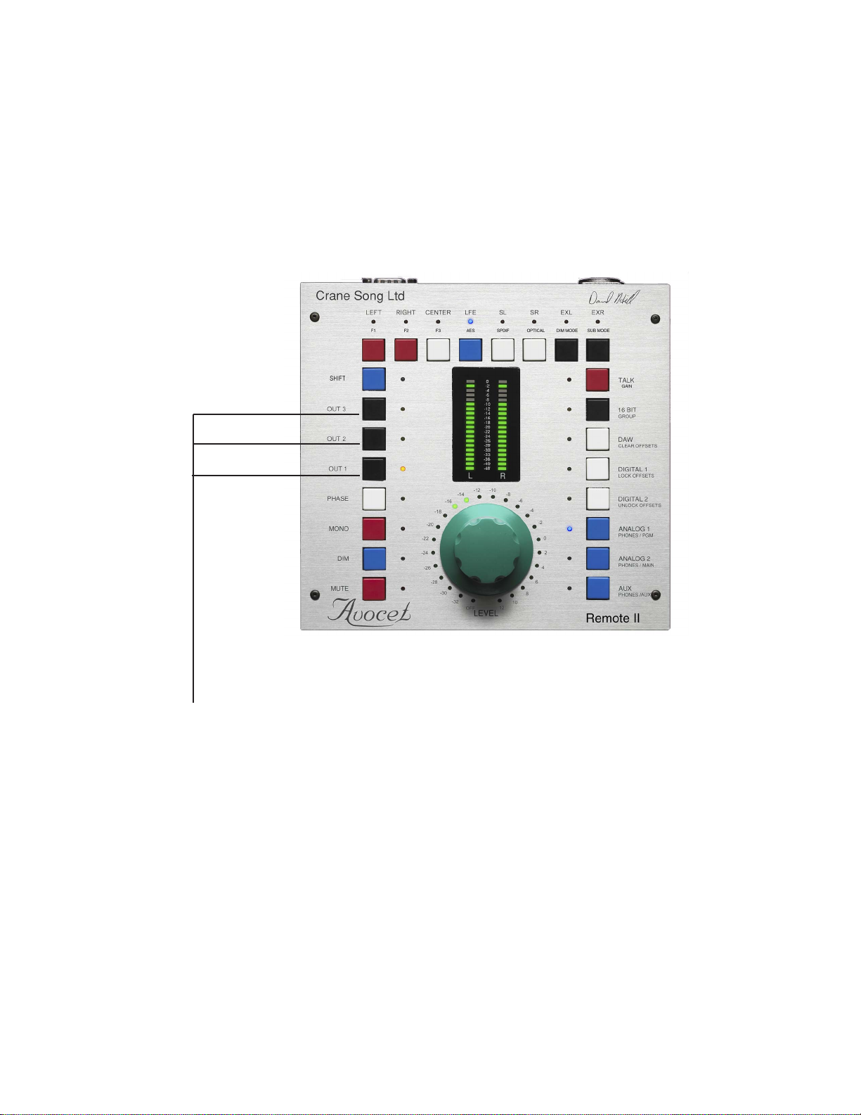
Gain Trims are adjustable
by plus or minus 10db
on all INPUTS and the
MONO function in surround
GAIN TRIMS
6
If one presses and holds the input select button a second time it will enable the input
gain trim mode. It requires about one half second of hold time to enter the trim mode.
Trim mode allows changing the input level on the selected input relative to all other
inputs. Gain trim has an offset range of plus or minus 10 db in 1 db steps. It is adjusted
by turning the GAIN knob. By pressing the input button a third time, the input will return
to normal operation while remembering the gain trim. Selecting any other input will also
exit the trim adjust mode.
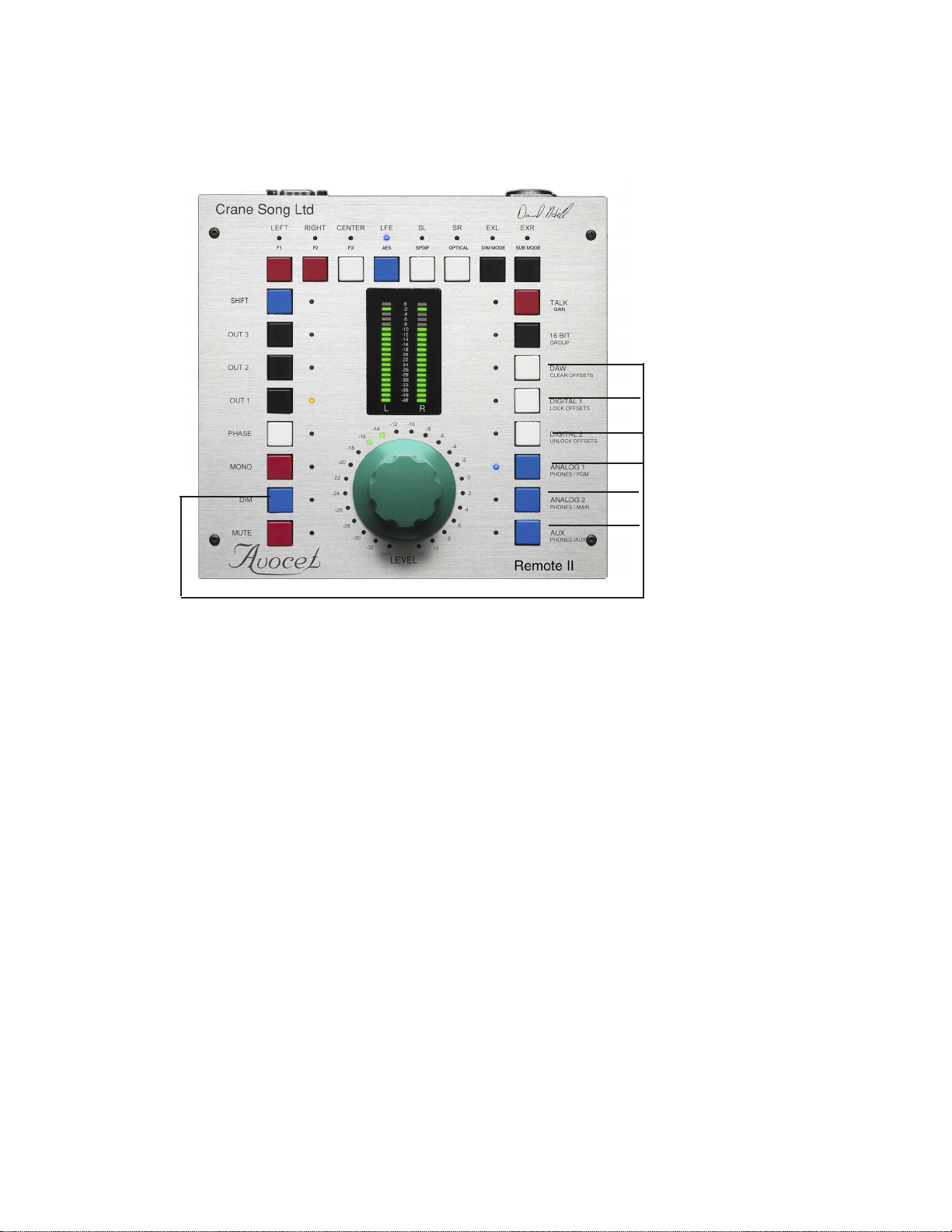
Gain trim can be cleared, locked or enabled by using the Shift key to reach the desired
selection. See shift mode setup functions
The mono function also has a gain trim for level matching in surround. After selecting
mono a second time, if one presses and holds the mono select button for one half
second or more Avocet will enter the mono gain trim mode. To leave the gain trim mode
press the button again. This will cause the gain trim to be remembered and the mono
mode to be exit.
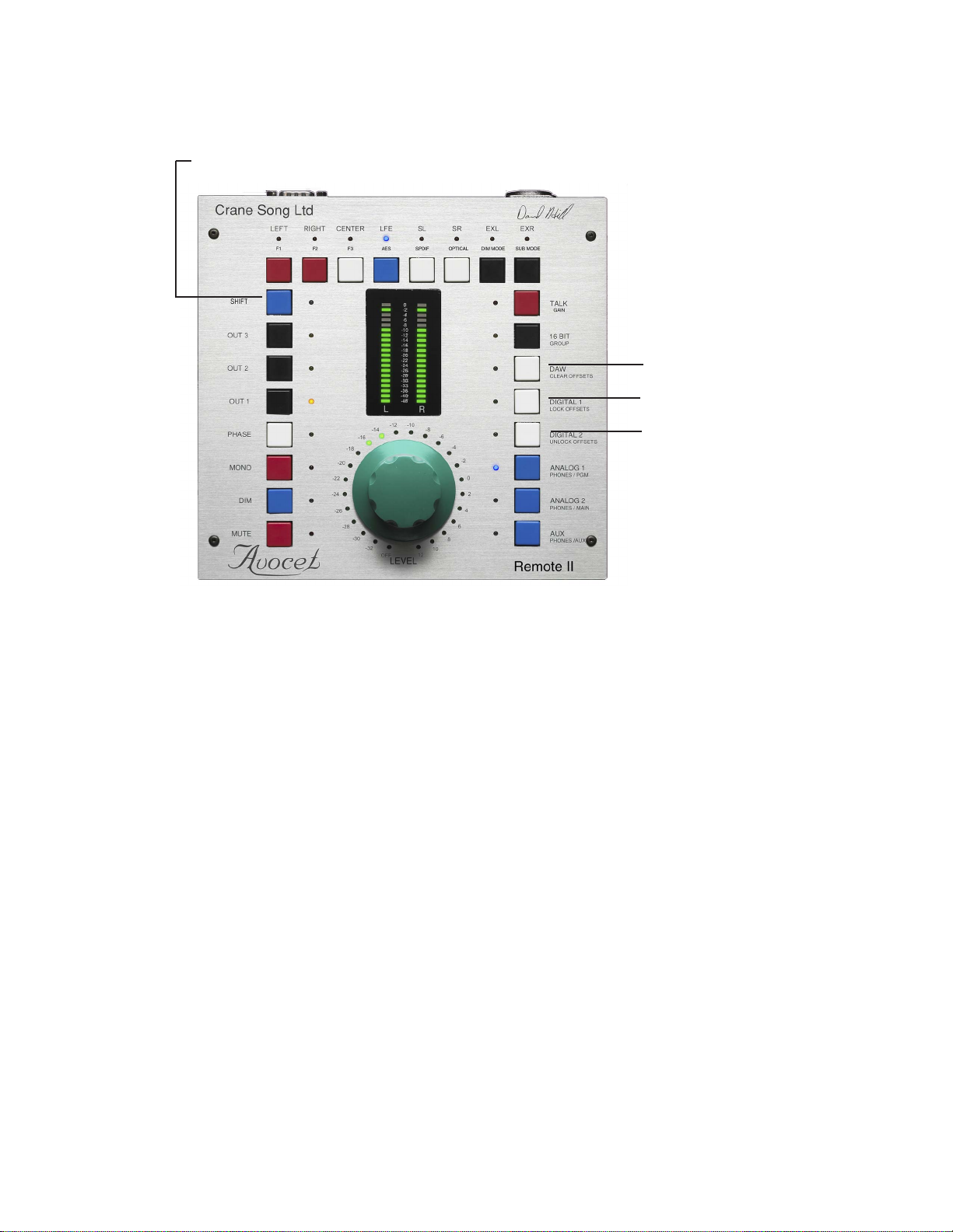
In normal operation all input gains will track. At the end of the stepped attenuator range
the offset gains could reach a limit where they will not change. As an example if you
trim an input up by 10 db and then move the main gain to max that input will be max
+10 which is not possible. Bringing the main gain back down, the 10db offset will still
exist. The same thing will happen on the bottom end of the control range.