5
2) Impeller and Volute Service:
2.1) Disassembly and Inspection:
To clean out volute, disconnect power, remove hex nuts,
lockwashers and socket head cap screws, vertically lift motor
and seal assembly from body. Clean out body if necessary.
Clean and examine impeller for pitting or wear, replace if
required. Inspect Square Ring and replace if cut or damaged.
If impeller requires replacing, remove cap screw and washer.
The impeller is keyed onto the shaft with a square key and
to remove, pull impeller straight off the shaft using a wheel
puller, if required. Before reinstalling, check the motor shaft and
impeller bore for damage.
2.2) Reassembly:
To install impeller, apply a thin film of oil to motor shaft and slide
impeller straight onto shaft, keeping keyways lined up. Drive
key into keyway. Locate washer, apply Loctite to shaft threads,
thread hex nut to shaft and torque to 40 ft. lbs. Rotate impeller
to check for binding.
Position square ring on volute flange and install impeller and
motor housing over studs and onto volute. Apply thread locking
compound to threads of each stud and socket head cap screw.
Thread nut onto stud and thread socket head cap screw into
volute, torque to 30 ft. lbs. Check for free rotation of motor and
impeller.
3) Motor and Bearing Service:
3.1) Disassembly and Inspection:
To examine or replace the motor and bearing, disassemble
pump, volute and impeller (as outlined in paragraph 2.1) and
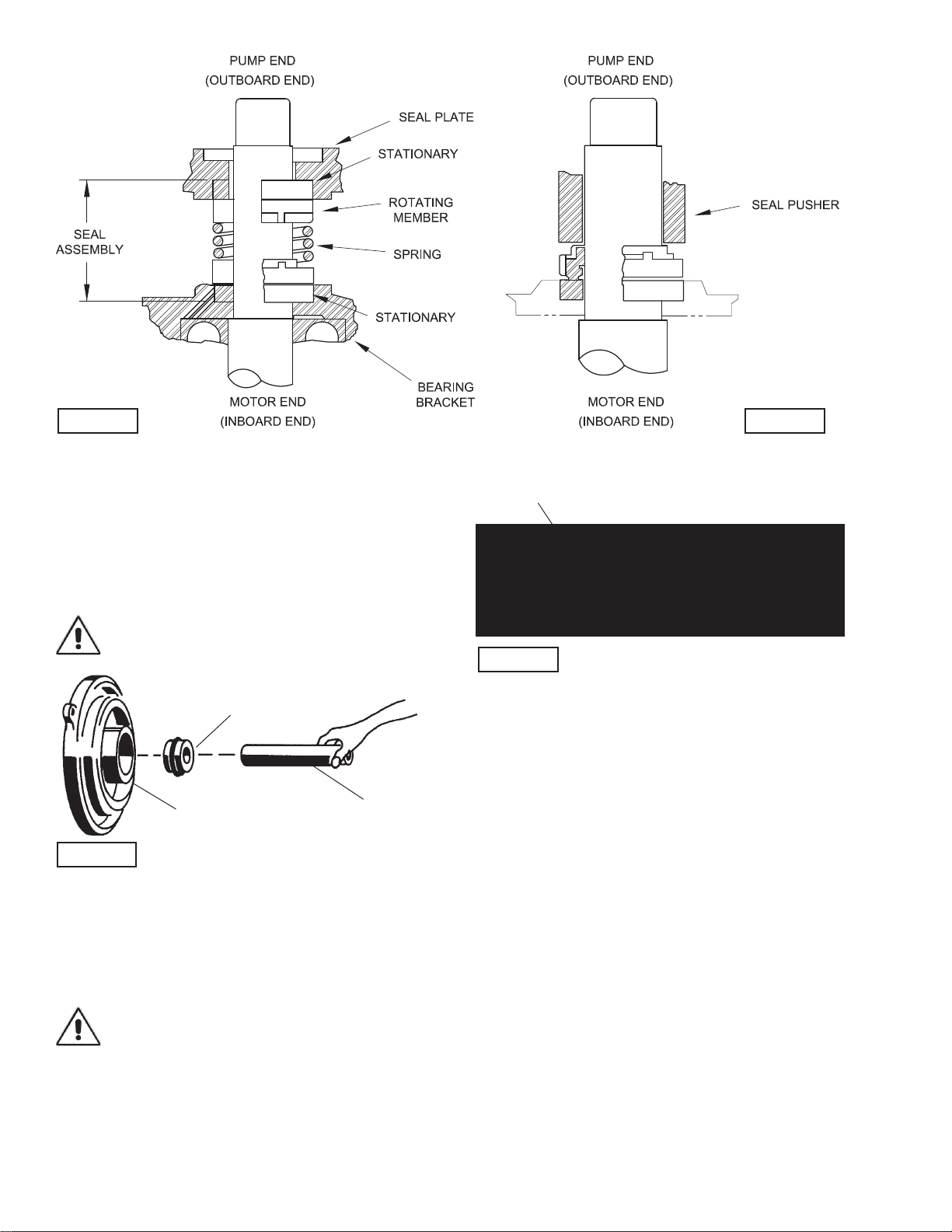
disassemble seal plate and shaft seal (as outlined in paragraph
4.1). Drain oil from motor as outlined in
paragraph 1.2.
Position unit upright, using blocks to avoid resting unit on shaft.
After removal of cable and box assembly from motor housing,
remove cable lead wires from motor lead wires and moisture
and temperature sensors wires (if equipped) from control cable
by unscrewing connectors. The wiring connections should
be noted to insure correct connections when reassembling.
Vertically lift the outside motor housing from bearing bracket
with lifting strap. Inspect square ring for damage or cuts.
Remove the upper motor bolts and lift upper end bell from
motor.
Vertically lift stator. Inspect winding for shorts and resistance.
To test the temperature sensor (if equipped), check for
continuity between the black and white wires. If found to be
defective contact a motor service station or Barnes Pumps
service department. Remove retaining ring from bearing
bracket and pull motor rotor and lower bearing vertically from
bearing bracket. Examine bearing and replace if required. If
replacement is required, remove retaining ring from motor
shaft and remove bearing from motor shaft using a wheel
puller. Check rotor for wear. If rotor or the stator windings are
defective, the complete motor must be replaced. Check motor
capacitor on single phase units and replace if defective. While
disassembled, check moisture sensor wires (if equipped), that
they are secured to electrodes with screws.
Important ! - ALL parts must be clean before
reassembly.
3.2) Reassembly:
Bearing - When replacing bearing, be careful not to damage
the rotor or shaft threads. Clean the shaft thoroughly. Insert
retaining ring onto motor shaft. Apply adhesive compound to the
shaft and press bearing on the motor shaft, position squarely
onto the shaft applying force to the inner race of the bearing
only, until bearing seats against retaining ring.
Motor - Slide lower bearing and motor rotor squarely into
the bearing bracket until bearing seats on the bottom. Insert
retaining ring into bearing bracket.
Position motor housing and stator into pilot, aligning holes
in bearing bracket. Apply thread locking compound on motor
bolts and tighten. Torque motor bolts to 22 in-lbs. Place all
motor leads above the motor. Position square ring on bearing
bracket and lower housing over motor and into pilot. Make wire
connections per paragraph 3.3.
3.3) Wiring Connections:
Check power cable and sensor cord for cracks or damage and
replace if required.
Conduit Box Design:
Bring motor wires through wire opening in top of motor housing,
position square ring in conduit housing and reconnect motor
leads to power cord and moisture and temperature sensor
leads to sensor cord (if equipped) using connectors as shown in
Figure 3.
Terminal Block Design:
Make internal wiring connections which are independent of the
terminal block as shown in Figure 3 using connectors and wire
assemblies as required. Do not use wire nuts. Slip motor leads
and ground wire into fiberglass sleeve. Lower motor housing
down onto bearing bracket while aligning holes and stringing
motor leads through the cord entry bore(s). (Slipping cords
inside a 1 ft. length of .5” conduit makes this easier). Place
socket head cap screws through seal plate into motor housing
and torque to 75 in-lbs. Install inner seal assembly as outlined
in paragraph 4.2. Install square ring, bearing bracket and
square ring in position on pump. Place socket head cap screws
through seal plate and torque to 75 in-lbs.
Reconnect motor and sensor leads to the underside of the
terminal blocks, as shown in Figure 2. Note that the pins are
numbered underneath the terminal block. Place o-ring into
groove in terminal block and lubricate with dielectric oil. Press
the terminal block into the housing so it seats completely below
the retaining ring groove. Place retaining ring into groove in
cord entry bore of housing. repeat terminal block installation for
control cord, if equipped.
FIGURE 2