Crawford Performance Overland Series User manual
Crawford Performance
Pg. 1
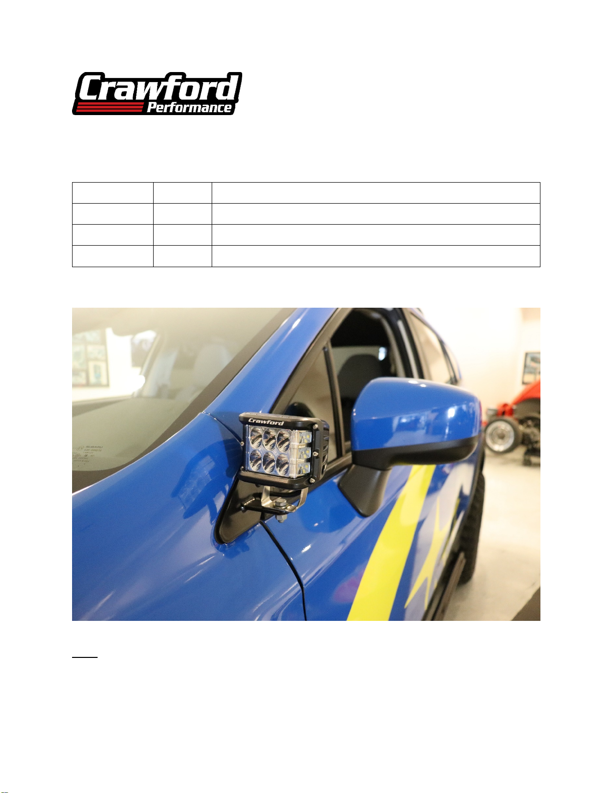
Crawford Performance Overland Series
Mirror Light Pod Kit
2018+ Crosstrek
L0001 Parts List
Part Number
Quantity
Description
W2201-1
1
Wire – Crosstrek Mirror Harness
L2260
1
Light – Directional 90 Degree Sidewinder LED
B2260-1
1
Bracket – 18+ Crosstrek Mirror Light Pod Bracket
Note: This installation will be completed in steps, starting with the wiring harness, and
finishing with mounting the light pod. The order in which these steps are done is not
important, but we have found the method demonstrated in this guide to be the best way to
install the kit.

Crawford Performance
Pg. 2
Hardware:
Tools Needed:
10 MM Socket 8 MM Allen Wrench 3/8” Ratchet 10 MM Ratchet Wrench Flathead Screwdriver
Estimated Install Time: 2 Hours
Install difficulty: 6/10
Other Tools Needed:
-Power Drill
-Drill Bit


Crawford Performance
Pg. 4
3. Slide the bottom end of the provided relay mounting plate over the battery brace strut. Thread the
supplied nut onto the strut about 2 inches down the strut body. This nut will be used to support the
relay plate and prevent it from sliding. Slide the strut through the top of the relay plate and pinch it
in place with another provided nut.
4. Attach the mirror light pod relay to the relay plate. (position on the plate does not matter)

Crawford Performance
Pg. 5
5. Secure the battery strut and relay plate by re-inserting the strut back to its OEM position and
securing with the OEM nut removed in step 2. (10 MM Socket)
6. Remove the plastic trim piece above the driver side fender by releasing the two plastic clips with a
flathead screwdriver as shown. (Flathead Screwdriver)

Crawford Performance
Pg. 6
7. Place a provided sticky harness on the fender rail directly right of the battery as well as across the
top of the engine bay as shown
8. Use a provided wire tie to secure the wire leads to the sticky harness on the fender.

Crawford Performance
Pg. 7
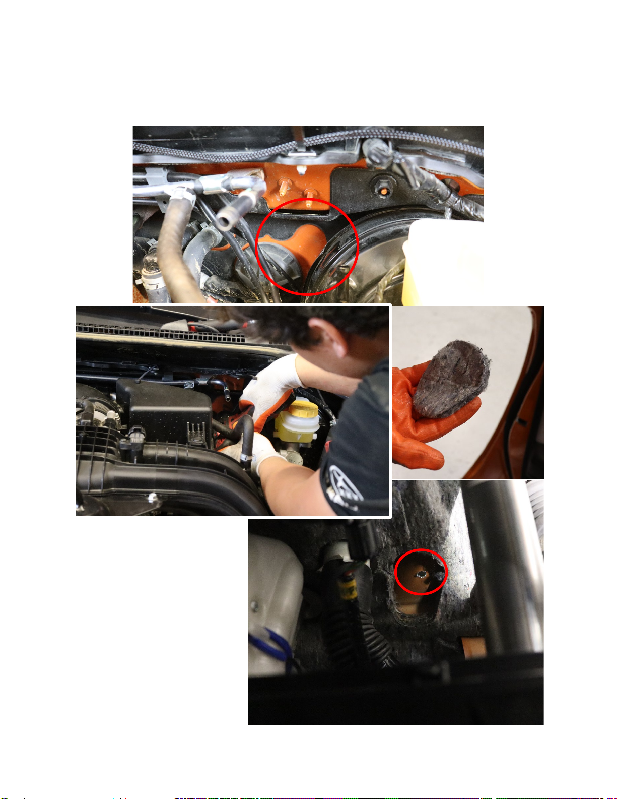
9. Route the wires towards the top of the driver side of the engine bay and set to side.
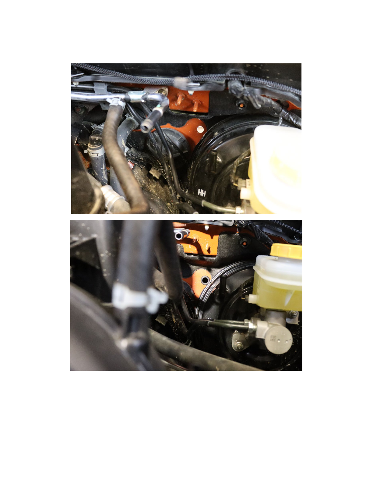
10. Remove the vacuum line leading to the master brake cylinder. (Needle Nose Pliers)
Crawford Performance
Pg. 8
11. Drill a hole through the firewall in the area indicated below using a 5/8” Drill Bit.
Note: The hole location on the interior of the car will be behind a small foam insert that you can
remove from underneath the dash behind the steering column on the left-hand side.
Crawford Performance
Pg. 9
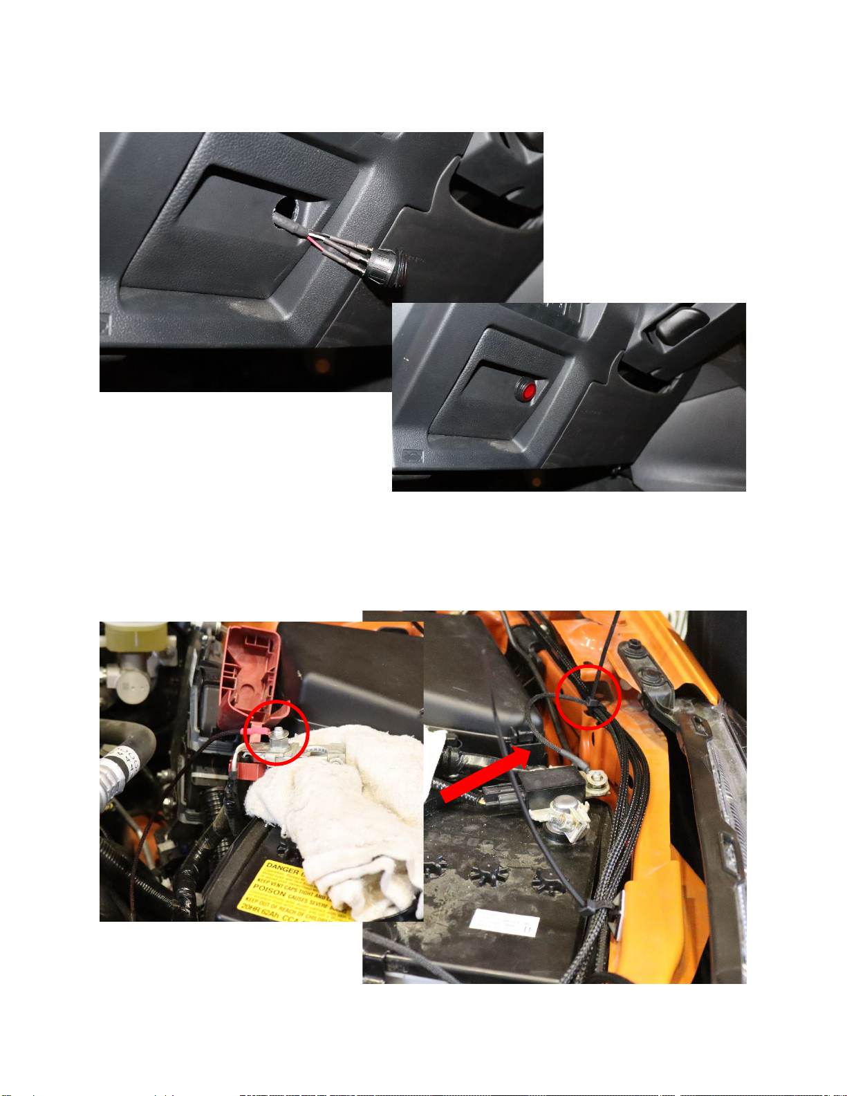
12. Clean out the hole to prepare it to receive the rubber grommet. Once clear of debris, insert the
provided grommet
13. Remove the wire ends connecting the provided switch to the wiring harness, taking note of how the
leads are connected to the switch. (Black to Gold/Top relay, White to middle relay, Red to bottom
relay)

Crawford Performance
Pg. 10
14. Feed the switch wire lead through the hole and into the vehicle cabin so that the wire ends are in
front of the fuse board.
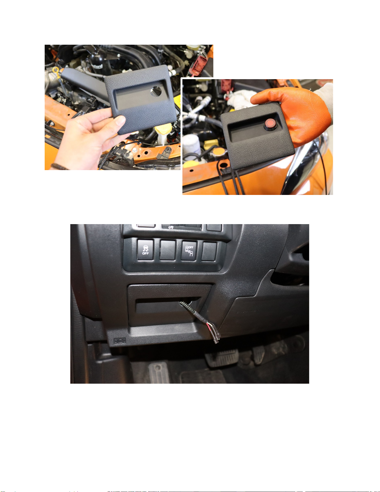
15. Remove the fuse board cover and drill a hole for the switch to be set into.
Crawford Performance
Pg. 11
16. Remove the switch from the fuse board cover panel and reinstall the panel into the car. Feed wires
from firewall through the panel hole you just drilled out.
Crawford Performance
Pg. 12
17. Install the wire ends to the switch and re-insert the switch into the fuse board cover.
18. Returning to the engine bay, fasten the positive and negative eyelets leading from the wiring
harness to the battery as shown. For the negative terminal, zip tie the wires leading to the top of
the engine bay along the fender structure together. Tie of in a spot where the negative eyelet can
still split off and attach to the battery.
Crawford Performance
Pg. 13
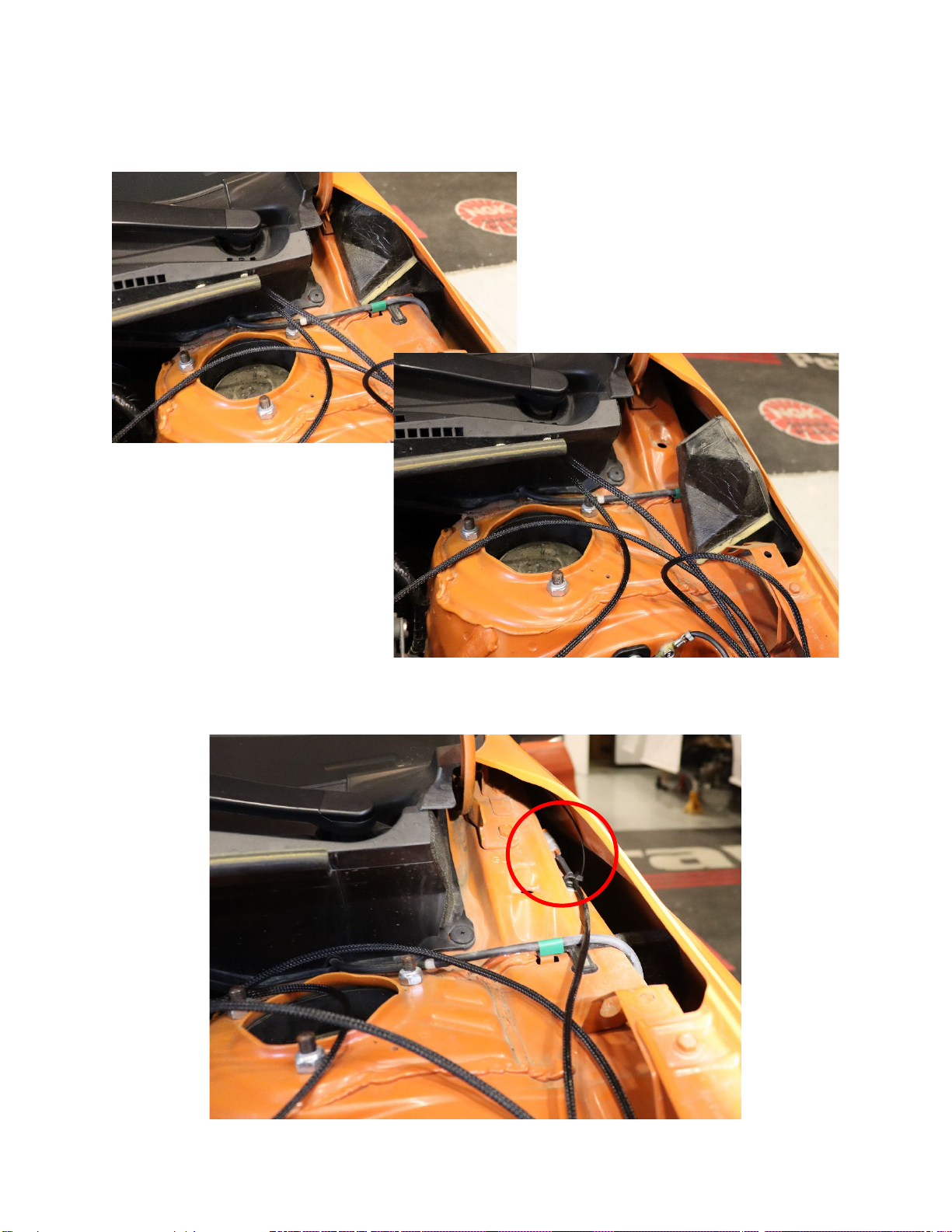
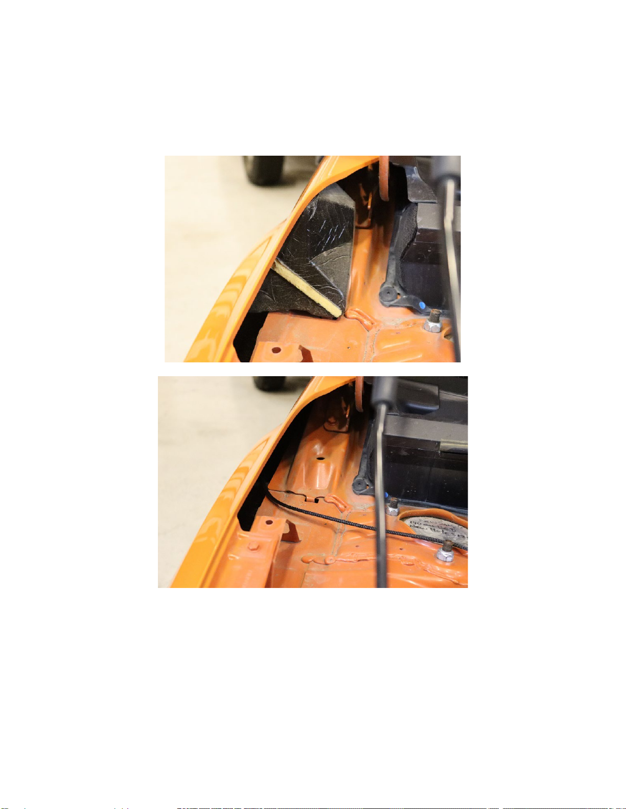
19. Remove the foam insert located in the driver side gap between the fender and the frame of the
vehicle.
20. Place a sticky harness in this gap and zip tie the short pod connector to the harness

Crawford Performance
Pg. 14
21. Run the long wiring connector for the driver side mirror pod across the top of the engine bay where
the sticky harnesses were placed in step 7. Make sure to leave enough slack across the engine
bay for when the wires are tightened down to the sticky harnesses.
22. Use Zip Ties to bundle the wires leading up from the battery and relay plate together. This will keep
the set up clean and ensure the wires run smoothly under the plastic fender trim removed in step 6.
Make sure to leave enough slack for the wire running across the engine bay to the
passenger hood bracket.

Crawford Performance
Pg. 15
23. Take the switch wire that is running through the firewall and route it so it passes through the first
sticky harness on the driver’s side. This wire will only be attached at this sticky harness. The
passenger side pod wire will run through this harness and the remaining harnesses placed down in
step 7. Do not tighten any zip ties at this point.
24. Remove the passenger side fender trim piece by releasing the clips shown below.
Crawford Performance
Pg. 16
25. Remove the foam insert located in the passenger side gap between the fender and the frame of the
vehicle. Route the longer light pod connecting wire across the engine bay and insert the pod wire
into the gap. Let it hang freely so there is play when fastening the wire to the harnesses installed in
step 7.
26. Let the wire ends hang while you begin to prep the mirror brackets and the light pod wires.
Crawford Performance
Pg. 17
Light Pod Preparation Instructions
1. If you have purchased the mirror light pod kit with included light pods, skip to step ___. If you have
your own light pods or bought the CDR series pods separately but have the CDR series wiring
harness, follow the instructions from step one. Specialty electrical tools will be required.
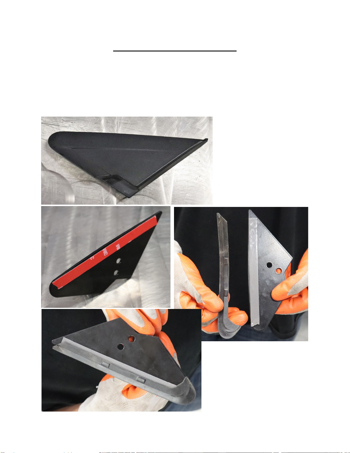
2. Prepare both brackets for mounting by installing the factory weather-strips from the plastic covers
removed in step 1 to the Crawford mirror pod bracket. Use the provided double sided tape to re-
install the rubber weather-stripping.

Crawford Performance
Pg. 18
3. Locate the Deutsch connector wire ends and crimp them to the raw light pod wire ends. Slide the
wire through the mirror pod bracket.

Crawford Performance
Pg. 19
NOTE: Once the wire ends are crimped with the
connectors, slide the wire through the lower hole on
both of the CDR Series Mirror brackets. This is done
so you can mount the pods with the wire in the
proper position. The final results are shown below
for reference.

Crawford Performance
Pg. 20
4. Slide the provided heat shield sleeve over the wire ends. This is simply to prep for later, do not
apply heat yet.
5. Remove the Deutsch connector dust plug from the male connector.
Other manuals for Overland Series
1
This manual suits for next models
1
Other Crawford Performance Automobile Accessories manuals


