Rosco SAFE -T-SCOPE Instruction Manual

Safe-T-Scope®Backup Camera System STSK7360
SAFE -T-SCOPE®
REARVIEW BACKUP CAMERA SYSTEMS
INSTALLATION /USER'S MANUAL
STSK7360

Safe-T-Scope®Backup Camera System STSK7360
STSK7360 SAFE-T-SCOPE®7" COLOR BACKUP CAMERA SYSTEM
Rosco Vision Systems introduces a revolutionary new backup camera system for
commercial vehicles. The STSK7360 Safe-T-Scope®backup camera system utilizes
a 7'' inch monitor to display a 16:9 LCD screen when the vehicle shifts into reverse.
This monitor allows the driver to see obstructions behind the vehicle for added
convenience and safety.
The camera has an advanced CCD image sensor able to process excellent views
under dark and light conditions. A 120° diagonal field of vision yields superb
coverage behind the vehicle, and complies with the latest U.S. DOT guidelines when
installed properly.
Safeguard Instructions . . . . . . . . . . . . . . . . . . . . . . . . . . . . . . . . . . . . . . . . . . . . . 2
Features & Contents. . . . . . . . . . . . . . . . . . . . . . . . . . . . . . . . . . . . . . . . . . . . . . . 4
Installation Instructions . . . . . . . . . . . . . . . . . . . . . . . . . . . . . . . . . . . . . . . . . . . . . 6
Wiring Camera & Monitor . . . . . . . . . . . . . . . . . . . . . . . . . . . . . . . . . . . . . . . . . . 7
Functions & Operations . . . . . . . . . . . . . . . . . . . . . . . . . . . . . . . . . . . . . . . . . . . . 8
Setting . . . . . . . . . . . . . . . . . . . . . . . . . . . . . . . . . . . . . . . . . . . . . . . . . . . . . . . 16
Installation of U-Bracket . . . . . . . . . . . . . . . . . . . . . . . . . . . . . . . . . . . . . . . . . . . 18
Installation of Duckfoot Mount. . . . . . . . . . . . . . . . . . . . . . . . . . . . . . . . . . . . . 19
Connection. . . . . . . . . . . . . . . . . . . . . . . . . . . . . . . . . . . . . . . . . . . . . . . . . . . . . . 20
Figure Drawings . . . . . . . . . . . . . . . . . . . . . . . . . . . . . . . . . . . . . . . . . . . . . . . . . 21
Specifications . . . . . . . . . . . . . . . . . . . . . . . . . . . . . . . . . . . . . . . . . . . . . . . . . . . 26
TABLE OF CONTENTS
1
7” Waterproof Monitor
Please read the “Safety Rules“ carefully before using this product.
Following the safety rules prevents users from damage related with the misuse
of the product. It is very important to follow these safety rules.
We state “Caution“ and “Warning“ to clarify any potential risk for a damage
associated with the misuse of the product.
This information is for the user’s reference for better usability.
This information is for preventing damage.
This information is for preventing bodily harm. User should follow safety rules.
CAUTION
• Install all components while power is off.
- FAILING TO DO SO MAY CAUSE ELECTRONIC SHOCK OR MALFUNCTION.
•Do not connect the product directly to the battery, use switched ignition.
- DOING SO MAY DRAIN THE BATTERY
• Do not use this product with multi socket or extended adaptor.
- DOING SO MAY CAUSE UNEXPECTED HEATING, FIRE AND MALFUNCTION.
• When product is not in use for an extended period of time - power off the monitor
- FAILING TO DO SO MAY CAUSE FIRE BY SHORT CIRCUIT DUE TO HEATING.
• Do not place near magnetic devices.
- DOING SO MAY CAUSE SCREEN DISTORTION OR PERMANENTLY
DAMAGE THE LCD.
* Please ensure that the monitor is installed with enough room for heat emission.
SAFEGUARD INSTRUCTIONS
i
2

Safe-T-Scope®Backup Camera System STSK7360
3
CAUTION
• Do not install product in direct sunlight, high temperature, or extremely humid areas
- THIS MAY CAUSE ELECTRONIC SHOCK OR MALFUNCTION.
• Please use this product within the voltage range specified
- THIS MAY CAUSE ELECTRONIC SHOCK OR MALFUNCTION.
• Do not place this product where air bag operation may occur
- THIS MAY CAUSE MALFUNCTION OF AIR BAG OR INJURY DUE FROM BAG
HITTING MONITOR.
• Do not place this product in high vibration areas without appropriate mounting
- THIS MAY CAUSE DAMAGE OR MALFUNCTION
• Do not drill or screw directly into body
- THIS MAY CAUSE ELECTRONIC SHOCK, FIRE AND MALFUNCTION
• If the monitor is emitting smoke or a burning smell disconnect immediately
- THIS MAY CAUSE FIRE
• Do not disassemble, repair or remodel
- THIS MAY CAUSE MALFUNCTION AND INJURY, VOID WARRANTY
• Do not disassemble, repair or remodel
- THIS MAY CAUSE MALFUNCTION AND INJURY, VOID WARRANTY.
• When the power cable cord touches a metal case, cover it with a friction tape.
- SHORT CIRCUIT OR DISCONNECTION OF WIRE MAY CAUSE A FIRE.
* After finishing the installation, please check that the brake lamp, head lamp, and
wipers operate properly.
SAFEGUARD INSTRUCTIONS
4
FEATURES &CONTENTS
FEATURES - 7” WATERPROOF MONITOR
• Dimmer sensor built in
• 7” WVGA (800 x 480) Wide LCD Panel
CONTENTS -7”WATERPROOF MONITOR
•Before using this product, please check contents below. If there are
any missing parts please contact a Rosco sales agent or dealer.
Monitor
Monitor Power
Harness
Power Adaptor
Cable
Trigger Extension
Cable (x4)
Instruction
Manual U-Bracket Sun Visor
(Optional) Duckfoot Mount
1
2
3
46
7
810
9
11
5
STSM207 MONITOR SPECIFICATIONS
* Design and
specification are
subject to change
without notice.
1. Automatic brightness
control sensor
2. Dimmer
3. Mode
4. Up
5. Down
6. Left
7. Right
8. Menu
9. Power
10. Stand by lamp
11. Speaker
(Waterproof)
CONTROLS
7”
4 Inputs/Channels
16:9
Quad (4)
300:1
NTSC
12~24 Vdc
-22° to 158° (-30° to +70°)
-40° to 176° (-40° to +80°)
IP67
100g
15g
8 Ohms
1.5 lbs.
7” x 5.30” x 1”
Included
400 cd/m2
Versatile Duckfoot & U-Bracket
Screen Size (Diagonal)
Maximum No. of Cameras
Screen Ratio
Split Screen Function
Contrast Ratio
Video System
Voltage Input
Operating Temperature °F (C°)
Storage Temperature °F (C°)
Dust\Water Rating
Shock Rating
Vibration Rating
Speaker Impedance
Weight
Dimensions W x H x D
Sun Shade
Brightness
Monitor Mounting Options

Safe-T-Scope®Backup Camera System STSK7360
5
FEATURES AND CONTENTS
Image Device
Pixels
TV Lines
InfraRed LED’s
Night Vision Range
Video Output
Dust\Water Rating
Shock Rating
Vibration Rating
Field of View
Operating Temperature °F (°C)
Storage Temperature °F (°C)
Weight
Dimensions W x H x D
Audio
Construction
1/3” CCD
250,000
380
6 High-Output
30 Feet
1.0 Vp-p, 75 Ohm
IP67
100G
15G
145°
-22° to 158° (-30° to +70°)
-40° to 176° (-40° to +80°)
.5 lb.
2.5” x 1.7” x 2.5”
Yes
Cast Aluminum Housing w/ Stainless Steel
Mounting Bracket & Weather Shield
STS107 CAMERA SPECIFICATIONS
INCLUDES STSH307 (60’ HARNESS)
See fig. 3 ( pg.25)
IMPORTANT: FOR TYPICAL REAR-VIEW INSTALLATION, THE REAR CAMERA MUST
BE CONNECTED TO THE MONITOR POWER DISTRIBUTION HARNESS AT THE
CONNECTOR MARKED “REVERSE”
Note: The following instructions are for a typical rear-view application.
STSC107 CAMERA
1. Attach camera bracket close to rear marker lights, centered on vehicle (see Fig. 1).
Attachment point must be sturdy enough to support camera and bracket.
2. We do not recommend mounting the camera near the lower area of the
vehicle (ex: bumper). This reduces the view of the camera and increases
the chance of physical damage to the camera.
3. Attach camera to bracket using screws provided. Adjust angle as indicated
in Fig. 2. (Use rear bumper and back of vehicle as a reference point.)
4. Wind deflector may be installed. This deflector is designed to reduce the
buildup of dust, dirt and moisture on the camera lens. (See Fig.3)
STSM207 MONITOR
1. Attach monitor inside vehicle in a location convenient to the driver
(ex: center of dash, overhead, or flush-mounted in dash).
2. Attach the “duckfoot“ bracket to the dashboard or to the headliner
using self-tapping screws and/or adhesive pad.
3. Fasten monitor to “duckfoot“ and adjust mounting angle to allow optimum driver
viewing comfort. (See Fig. 4.)
CAMERA
1. The camera to cable connection is waterproof. Be sure to position the cable
properly. The male end attaches to the camera. The female end attaches to the
power/video/audio distribution harness, typically located under the dashboard.
(See Fig. 5.)
IMPORTANT: FOR TYPICAL REAR-VIEW INSTALLATION, THE REAR CAMERA MUST
BE CONNECTED TO THE DISTRIBUTION HARNESS AT THE CONNECTOR
MARKED “REVERSE”
2. Do not run the cable over sharp edges or corners. Do not kink or excessively bend
the cable.
Keep the cable away from hot and rotating parts.
3. Fasten all cable runs, and secure all excess cable.
INSTALLATION INSTRUCTIONS
6

Safe-T-Scope®Backup Camera System STSK7360
1. Connect the red wire to an ignition switched accessory (ex: radio) power source,
and connect the black wire to chassis ground. See wiring diagram for connections
(See Fig. 5.)
2. Before drilling, be sure no cable or wire is on the other side. Be sure to drill
a 20mm (0.8in) diameter hole only.
3. Feed as much cable as possible into vehicle and clamp securely. This
reduces the possibility of it being hooked or snagged.
4. Keep all cables away from HOT, ROTATING and ELECTRICALLY NOISY
components.
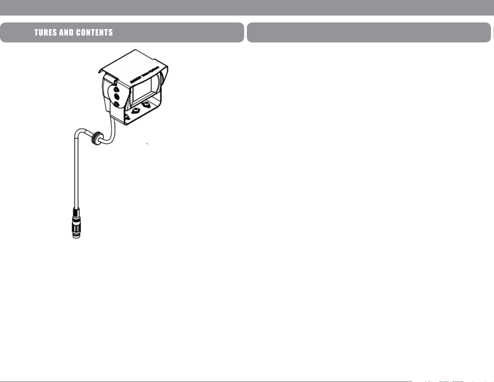
5. Camera: Drill a 20mm (0.8in) diameter hole into vehicle body near the camera and
bracket. Insert camera cable into vehicle (be careful not to kink cable) and fit
grommet into hole. Apply sealant around grommet to increase resistance to water
penetration. Connect camera to the camera extension cable which runs inside
the vehicle.
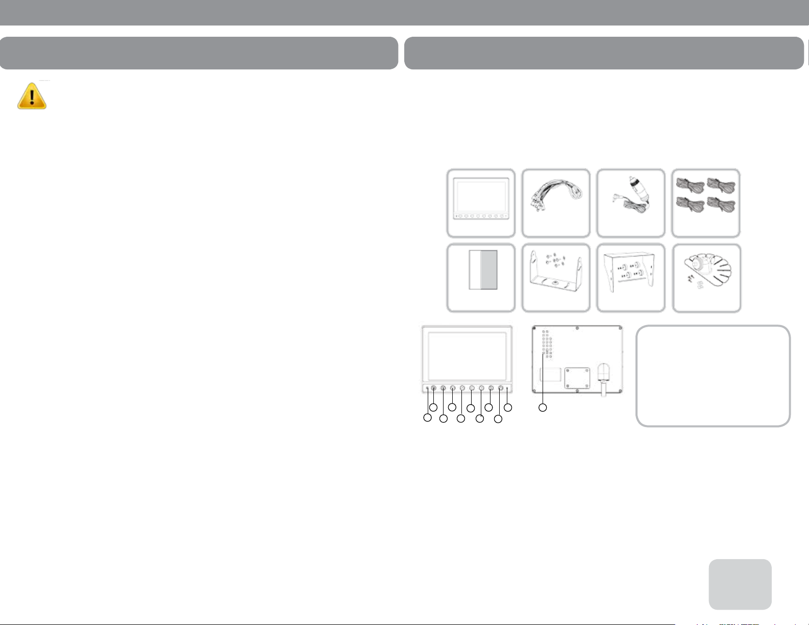
6. Monitor: The monitor terminates in a 13-pin connector, which should be connected
to the mating 13-pin receptacle end of the power/video/audio distribution harness.
7. For typical rear-view installation, connect the camera extension cable
from the rear-view camera to the harness’s connector marked REVERSE.
8. For multi-camera installations, be sure to mark each extension cable properly and
connect to the appropriate harness connector marked CA1 or CA2. Bundle excess
cable together using a cable tie or electrical tape.
9. The green wire is the REVERSE trigger wire. In typical rear-view installations,
connecting this wire to the vehicle’s backup light circuit will activate the rear-view
image whenever the vehicle shifts into reverse.
10. FUEL TANKERS & OTHER SPECIALTY VEHICLES: All electrical equipment
fitted to petroleum vehicles must be connected via battery master switch and must
be isolated from the battery while the vehicle are loading and unloading. For other
specialty vehicles, please check applicable code and regulations prior
to installation.
11. Always consult your dealer when fitting any electrical or electronic equipment to a
vehicle fitted with a CAN-bus or multiplex system.
IMPORTANT: FOR INSTALLATIONS REQUIRING MULTIPLE CAMERAS, OR FOR
INSTALLATIONS NOT REQUIRING TYPICAL REAR-VIEW IMAGES, PLEASE REFER
TO THE WIRING DIAGRAM (FIG.5) AND THE PARTICULAR VEHICLE’S
ELECTRICAL SCHEMATIC FOR SELECTION OF PROPER POWER AND TRIGGER
CONNECTION POINTS.
WIRING CAMERA AND MONITOR
7
MONITOR FUNCTIONS AND OPERATIONS
MONITOR
1. POWER
When the ignition is switched on, the monitor will be in standby mode (no image
will be on the screen), waiting for trigger signal.
When a trigger wire is energized by 12v power (such as backup lights turning on),
the image captured by the selected camera will appear on the monitor.
2. Pressing the power switch will change the monitor status from standby to
steady-on. Steady-on mode status will show rear cameras view.
3. VOLUME +/-
Adjust Speaker Volume
These buttons are also used to adjust the values within selected setting of menu option
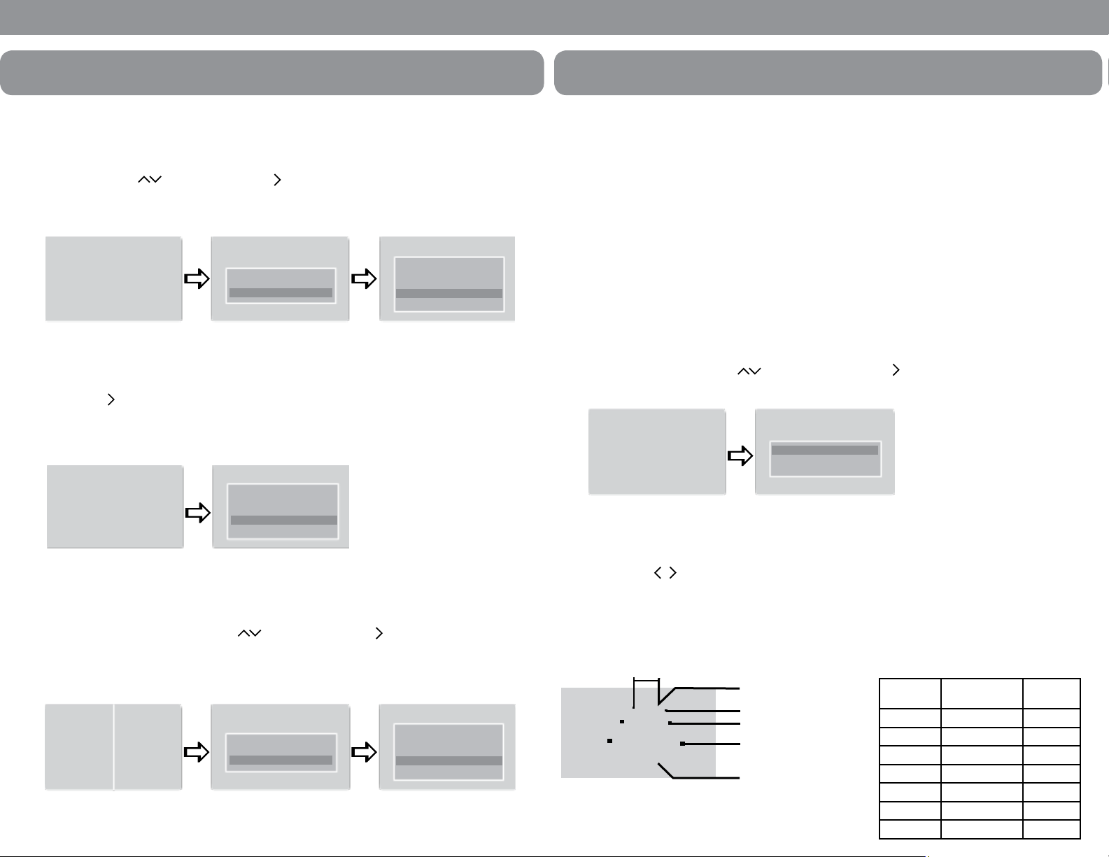
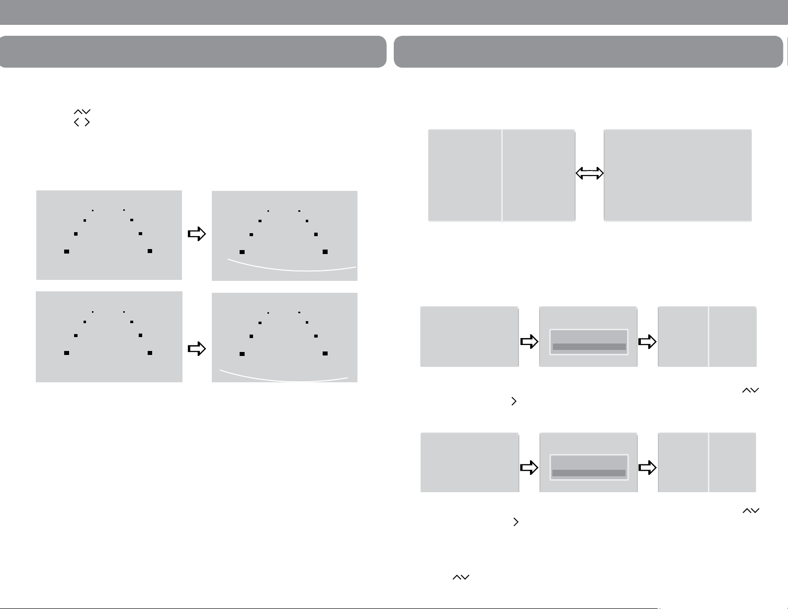
4. MODE
Switching the screen mode.
Press MODE once
Full screen changes to 2 split screen.
Press Mode twice
2 slpit screen changes to 3 split screen.
Press Mode three times
3 split screen changes to 4 split screen.
Press Mode four times
4 split screen changes back to full screen.
SPLIT SCREEN & CAMERA FUNCTION
1. SPLIT SCREEN SWITCH
In the split screen, press button to view the alternate split screen views
half view
1
tri view
1
quad view
1
quad view
2
tri view
2
half view
2
8

Safe-T-Scope®Backup Camera System STSK7360
2. CAMERA SELECTION
From the FULL SCREEN in the full screen, press the button to see
CAM1 > CAM2 > CAM3 > CAM4 > CAM1 . . . .
Press the “Mode“ buttton to display the screen information (Input Mode/Volume)
3. CAMERA SELECTION FOR SPLIT SCREENS
In the 2 split screen press the “Mode“ button to see the OSD(On Screen Display).
While the OSD is on select with the button the camera position
(Left or Right). Then press the arrow to select the camera of choice.
FUNCTIONS AND OPERATIONS
CAM1
CAM4 CAM4
CAM2
SPLIT SCREEN SETUP
SET LEFT
SET RIGHT
SPLIT SCREEN SETUP
CAM 1
CAM 2
CAM 3
CAM 4
CAM2
9
FUNCTIONS AND OPERATIONS
4. CAMERA SELECTION FOR 3 SPLIT SCREENS
In the 3 split screen press the “Mode“ button to see the OSD (On Screen Display).
While the OSD is on, select with the button the camera position
(Left, Top or Bottom). Then press the button to select the camera of choice.
5. CAMERA SELECTION FOR 4 SPLIT SCREENS
In the 4 split screen press the “Mode“ button to see the OSD (On Screen Display).
While the OSD is on, select with the button the camera position (Top Left,
Top Right. Bottom Left or Bottom Right). Then press the arrow to select the
camera of choice.
NORMAL/MIRROR VIEW
1. CAM1 FULL SCREEN
From the CAM1 full screen press the “Mode” button. From the “MARKER SETUP”
screen press the “Mode” button again. Select the desired camera with the
then press button to change Normal/Mirror view.
SPLIT SCREEN SETUP
SET LEFT
SET TOP
SET BOTTOM
SPLIT SCREEN SETUP
CAM 1
CAM 2
CAM 3
CAM 4
CAM2
SPLIT SCREEN SETUP
SET LEFT
SET TOP
SET BOTTOM
SPLIT SCREEN SETUP
CAM 1
CAM 2
CAM 3
CAM 4
CAM2
MARKER SETUP
ON
OFF
MIRROR SET
CAM1 MIRROR
CAM2 MIRROR
CAM3 NORMAL
CAM4 MIRROR
CAM1
10

Safe-T-Scope®Backup Camera System STSK7360
FUNCTIONS AND OPERATIONS
2. CAM2 OR CAM3 FULL SCREEN
From the CAM2 or CAM3 full screen press the “Mode” button. From the
“CAM2 TRIGGER SETUP” screen press the “Mode” button again. Select the desired
camera with the button then press button to change Normal/Mirror view.
3. CAM4 FULL SCREEN
From the CAM4 full screen press the “Mode” button. Select the desired camera with the
then press button to change Normal/Mirror view.
4. SPLIT SCREENS (2/3/4)
From any multiple screen views press the “Mode” button. From the
“SPLIT SCREEN SETUP“ select a camera press the “Mode“ button again.
Select the desired camera with the button then press button to change
Normal/Mirror view.
CAM4 MIRROR SET
CAM1 MIRROR
CAM2 MIRROR
CAM3 NORMAL
CAM4 MIRROR
CAM2TRIGGER SETUP
FULL SCREEN
SPLIT SCREEN
MIRROR SET
CAM1 MIRROR
CAM2 MIRROR
CAM3 NORMAL
CAM4 MIRROR
CAM2
SPLIT SCREEN SETUP
SET LEFT
SET RIGHT
MIRROR SET
CAM1 MIRROR
CAM2 MIRROR
CAM3 NORMAL
CAM4 MIRROR
CAM1 CAM2
11
FUNCTIONS AND OPERATIONS
Vehicle width (From bumper toward rear)
7M
MARKER
SELECT 5M
P1
3M
1M
Bumper position
CCD camera installation conditions
(distance marker input conditions)
(Unit mm)
Marker No
(Pattern)
Camera Install
Height
Vehicle
Width
P1 2.000 2.500
P2 2.250 2.300
P3 2.500 2.300
P4 2.750 2.300
P5 3.000 2.300
P6 3.250 2.300
P7 3.500 2.500
CAM4
MIRROR SET
ON
OFF
IMPORTANT
• The on screen distance markers should be considered as a general reference to
assist the driver in assessing the distances depicted on the screen. The distance
markers have been designed based on the “CCD camera installation conditions“
listed in the next section, but differences in vehicle design and construction may
result in the actual installation condition or location being different from the
conditions listed. In such cases, the display location should be set at the closest
marker No.
• The markers may not indicate the exact position of the bumper, the vehicle’s
width or the distance to the rear. USE AS REFERENCE ONLY.
12

Safe-T-Scope®Backup Camera System STSK7360
FUNCTIONS AND OPERATIONS
3. MARKER ADJUSTMENT (ADJUSTING THE BUMPER POSITION)
- Press “Mode“ button 5 times, select MARKER ADJUST from the menu.
- Press button, select H/V. (H: horizontal, V: vertical)
- Press button, and switch marker patter.
( H= -10~ +10, V= -12~ +12, Default setting: H=0, V=0)
- After 10 seconds, set up screen disappears, and set up finishes.
* If there is no button operation, set up screen disappears even during set up process
TRIGGER INPUT
1. SCREEN SWITCH WHILE TRIGGER INPUT
What is “Trigger Input“ or “Trigger Signal“? This is when a circuit send s signal to
the monitor showing connected camera on screen during driving mode.
(ex. if driver uses left/right turn signal or reverse gear.)
*Example below is set with TRG1(Rear light) = CAM1
TRG2(Left Signal) = CAM2
TRG3(Right Signal) = CAM3
TRG4(ETC.) = CAM4
13
P1
H 0
V 0
P1
H+10
V 0
P1
H 0
V 0
P1
H 0
V-12
2. If there is trigger input, the connected screen (Trigger input screen) is displayed as
full screen and the screen goes former one when the signal disappear.
3. In case of TRG2 and TRG3 input, by the OSD, the full or split screen could be
selected. If there is the TRG2(3) signal input, then CAM2(CAM3) and CAM1 split
screen are shown on the screen. With this function, Left (Right) and Rear side
could be checked.
In CAM2 full screen, press the “Mode” button to see OSD. Select split screen with
button and then press button. If there is the left signal input (TRG2), then CAM2 (Left)
in left side and CAM1 (Rear) in right side will be shown on the screen.
In CAM3 full screen, press the “Mode” button to see OSD. Select split screen with
button and then press button. If there is the left signal input (TRG3), then CAM1 (Rear)
in left side and CAM3 (Right) in right side will be shown on the screen.
4. When there is the TRG1(Rear light) input, CAM1 video will be shown on the screen.
with button, the 2 split screen CAM2/CAM1 or CAM1/CAM3 could be displayed.
FUNCTIONS AND OPERATIONS
CAM4CAM1 CAM2
CAM2 CAM1
CAM2
CAM2TRIGGER SETUP
FULL SCREEN
SPLIT SCREEN
CAM1 CAM3
CAM3
CAM3TRIGGER SETUP
FULL SCREEN
SPLIT SCREEN
14

Safe-T-Scope®Backup Camera System STSK7360
5. When there is the TRG1(Rear light) input, CAM1 video will be shown on the screen.
with button, the 2 split screen CAM2/CAM1 or CAM1/CAM3 could be displayed.
6. In case of light on emergency blinker (TRG2+TRG3), the monitor display CAM1~
CAM4 as quad split screen. And the screen goes former one when the signal
(light on emergency blinker) is disappeared.
FUNCTIONS AND OPERATIONS
CAM2
Button
Button
CAM1 CAM3
CAM1
CAM1
CAM1CAM1
CAM2
CAM2
CAM3
CAM4
The example is set with TRG1(Rear light)=CAM1 / TRG2(Left signal
light)=CAM2 / TRG3(Right signal light)=CAM3 / TRG4(etc)=CAM4.
i
15
FUNCTIONS AND OPERATIONS
7. When there is input signal more than 2 triggers, the monitor display fully connected
screen (Trigger input screen) as the priority order. And the screen goes former one
when the signal is disappears, the rest will be display as the priority order.
TRIGGER PRIORITY ORDER
TRG1(Rear light) > TRG2+3(Emergency light) >
TRG2(Left side light) > TRG3(Right side light) > TRG4
* If the screen turns by trigger signal, the POWER, MENU & MODE buttons are disabled.
* In the standby position if the trigger wire is activated the monitor will turn on.
The screen will turn off once the power is de-activated to the trigger wire.
The screen will then turn off when the trigger signal has gone off.
CAM3CAM1
CAM4
SETTINGS
VIDEO SYSTEM
1. NTSC/ PAL conversion
Press the “MODE“ button until OSD menu “PICTURE SETUP“ appears.
Press button to select “VIDEO SYSTEM“ and use to enter selection.
If using PAL system on NTSC system using county, it may cause a malfunction. The product
can convert NTSC / PAL system manually but it is not automatic. Before use, Please check
and set the system.
* NTSC system country: USA, CANADA, JAPAN, KOREA, TAIWAN, MEXICO, etc.
PAL system country : AUSTRALIA, GERMANY, U.K., NETHERLANDS, ITALY, etc.
16

Safe-T-Scope®Backup Camera System STSK7360
DIMMER
2. Dimmer sensor setting
Press the “MODE“ button until OSD menu “PICTURE SETUP“ appears.
Press button to select “DIMMER“ and use to enter selection.
Press the “DAY/NIGHT“ button to switch DAY >> NIGHT >> AUTO >> DAY
* Dimmer is set AUTO from the factory
PICTURE
3. PICTURE SETUP
Press the “Mode“ button until OSD menu “PICTURE SETUP“ appears.
Press button to select changes and use to adjust value.
* Each factory setting is preset to 50.
LANGUAGE
4. LANGUAGE DISPLAY SELECTION
Press the “Mode“ button until OSD menu “PICTURE SETUP“ appears
Press button to select changes and use to adjust value.
* Language selection: ENGLISH - FRENCH - GERMAN - ITALIAN - SPANISH
17
SETTINGS
FACTORY SETTINGS
5. Reset
• Press the “MODE“ button until OSD menu “PICTURE SETUP“ appears.
• Press button to select “RESET“ and use to enter selection.
* All settings are initialized at the factory mode except for the video input. (NTSC/PAL)
INSTALLATION OF U-BRACKET
1. Ensure that the monitor is installed with enough room for heat emission. Install the
monitor stand with enclosed screws and double side adhesive tape as shown in the
above image.
2. Fix the monitor to the monitor stand firmly.
3. Sun Visor should be installed with 4 screws.
18

Safe-T-Scope®Backup Camera System STSK7360
INSTALLATION OF DUCKMOUNT
1. Ensure that the monitor is installed with enough room for heat emission. Install the
monitor stand with enclosed screws and double side adhesive tape as shown in the
above image.
2. Fix the monitor to the monitor stand firmly.
3. Sun Visor should be installed with 3 screws.
19
CONNECTION
MINI-DIN A TYPE
20

Safe-T-Scope®Backup Camera System STSK7360
FIG. 1
Camera mount in
suggested location
Mount Camera assembly high.
(centered)
Camera Mounting Hole Pattern
21
Typical monitor image of view from properly installed camera
Street
Vehicles behind truck
Rear Bumper
FIG. 2
Position of camera
22

Safe-T-Scope®Backup Camera System STSK7360
Optional Wind Deflector
FIG. 3
23
Mounting on ceiling
Mounting on the dash, console etc.
FIG. 4
24

Safe-T-Scope®Backup Camera System STSK7360
FIG. 5
Note: For typical single camera installation, this trigger wire should be connected
to the vehicle’s “back up lights” circuit, and the rear-view camera should be
attached to the connector marked “REVERSE”
25
Cam 1 Trigger
Cam 2 Trigger
Cam 3 Trigger
Cam 4 Trigger
Positive 12VDC
* Black wire is the reverse trigger wire, connect to vehicle backup
light circuit. Monitor will turn on when the vehicle shifts into reverse.
15 PIN DIN
CONN (F-M)
STSH307 (65FT’)
(M-F)
(M-F)
STSH347 (32 inches)
STSM207STSC107
26
NOTES

A CENTURY OF AUTOMOTIVE VISION SAFETY
90-21 144th Place, Jamaica, New York 11435
TEL (800) 227-2095 • FAX (718) 297-0323
info@roscomirrors.com
www.roscomirrors.com www.roscovision.com
M080116B
This manual suits for next models
1
Table of contents
Other Rosco Automobile Accessories manuals

Rosco
Rosco STSM240 Assembly instructions

Rosco
Rosco STSK4533 User manual

Rosco
Rosco STSK453X Series Instruction Manual

Rosco
Rosco Mor-Vision STSK1030 Instruction Manual

Rosco
Rosco SAFE -T-SCOPE STSK7165 Instruction Manual

Rosco
Rosco Dual-Vision XC4 User manual

Rosco
Rosco Safe-T-Scope STSK7565 Instruction Manual

Rosco
Rosco DMG DASH User manual

Rosco
Rosco STSK453X Series Instruction Manual

Rosco
Rosco STSW1001 Series Instruction Manual