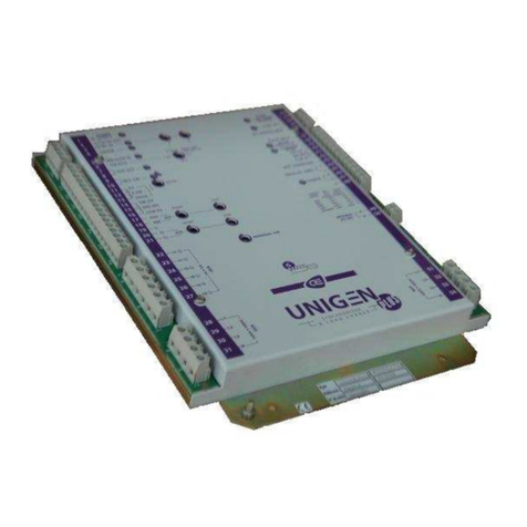
CRE Technology UNIGEN 2.0 synchro User manual

UNIGEN 2.0 synchro
Slave Synchro Unit
USER MANUAL –TECHNICAL DOCUMENTATION
Part Number: A51V0 9 0020 A EN
Last Update: January 2017

User manual –technical documentation A51 V0 9 0020 A EN
2
Technical documentation history
Date
Version
Comment
January, 2017
A
Initial edition

A51 V0 9 0020 A EN User manual –technical documentation
3
Preamble
SETTINGS
The tables whose header have an orange-coloured background describe settings.
Settings (and readings) that show only in CRE Config, but not on the LCD, feature a purple border in
the HMI chapter as follows:
Setting
Label
Description
xxxx
xxx
Can be set in any HMI
xxxx
xxx
Can be set only in CRE Config
The setting content is referred to as [xxxx].
In the illustrations:
Digital inputs and outputs –whether direct or through CANopen –whose assignment is
preset in the CRE Config software application show as follows; the shown position has
no meaning.
Internal toggles preset through software show as switches with two throws. The code
xxxx or the name of the setting shows above:
SYMBOLOGY
Denotes a threshold monitoring
Denotes a control loop tuning (three
coefficients G, P, I)
Denotes the need to adjust the
amplitude and offset (center)
CRE Technology believes that all information provided herein is correct and reliable and reserves the
right to update at any time. CRE Technology does not assume any responsibility for its use.
You can download the most up-to-date version of this documentation and different other
documentations relating to UNIGEN 2.0 on our web site http://www.cretechnology.com.
Digital
input
Digital
output
xxxx
assignment assignment

User manual –technical documentation A51 V0 9 0020 A EN
4
Content
1Presentation......................................................................................................................... 7
1.1 Generator automatic control ...................................................................................................... 7
1.2 Breakers control .......................................................................................................................... 7
1.3 Human machine interface........................................................................................................... 8
1.4 Setting and supervision utility..................................................................................................... 9
2Installation ......................................................................................................................... 10
2.1 On-desk-ethernet setup ............................................................................................................ 10
2.1.1 Setting the PC connection ............................................................................................. 10
2.1.2 Changing the UNIGEN 2.0 IP address............................................................................ 11
2.1.3 Hostname ...................................................................................................................... 11
2.1.4 Copyright ....................................................................................................................... 11
2.2 In-panel installation................................................................................................................... 12
2.2.1 Unpacking...................................................................................................................... 12
2.2.2 Installation..................................................................................................................... 12
2.2.3 Wiring the unit............................................................................................................... 13
2.2.4 Connection diagrams..................................................................................................... 18
3Applications........................................................................................................................ 20
3.1 Synchronization......................................................................................................................... 21
3.1.1 Configuration................................................................................................................. 21
3.1.2 Tuning............................................................................................................................ 22
3.1.3 Manual synchronization................................................................................................ 22
4Operation ........................................................................................................................... 23
4.1 Protections ................................................................................................................................ 23
4.1.1 General .......................................................................................................................... 23
4.1.2 Audio or visual annunciator .......................................................................................... 23
4.2 Potential Alarms/Faults catalog ................................................................................................ 24
4.2.1 Generator electrical fault .............................................................................................. 24
4.2.2 Engine and battery ........................................................................................................ 24
4.2.3 Analog inputs................................................................................................................. 24
4.2.4 Communication ............................................................................................................. 24
4.2.5 Reset.............................................................................................................................. 24
4.3 Breaker management................................................................................................................ 25
5Commissioning ................................................................................................................... 26
5.1 Introduction............................................................................................................................... 26
5.2 Analog speed governor output ................................................................................................. 27
5.3 Analog AVR (Auto Voltage Regulator) control .......................................................................... 29
5.4 Speed/voltage controlled by contacts/pulses........................................................................... 31
5.4.1 Setup.............................................................................................................................. 31
5.4.2 Speed calibration procedure ......................................................................................... 32

A51 V0 9 0020 A EN User manual –technical documentation
5
5.4.3 Voltage calibration procedure....................................................................................... 32
5.5 Tests .......................................................................................................................................... 32
5.5.1 Individual check............................................................................................................. 32
6Human-machine interface................................................................................................... 34
6.1 Security and operations through the front panel ..................................................................... 34
6.1.1 Security level and password.......................................................................................... 34
6.1.2 HMI status ..................................................................................................................... 35
6.1.3 Navigation in LCD .......................................................................................................... 35
6.1.4 Edition............................................................................................................................ 36
6.2 Supervision................................................................................................................................ 36
6.3 Web server ................................................................................................................................ 37
6.4 Display menu............................................................................................................................. 38
6.5 CONFIGURATION menu............................................................................................................. 41
6.6 SYSTEM menu............................................................................................................................ 45
6.7 DEDICATED PAGES..................................................................................................................... 48
6.7.1 Faults and alarms........................................................................................................... 48
6.7.2 Information.................................................................................................................... 48
7Communication buses......................................................................................................... 49
7.1 Modbus TCP .............................................................................................................................. 49
7.1.1 Capabilities .................................................................................................................... 49
7.1.2 Configuration................................................................................................................. 49
7.1.3 Description .................................................................................................................... 49
7.2 CANopen extension modules .................................................................................................... 52
7.2.1 Hardware....................................................................................................................... 52
7.2.2 Configuration................................................................................................................. 53
7.2.3 Mapping......................................................................................................................... 53
7.3 J1939 Communication............................................................................................................... 54
7.3.1 Overview........................................................................................................................ 54
7.3.2 Search engines list......................................................................................................... 54
8Resources for setup & maintenance .................................................................................... 56
8.1 File transfer ............................................................................................................................... 56
8.1.1 UNIGEN 2.0 -> PC file transfer....................................................................................... 56
8.1.2 PC -> UNIGEN 2.0 file transfer....................................................................................... 57
8.1.3 Firmware upgrade ......................................................................................................... 57
8.2 Text file descriptioN .................................................................................................................. 57
8.2.1 Variable naming............................................................................................................. 57
8.2.2 Text file description....................................................................................................... 58
8.3 I/O lines ..................................................................................................................................... 60
8.3.1 Digital inputs.................................................................................................................. 60
8.3.2 Digital and relay outputs ............................................................................................... 62

User manual –technical documentation A51 V0 9 0020 A EN
6
8.3.3 Analog inputs................................................................................................................. 65
9Maintenance ...................................................................................................................... 67
9.1 Upgrading the software............................................................................................................. 67
9.2 Adding a custom HMI language ................................................................................................ 67
9.3 Troubleshooting ........................................................................................................................ 67
10 APPENDIX........................................................................................................................... 71
10.1 MTU J1939 communication....................................................................................................... 71
10.2 CAN bus good practices............................................................................................................. 73
10.3 Control Loop Tuning.................................................................................................................. 75
10.4 Potentiels Alarms-faults Table .................................................................................................. 76

A51 V0 9 0020 A EN User manual –technical documentation
7
1PRESENTATION
UNIGEN 2.0 SYNCHRO is a panel mounting electronic unit meant for the control of a single, two or three-
phase low-voltage generator. It is designed to work as a slave of a PLC unit. UNIGEN 2.0 SYNCHRO can
be used to synchronize one generator with an other power source.
UNIGEN 2.0 capabilities include:
PMS
ILS
SYNCHRO
Acquisition of the engine speed and the generator AC voltages
x
x
x
Acquisition of the generator AC currents
x
x
Generator electrical protections
x
x
x
PID control in load sharing mode
x
x
Control of actuators ; it is compatible with most speed governors (ESG)
and AVR regulators
x
x
x
Synchronization before coupling
x
x
Analog inputs for reading resistive sensors
x
x
x
Extension by CANopen units (Wago, Beckhoff, VIPA, etc) : up to 32 extra
digital inputs and 32 extra digital outputs
x
x
x
Link to a PLC or a SCADA via Modbus TCP
x
x
x
The engine-generator may have an Electronic Control Unit with CAN J1939 interface. J1939 and
CANopen interfaces can coexist –on a second CAN media –provided they use the same bit-rate.
The engine speed is derived from the AC frequency.
1.1 GENERATOR AUTOMATIC CONTROL
Two separate cascade control systems are used:
Primary control (UNIGEN)
Secondary control
Speed
ESG control
ECU or ESG
Voltage
AVR control
AVR
The generated voltages and currents are measured in true RMS and used to calculate the load demand
across the aggregate. The synchronization requests drive the primary control which, according to its
configuration:
Produces an analog signal Speed out+, sends pulses “+/- f” to digital outputs or writes to J1939
bus.
Produces an analog signal AVR out+ or sends pulses “+/- U” to digital outputs.
1.2 BREAKERS CONTROL
Compared to UNIGEN 2.0 PMS, UNIGEN 2.0 SYNCHRO does not allow to control the breaker. A digital
output called « Synch check relay » is activated when the breaker can be closed (Synchronization or
dead bus bar)

User manual –technical documentation A51 V0 9 0020 A EN
8
1.3 HUMAN MACHINE INTERFACE
LCD screen characteristics:
Size: 40 x 70mm - 1.50 x 2.75in
Pixels: 64 x 128
Back light: 50 cd/m2 typical, configurable
Contrast: configurable
Type: STN
Back-lit auto-off LCD
The led blinks after a fault arises.
Acknowledged by pressing the lower button
The led blinks after an alarm arises.
Acknowledged by pressing the lower button
Press to access:
.the Fault page if new fault occurred (Fault
blinks)
.the Alarm page if new alarm occurred (Al.
blinks)
.pages with 2 statuses (Power and Engine) and
10 readings of special interest.
Press again to return.
Led Gen. ready
Navigation/Edition
(see below)
Bus status led
(lit when live)
GeneratorBreaker status led
(lit when closed)
Keyboard:
Keys
Navigation mode
Edition mode
Cyclic navigation through menu & settings list
Used to change the value of a setting. Hold down to change
faster
Cyclic navigation through pages when an item
is selected in a menu and validated
–
Shift
Used with to in/decrease LCD luminosity
Used with to adjust LCD contrast
When in manual mode and breaker is open, used with to
increase/decrease:
speed command on Speed control page
voltage command on Voltage control page
Used with to reset alarms and faults
Esc
Return to parent menu (3 times to home) or
preceding menu
Setting change rejection and return to the Navigation mode
Enter
Page opening / switch to Edition mode
Validation of the new setting and return to Navigation mode

A51 V0 9 0020 A EN User manual –technical documentation
9
1.4 SETTING AND SUPERVISION UTILITY
A Windows™ PC with the software application CRE Config 2.70 or later must be connected on the
rear Ethernet socket, generally via a switch in a star network:
This allows you to preset all the UNIGEN 2.0 units when they are on desk: a text file that reflects the
first UNIGEN 2.0 unit’s configuration can serve as a template to deploy the setup to the other
UNIGEN 2.0 units in the cluster. The CRE Config multi-tabbed interface makes it easy.
Once all UNIGEN 2.0 units are mounted, CRE Config can be used to set them up and monitor the
generators. The CRE Config features a Scada section that can be used in particular as an event console to
UNIGEN 2.0:
UNIGEN 2.0
CRE Config/Scada
Event
console
Time
Label
Variable
State
0h00
Breaker fault
xxxx
1
Information
display
Information
Power
Engine
Prod request 1
Mode AUTO
Label
Variable
Value
Prod request
xxxx
1
Mode
xxxx
AUTO
Event
logger
2,000
2
1

User manual –technical documentation A51 V0 9 0020 A EN
10
2INSTALLATION
2.1 ON-DESK-ETHERNET SETUP
2.1.1 Setting the PC connection
Connect UNIGEN 2.0 to a PC with a 100Ethernet
cord
Direct connection to PC: use a crossover cord.
Connection through a switch: use a direct cord; a
crossover cord such as 3-m long A53W1 is OK if the
switch manages it.
Power up UNIGEN 2.0 using a stabilized power
supply
Power supply range: 8…35VDC
Open Windows control panel
Click:
Local network (Windows XP)
Network and Sharing Center / View status
(Windows Vista)
Open Network and Sharing Center/Change
adapter settings/(Connection to) LAN/
Properties (Windows 7 & 8)
Click Parameters (Windows XP) or Properties
(Windows Vista or 7 or 8)

A51 V0 9 0020 A EN User manual –technical documentation
11
Select TCP/IP or TCP/IP v4, and click Properties
Enter a PC address that differs from the one of the
UNIGEN 2.0 only by the last number, & click OK
Last number: 0 … 255; avoid 0 and 255 as they are
often taken for other purposes
2.1.2 Changing the UNIGEN 2.0 IP address
To change UNIGEN 2.0 IP address, in CRE Config (or on LCD), navigate to “System/Network
configuration (resp. About)”.
UNIGEN 2.0 supports the DHCP function: in this case, UNIGEN 2.0 must be connected on a network
with a DHCP server. During the power-on sequence, UNIGEN 2.0 is assigned an IP address by the
DHCP server. If DHCP process fails, the fixed IP address is used (factory setting: 192.168.11.1).
Note: Contact your network administrator to configure your router and module(s) to your needs.
2.1.3 Hostname
You can assign an alias to UNIGEN 2.0, in addition to the IP address; enter it in CRE Config to get
connected.
To change this alias, in CRE Config navigate to System/Network configuration.
Maximum length: 16 characters. With Windows, the last character defines the type of service (0 is
the usual value).
Allowed characters: reduced ANSI set; "-" and "." are allowed except at the start and end.
2.1.4 Copyright
UNIGEN 2.0 Ethernet communication uses the open source lwIP TCP-IP stack. Read
copyright/disclaimer below. More details on lwIP Web site:
http://savannah.nongnu.org/projects/lwip/
Copyright © 2001-2004 Swedish Institute of Computer Science. All rights reserved.
Redistribution and use in source and binary forms, with or without modification, are permitted provided that
the following conditions are met:
1. Redistributions of source code must retain the above copyright notice, this list of conditions and the following
disclaimer.
2. Redistributions in binary form must reproduce the above copyright notice, this list of conditions and the
following disclaimer in the documentation and/or other materials provided with the distribution.
3. The name of the author may not be used to endorse or promote products derived from this software without
specific prior written permission.
THIS SOFTWARE IS PROVIDED BY THE AUTHOR ``AS IS'' AND ANY EXPRESS OR IMPLIED WARRANTIES, INCLUDING,
BUT NOT LIMITED TO, THE IMPLIED WARRANTIES OF MERCHANTABILITY AND FITNESS FOR A PARTICULAR
PURPOSE ARE DISCLAIMED. IN NO EVENT SHALL THE AUTHOR BE LIABLE FOR ANY DIRECT, INDIRECT,
INCIDENTAL, SPECIAL, EXEMPLARY, OR CONSEQUENTIAL DAMAGES (INCLUDING, BUT NOT LIMITED TO,
PROCUREMENT OF SUBSTITUTE GOODS OR SERVICES; LOSS OF USE, DATA, OR PROFITS; OR BUSINESS
INTERRUPTION) HOWEVER CAUSED AND ON ANY THEORY OF LIABILITY, WHETHER IN CONTRACT, STRICT
LIABILITY, OR TORT (INCLUDING NEGLIGENCE OR OTHERWISE) ARISING IN ANY WAY OUT OF THE USE OF THIS
SOFTWARE, EVEN IF ADVISED OF THE POSSIBILITY OF SUCH DAMAGE.

User manual –technical documentation A51 V0 9 0020 A EN
12
2.2 IN-PANEL INSTALLATION
The unit is designed for panel mounting, which provides user with access only to the front panel.
WARNING
THE UNIT IS NOT GROUNDED
Take all measures against Electronic Static Discharges.
Do not try to open the unit.
Failure to follow these instructions may damage the unit
Environmental requirements:
Operating temperature: -30°C (-22°F) … 70°C (158°F); LCD display slows down a bit under -5°C
(23°F). Avoid direct exposure to the sun
Storage temperature: -40°C (-40°F) … 80°C (176°F)
Altitude: up to 2,000 m (6,561 ft); on higher altitudes, recommended max. AC voltage : 100VAC
2.2.1 Unpacking
Make sure the packaging contains:
the unit
four caps + screws packaged apart
a delivery bill
Unpack and keep the packaging in event of return.
Make sure the unit does not show scratches or visible defaults. Otherwise describe them on the RMA
sheet (downloadable from CRE technology Web site).
2.2.2 Installation
Preparation
1. Cut out the panel to 220x160 mm minimum (8.7 in x 6.3 in)
2. Make sure the cut-out is smooth and clean
Mounting
0
Tool: cross-head screwdriver size 1
1
Pass the unit through the panel
2
In the rear, cover each of the four spacers
with a cap
3
Screw a cap against the panel
4
Repeat on the diagonally opposite spacer
5
Repeat on the other diagonal and tighten
equally (do not overtighten)

A51 V0 9 0020 A EN User manual –technical documentation
13
2.2.3 Wiring the unit
Tool: insulated screwdriver Ø2.5 mm (0.1 in), tightening torque: 0.8 Nm (7 lb-in) max.
Accessories: 4, 5, 6, 8, 15 & 18-terminal cable connectors, protective gloves, carpet if the floor is wet.
WARNING
THE UNIT IS NOT PROTECTED
Use external fuses:
Bus bar and Generator phases: 100mA/600VAC
Battery positive: 5A/40VDC
Install the fuses as near as possible the unit, in a place easily accessible to the user.
The disconnection device must NOT be fitted in a flexible cord.
Failure to follow these instructions may damage the unit
General procedure
1. Make sure the cable connectors are NOT plugged
2. Take on protective gloves
3. Connect the wires on each cable connector in accordance with the National Wiring Regulations
4. Plug each cable connector onto the related connector
1. 5. Plug a direct Ethernet cord (RJ45, male-male, 100 m max., 100; a crossover cable
such as 3-m long A53W1 is OK if the switch manages it or if the link to PC is direct) and lock
the rear door.
Recommandations
Wires section: 2.5 mm² (AWG13).
To avoid ElectroMagnetic Interferences, shield cables appropriately; for CAN bus, see the Appendix
CAN bus Good practices.
Segregation: keep power cables separate from the CAN bus cables. The latter can be installed in the
same duct as the low level DC I/O wires (under 10V).
If power & communication cables have to cross each other, do it at right angles to avoid crosstalk:
DANGER
HAZARD OF ELECTRIC SHOCK, EXPLOSION OR ARC FLASH
The unit must only be installed and serviced by qualified electrical personnel
Apply appropriate personal protective equipment (PPE) & follow safe electrical work practices
Turn off power before installing or removing fuses, and before installing the unit
Use a properly rated voltage sensing device to confirm the power is off
Do not use renewable link fuses in fused switch
Failure to follow these instructions will result in death or serious injury
l
l
!

User manual –technical documentation A51 V0 9 0020 A EN
14
Overview
Relay
outputs
Mains & Gen AC voltages
Analog
inputs
8-35VDC / Digital outputs / Digital inputs
CAN2 Speed / AVR CAN1
output

A51 V0 9 0020 A EN User manual –technical documentation
15
Upper blocks
Block and mark
Description
Note
Breaker commands
Normally open. Breaking capacity: 5A, 240VAC
Relay 1
Relay 1 +
Relay 1 -
Relay 2
Relay 2 +
Relay 2 -
AC voltages
100-480VAC,measure range: 35 …75HZ,100mA max; accuracy: 1%
fsd
N
Bus/Mains N
Option
L3
Bus/Mains L3
These lines must be protected externally with 100mA/600VAC
fuses. Use two PTs of 2VA (Phase-to-phase)
L2
Bus/MainsL2
L1
Bus/Mains L1
N
Generator N
Option
L3
Generator L3
These lines must be protected externally with 100mA/600VAC
fuses. 1VA (Phase-to-neutral)
L2
Generator L2
L1
Generator L1
Analog inputs
0-500
Common
Connect it to Battery –
Input 3
Free input
Input 2
Free input
Input 1
Free input
Shield
GND
Ground plane
DANGER
EXPOSED TERMINALS
Do not touch terminals L1, L2, L3 nor use non-insulated tools near them. These terminals are
unprotected and will expose the user to dangerous voltages
Failure to follow this instruction will result in death, serious injury or equipment damage
l
l
!

User manual –technical documentation A51 V0 9 0020 A EN
16
Lower blocks
WARNING
RISK OF EQUIPMENT DAMAGE
As a protection against polarity reversal, install a 6A fuse between Battery positive lug & terminal 8-35VDC +.
Connect battery negative to GENSYS terminal 8-35VDC–with 2.5 mm² (AWG13) cable.
Failure to follow this instruction can damage the controller
Block and Mark
Description
Note
8-35VDC
NOT protected against polarity reversal
-
Power supply -
2.5mm² (AWG13)
+
Power supply +
8…35VDC,consumed current: 130 mA at 24V (standby & operation)
Shield
GND
Generator chassis
Digital outputs
Free solid state output. State 1 at the supply voltage (max: 1.8A).
Protected against short circuits. A reactive load is supported. Not
isolated from power.
1
Synch check relay
2
Other free
outputs
3
4
5
6
Digital inputs
Free digital input with 10kΩ pull-up.
Accepts NO or NC contact to 0V.
Not isolated from power.
1
GE breaker
feedback
2
UNIGEN Activation
3
Other free inputs
4
5
6
7
8
9
CAN2: J1939-Extensions
Isolated CAN bus J1939/CANopen. Twisted pair. See CAN appendix
CAN L
Blue wire
CAN H
White wire
Resistor –
Strap to CAN H when inner resistor must be inserted (bus ends)
Shield
0V
Connect the cable shield herein
Speed
Compatible with most speed governors. Isolated from power
Out
Speed output
±10V analog output to speed governor

A51 V0 9 0020 A EN User manual –technical documentation
17
Block and Mark
Description
Note
common
Speed reference
Twisted pair; length < 5m (16ft) if unshielded, < 50m max if shielded
AVR
Compatible with most regulators. Isolated from power
Out
AVR output +
Analog output ±10V
common
AVR output –
Twisted pair; length < 5m (16ft) if unshielded, < 50m max if shielded
CAN1: Inter UNIGEN
Isolated CAN© bus, use twisted pair. Refer to the CAN appendix
CAN L
White wire with a blue strip (when using a CRE cable)
CAN H
Blue wire with a white strip (when using a CRE cable)
Resistor –
Strap to CAN H when inner resistor must be inserted (bus ends)
Shield
0V
Connect the cable shield herein
WARNING
RISK OF EQUIPMENT DAMAGE
Switch off the unit before plugging or unplugging the CAN bus connector or disconnecting wires
Failure to follow this instruction can damage the CAN transmitter/receiver
Note: Crank dropout: the unit survives for 70 ms at 24V, and 20ms at 12V.

User manual –technical documentation A51 V0 9 0020 A EN
18
Other systems of voltage
If Biphase 180° is selected in CRE Config, connect voltages and currents to terminals L1-L3 (and N),
resp. I1-I3 (and common).
If Monophase is selected, connect voltages and currents to the terminals L1-N, resp. I1 and common.
2.2.4 Connection diagrams
These diagrams show that the Potential Transformers can be connected in various ways:
Star (wye) on generator side (1 insulated high-voltage terminal per PT) ; the ratio is for example
Vee on bus side (2 insulated high-voltage terminals per PT) ; the ratio is for example

A51 V0 9 0020 A EN User manual –technical documentation
19

User manual –technical documentation A51 V0 9 0020 A EN
20
3APPLICATIONS
Starting from the default settings, just enter the installation specification:
Setting
Label
Value
2000
Count of gen.
1 ≤ N ≤ 32
2001
GE Number
1 to 32 (differs for each UNIGEN 2.0 on the CAN bus)
Only in island operation
Setting
Label
Value
2002
Dead Bus manag.
No[0], Yes [1]
Digital inputs
Relays
Mandatory
Generator breaker feedback
UNIGEN Activation
Mandatory
Synch check relay
After the engines have started, the UNIGEN 2.0 with an active « UNIGEN activation » signal :
-Set the digital output « Synch check relay » if the bus bar is unpowered (with an election in
island operation)
-Synchronize the generator if the bus bar is powered. The digital output « Synch check relay »
is set once the breaker can be closed.
Notes:
After the closure of the breaker, speed output and voltage output are equal to 0 percent..
In island operation, each generator is controlled by a UNIGEN 2.0 SYNCHRO. Communication by CAN
Bus allows to close the breaker on a dead bus bar by avoiding simultaneous closures.
If the generators are not yet started, when they lose the CAN bus, a downgraded mode is enforced;
the generator couplings are phased in: the generator #n cannot close its breaker before
[2306]/10 + 7 x n (seconds)
Table of contents
Other CRE Technology Control Unit manuals
Popular Control Unit manuals by other brands
TUYA
TUYA WB2L datasheet
ICP DAS USA
ICP DAS USA ET-6000 Series user manual
SMART-SCAN
SMART-SCAN MAGSAFE 785-093 Installation Sheet Guide
evaton technologies
evaton technologies Link user manual
HeatLink
HeatLink StatLink SSP Series Operation and maintenance manual

Siemens
Siemens SINUMERIK Series Function manual
