FNW 600 Guide

BALL VALVES
600 & 601
FLANGED TWO-PIECE BALL VALVES
INSTALLATION, OPERATION & MAINTENANCE INSTRUCTIONS
FNW.COM We reserve the right to modify or improve the designs or
specifications of our products at any time without notice.
©2022 Ferguson Enterprises, LLC 0322 3849697
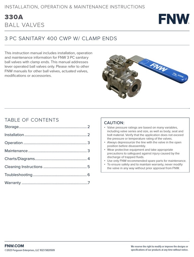
This instruction manual includes installation, operation,
and maintenance information for FNW flanged
split-body ball valves. This manual addresses lever
operated ball valves only. Please refer to other
FNW manuals for other ball valves, actuated valves,
modifications, or accessories.
CAUTION:
• Valve pressure ratings are based on many variables,
including valve series and size, as well as body, seat, and
bolt material. Verify that the application does not exceed
the pressure or temperature rating of the valves.
• Always depressurize the line with the valve in the open
position before disassembly.
• Wear protective equipment and take appropriate
precautions to safeguard against injury caused by the
discharge of trapped fluids.
• Use only FNW recommended spare parts for maintenance.
• To ensure safety and to maintain warranty, never modify
the valve in any way without prior approval from FNW.
TABLE OF CONTENTS
Storage........................................................................ 2
Installation .................................................................. 2
Operation ................................................................... 3
Maintenance .............................................................. 3
Charts/Diagrams....................................................... 4
Toubleshooting ......................................................... 6
Warranty ......................................................................7

BALL VALVES
600 & 601
FLANGED TWO-PIECE BALL VALVES
INSTALLATION, OPERATION & MAINTENANCE INSTRUCTIONS
FNW.COM We reserve the right to modify or improve the designs or
specifications of our products at any time without notice.
©2022 Ferguson Enterprises, LLC 0322 3849697
STORAGE:
ATTENTION: If the valves are not destined for immediate use, the following precautions should be taken:
• If possible, leave the valves in their packaging cases during the period of storage.
• Ball valves must remain in the open position while being stored.
• In order to prevent damage, protective plastic covers on valve ends should not be removed until immediately prior to
installation.
• It is advisable to store valves in waterproof conditions. Ball valves should be protected to safeguard against humidity,
moisture, dust, dirt, sand, mud, salt spray, sea water, or other forms of corrosive and erosive environments.
• Valves with actuators are to be stored in dry conditions.
• Valves to be stored for long periods of time should be checked by the quality control personnel or designee every six
months; every three months when valves are automated. Maintenance during this storage period can include:
- Internal surface should be inspected to check for dust or other foreign objects.
- Rust or dust must be removed by cleaning with proper solvent.
- After cleaning, ball valves must be lubricated with adequate lubricant.
- Ball valves should be operated for at least three complete cycles before installing or returning to storage.
WARNING:
To avoid personal injury to yourself, fellow workers, or damage to property from release of process fluid, before installation:
• Shut off all operating lines to the valve site.
• Isolate the valve site completely from the process.
• Release process pressure.
• Drain the process fluid from the valve site.
INSTALLATION
Note
• The ball valves may be installed in any position using standard pipe fitting practices.
• Pipe must be free of tension both during and after installation.
• The ball valves are shipped in the full open position to prevent damage of seat and ball surfaces. The valve should be kept in the open
position during installation.
• The ball valves are supplied with end caps for protecting the flange connections and the interior space of the valves. Remove the
protective covers only just prior to installation of the valve.
• There may be residual water from testing trapped between the ball and body. This can be removed by partially opening the valve,
exposing the cavity to the through port of the ball.
• If the valve was supplied with an actuator, secondary support may be necessary. Contact FNW for recommendations.
• FNW flanged ball valves are designed for mounting between ANSI flanges. It should be taken into account that a valve which is
designed for a particular flange standard cannot, under normal situations, be used with flanges from another standard. If pipeline
flanges are to be used that are not in accordance with the specifications of the order, the manufacturer should be consulted. All
standard flange seals can be used.
• ATTENTION: Do not perform welding near an installed valve. Welding in the vicinity of an installed valve can damage the valve and
cause leakage.
• CAUTION: The rotating ball can cause injury. Keep body parts away from the space between ball and body (valve interior).

BALL VALVES
600 & 601
FLANGED TWO-PIECE BALL VALVES
INSTALLATION, OPERATION & MAINTENANCE INSTRUCTIONS
FNW.COM We reserve the right to modify or improve the designs or
specifications of our products at any time without notice.
©2022 Ferguson Enterprises, LLC 0322 3849697
Before Installation
• Inspect the valve body port and associated equipment for any damage that may have occurred and for any foreign matter that may
have collected in shipping or storage. Make certain the body interior is clean.
• Inspect the pipeline and mating flanges, making sure the pipe is free of foreign material that could damage the ball or seat and the
flanges are clean and have no burrs or pits that could cause leakage.
• Cycle the valve at least twice to ensure proper operation.
Installing
• Prior to mounting the valve, flush the pipeline to remove soiling and weld residue.
• Make sure the protective end caps from the valve are removed.
• Ensure that the pipe flanges are spread sufficiently to clear valve flanges.
• With the valve in the open position, insert it, along with appropriate flange gaskets (not included), between the pipeline flanges.
• Insert appropriate size bolts and heavy hex nuts (not included) as recommended for the flange size and class.
• Verify proper alignment of all components and then tighten the flange bolts according to gasket manufacturer’s recommended
practices or standard piping practices of stipulated torque.
• ATTENTION: Do not operate the valve before flushing the pipeline. Keep the valve in the open position until flushing is complete.
Residue in the line could cause damage to the seats.
OPERATION
Note: this manual only covers the operation of manually operated valves. For operation of automated valves, consult the
manufacturer’s manual for the actuator.
• Ensure that the valve materials are compatible with the service and that the operating characteristics are below the valve’s maximum.
• Open and close the valve by turning the handle one-quarter turn (º).
• Valve is in the open position when the handle is parallel with the pipeline.
• Valve is in the closed position when the handle is perpendicular to the pipeline.
MAINTENANCE
Long life and maintenance-free of valves can be maintained under normal working conditions and in accordance with pressure/
temperature and corrosion data chart.
WARNING: Ball Valves can trap pressurized fluids in the Ball cavity in closed position.
Prior to maintenance, relieve the line pressure and put ball in open position firstly. Ball Valves can trap pressurized fluids in the valve
cavity in closed position. If the fluid is toxic, harmful, high-pressure, or dangerous mediums, please ensure the safety in making
disassembling.
Re-tighten packing
• Should a leakage occur at the gland packing, retighten the stem (gland) nut ().
• Take care that the stem nut () should not be tightened too much, Normally the leakage can be stopped by simply turning the stem
nut () by °~°.
Replacement of seats and seals.
• Disassembly
- Place the valve in half-open position and flush the line to remove any hazardous material from the valve body.
- Place the valve in close position; remove both counter flange bolts & nuts and lift valve from line.
- Remove handle nut (), handle () or actuator set, stop-lock-cap (), stem nut (), Belleville washer (), gland (), bush ().

BALL VALVES
600 & 601
FLANGED TWO-PIECE BALL VALVES
INSTALLATION, OPERATION & MAINTENANCE INSTRUCTIONS
FNW.COM We reserve the right to modify or improve the designs or
specifications of our products at any time without notice.
©2022 Ferguson Enterprises, LLC 0322 3849697
- Remove body bolt () or stud nut to allow end cap (), separate from body (), remove body gasket ().
- Make sure ball in Close position, thus, the ball () can be taken out easily from body, then take out ball seat.
- Push stem () down into the body cavity and remove, then remove stem O-ring (), packing () from the stem.
- Caution: Do not scratch the surface of ball, stem and packing and sealing parts during disassembling.
• Reassembly
- Reassembly process is reverse sequence of disassembly.
- Clean and inspect all parts, full replacement of all soft parts (seats and seals) is strongly recommended.
- Tighten the body bolt () crosswise using the stipulated torque See Table B.
- Tighten the stem nut () using the table stipulated torque See Table A.
- Cycle the valve slowly with gentle back and forth motion to build gradually to full quarter turn.
- If possible, test the valve before placing it back to line for service.
NOTE: Before installing the valve, please check whether the valve material, bolts and nuts are suitable to site work to avoid potential
safety hazards caused from corrosion and cracking of the valve body or bolts and nuts.
• After valve is used with its stems repeatedly turned for a long period, the stem packing may wear and cause leakage and pollution.
To tighten the stem nut (13) to compress the stem packing (9) from time to time to ensure the sealing performance of the valve is
recommended.
• The valve is packaged with recyclable cartons, wooden boxes, and turnover boxes in friendly environment material. Therefore, the
packaging boxes can be reused or recycled according to local regulations.
• When the ball valve is in the close position with pressurized fluid in the valve body. Please release the pipeline pressure and keep
the valve in the open position before maintenance.
• The noise of valve operation is 85dB(A)
NOTE: To destroy the valve, please refer to local laws and regulations of waste disposal.
TABLE A FIGURE FOR STEM NUT TIGHTEN
Valve Size Torque
NPS In-Lbs
/ ~
/ ~
~
-/ ~
-/ ~
~
-/ ~
~
~
~
~
~
TABLE B BODY STUD/NUT TORQUES
Size (Inch) Stud Size (Inch) Qty
Torque
In-Lbs Ft-Lbs
/ / - U NC .
/ / - U NC .
/ - UNC .
-/ / - UNC .
-/ /- UNC .
/- U N C .
-/ /- UNC .
/- U N C .
/- U N C .
/ - U N C .
/ - UNC

BALL VALVES
600 & 601
FLANGED TWO-PIECE BALL VALVES
INSTALLATION, OPERATION & MAINTENANCE INSTRUCTIONS
FNW.COM We reserve the right to modify or improve the designs or
specifications of our products at any time without notice.
©2022 Ferguson Enterprises, LLC 0322 3849697
BOLT TIGHTENING PATTERN
PARTS DIAGRAM 1
Studs Studs Studs Studs Studs
4
134 5
19 2
9
10
11
12
13
14
6
25
(3"-4")
20
7
8
18
21
23
22
15
17
16
24
SIZE:1/2"~2-1/2"
26
28
43419 5
1 2
9
10
11
12
13
14
15 16 17
24
8
7
6
20
18
21
25
22
30
Gear Box
SIZE:5"~8"
SIZE:3"~8"
SIZE:1/2"~2-1/2"
26
27
28
29

BALL VALVES
600 & 601
FLANGED TWO-PIECE BALL VALVES
INSTALLATION, OPERATION & MAINTENANCE INSTRUCTIONS
FNW.COM We reserve the right to modify or improve the designs or
specifications of our products at any time without notice.
©2022 Ferguson Enterprises, LLC 0322 3849697
TROUBLESHOOTING
Stem Leakage
• Stem leakage in the packing area may be eliminated by increasing the torque on the stem nut () in one-quarter turn increments. Do
not over tighten. Doing so can increase valve torque making it difficult to operate. If leakage persists, replace stem packing ().
Body Seal Leakage
• Check the tightness of the body nuts (). Tighten Per Table B. If leakage persists, replace the body seal ().
In Line or Seat Leakage
• Verify that the valve is in the fully closed position. If leakage persists, the valve should be disassembled and damaged parts replaced.
• Please see spec sheet for soft good repair kits.
PARTS DIAGRAM 2
4
1 3 4 5
19 2
9
10
11
12
13
14
6
25
(3"-4")
20
7
8
18
21
23
22
15
17
16
24
SIZE:1/2"~2-1/2"
26
28
43419 5
1 2
9
10
11
12
13
14
15 16 17
24
8
7
6
20
18
21
25
22
30
Gear Box
SIZE:5"~8"
SIZE:3"~8"
SIZE:1/2"~2-1/2"
26
27
28
29

BALL VALVES
600 & 601
FLANGED TWO-PIECE BALL VALVES
INSTALLATION, OPERATION & MAINTENANCE INSTRUCTIONS
FNW.COM We reserve the right to modify or improve the designs or
specifications of our products at any time without notice.
©2022 Ferguson Enterprises, LLC 0322 3849697
WARRANTY
1.1 LIMITED WARRANTY: Subject to the limitations expressed herein, Seller warrants that products manufactured by
Seller shall be free from defects in design, material and workmanship under normal use for a period of one (1) year
from installation but in no case shall the warranty period extend longer than eighteen months from the date of sale.
This warranty is void for any damage caused by misuse, abuse, neglect, acts of God, or improper installation. For the
purpose of this section, “Normal Use” means in strict accordance with the installation, operation and maintenance
manual. The warranty for all other products is provided by the original equipment manufacturer.
1.2 REMEDIES: Seller shall repair or replace, at its option, any non-conforming or otherwise defective product, upon
receipt of notice from Buyer during the Manufacturer’s warranty period at no additional charge. SELLER HEREBY
DISCLAIMS ALL OTHER EXPRESSED OR IMPLIED WARRANTIES, INCLUDING, WITHOUT LIMITATION, ALL IMPLIED
WARRANTIES OF MERCHANTABILITY AND FITNESS OR FITNESS FOR A PARTICULAR PURPOSE.
1.3 LIMITATION OF LIABILITY: UNDER NO CIRCUMSTANCES SHALL EITHER PARTY BE LIABLE TO THE OTHER FOR
INCIDENTAL, PUNITIVE, SPECIAL OR CONSEQUENTIAL DAMAGES OF ANY KIND. BUYER HEREBY ACKNOWLEDGES
AND AGREES THAT UNDER NO CIRCUMSTANCES, AND IN NO EVENT, SHALL SELLER'S LIABILITY, IF ANY, EXCEED
THE NET SALES PRICE OF THE DEFECTIVE PRODUCT(S) PURCHASED DURING THE PREVIOUS CONTRACT YEAR.
1.4 LABOR ALLOWANCE: Seller makes NO ADDITIONAL ALLOWANCE FOR THE LABOR OR EXPENSE OF REPAIRING
OR REPLACING DEFECTIVE PRODUCTS OR WORKMANSHIP OR DAMAGE RESULTING FROM THE SAME.
1.5 RECOMMENDATIONS BY SELLER: Seller may assist Buyer in selection decisions by providing information regarding
products that it manufacturers and those manufactured by others. However, Buyer acknowledges that Buyer ultimately
chooses the product’s suitability for its particular use, as normally signified by the signature of Buyer’s technical
representative. Any recommendations made by Seller concerning the use, design, application or operation of the
products shall not be construed as representations or warranties, expressed or implied. Failure by Seller to make
recommendations or give advice to Buyer shall not impose any liability upon Seller.
EXCUSED PERFORMANCE: Seller will make a good faith effort to complete delivery of the products as indicated by Seller in writing, but
Seller assumes no responsibility or liability and will accept no back-charge for loss or damage due to delay or inability to deliver, caused
by acts of God, war, labor difficulties, accidents, inability to obtain materials, delays of carriers, contractors or suppliers or any other
causes of any kind whatever beyond the control of Seller. Under no circumstances shall Seller be liable for any special, consequential,
incidental, or indirect damages, losses, or expense (whether or not based on negligence) arising directly or indirectly from delays or
failure to give notice of delay.
This manual suits for next models
21
Table of contents
Other FNW Control Unit manuals
Popular Control Unit manuals by other brands

Vertiv
Vertiv Liebert MBSM user manual

salmson
salmson Cleanskid Series Installation and starting instructions

Watts
Watts 980GD-16-19 Installation, operation and maintenance manual

Rittal
Rittal SV9343.070 Assembly and operating instructions
MX
MX Atmos Vision Fitting instructions

Linear Technology
Linear Technology DC1811B-B manual
Azbil
Azbil ACTIVAL VY5302B Specifications & instructions
Econex
Econex MDV Series Assembling and servicing instructions
Weinmann
Weinmann OXYWAY Instructions for use
EOS
EOS EmoTouch 3 Installation and operation manual
Jag
Jag FB2 Installation, operation & maintenance manual

Gan Systems
Gan Systems GS-EVB-HB-66508B-RN Technical manual
