Sloan SOLIS 8100 Series User manual

Code No. 0816641
Rev. 10 (05/23)
INSTALLATION INSTRUCTIONS FOR RETROFIT AND COMPLETE VALVE
INSTALLATION FOR SLOAN SOLIS®, SOLAR POWERED, SINGLE FLUSH
AND DUAL FLUSH WATER CLOSETS AND URINALS
SLOAN® LIMITED WARRANTY SUMMARY
Sloan Valve Company (“Sloan”), warrants its products against defects in materials and workmanship, excluding damage caused by matters beyond Sloan’s reasonable control. Instructions
for filing claims can be found in the Limited Warranty which can be obtained at www.sloan.com or by requesting a free copy by telephone at 888.756.2614. Sloan will repair or replace your
defective product, or provide a refund, as your exclusive remedy. This is only a general summary of Sloan’s Limited Warranty so it is important to note that the specific terms, conditions,
limitations and exclusions, including the duration of warranty coverage for your particular Sloan product, are contained in the actual Sloan Limited Warranty. The Limited Warranty is subject
to applicable laws in your country, state, province or other jurisdiction—and disputes arising under the Limited Warranty are to be resolved by binding arbitration unless you provide Sloan
with an opt-out notice no later than 30 days after your purchase date. In case of a conflict with this summary, the terms and conditions set forth in the complete Limited Warranty will prevail.
Sloan SOLIS®Water Closet Models can be furnished for the following:
1.1 gpf / 4.2 Lpf High Efficiency Bowls
1.28 gpf/4.8 Lpf High Efficiency Bowls
1.6 gpf/6.0 Lpf For Low Consumption Bowls
1.6 / 1.1 gpf (6.0 / 4.2 Lpf) Dual Flush Models
Sloan SOLIS®Urinal Models can be furnished for the following:
0.125 gpf/0.5 Lpf For High Efficiency Urinals
0.25 gpf/0.9 Lpf For High Efficiency Urinals
0.5 gpf/1.9Lpf For High Efficiency Urinals
1.0 gpf/3.8 Lpf For Low Consumption Urinals
1.5 gpf/5.7 Lpf For Older Siphon Jet Urinals
Please take the time to read this manual to ensure proper product
installation and longevity. Also, please visit our website to
download our most recent documentation for this product.
Prior to installing the Sloan SOLIS®flushometer, install the items listed
below as illustrated in the rough-in diagram. (New installations only.)
• Closet or Urinal fixture
• Drain line
• Water supply line
IMPORTANT:
• INSTALL ALL PLUMBING IN ACCORDANCE WITH
APPLICABLE CODES AND REGULATIONS.
• WATER SUPPLY LINES MUST BE SIZED TO PROVIDE AN
ADEQUATE VOLUME OF WATER FOR EACH FIXTURE.
• WHEN INSTALLING A FLUSHOMETER, IT IS
IMPORTANT THAT THE FLUSH MODEL MATCHES THE
REQUIREMENTS OF THE PLUMBING FIXTURE.
• FLUSH ALL WATER LINES PRIOR TO MAKING
CONNECTIONS.
The Sloan SOLIS®is designed to operate with 15 to 80 PSI (104 to 551
kPa) of water pressure. THE MINIMUM PRESSURE REQUIRED
TO THE VALVE IS DETERMINED BY THE TYPE OF FIXTURE
SELECTED. Consult fixture manufacturer for pressure requirements.
Most water closets (1.6 gallon/6 liter or lower) require a minimum flowing
pressure of 25 psi (172 kPa); some manufacturers require a higher
minimum flowing pressure.
PRIOR TO INSTALLING THE SLOAN SOLIS®FLUSHOMETER
• Slotted screwdriver to adjust control stop.
• Sloan A-50 Super-Wrench™, Sloan A-109 Plier Wrench or smooth jawed
spud wrench for couplings.
• Strap wrench (supplied) to install Sloan SOLIS®to valve body.
• 7/64” hex wrench (supplied) to secure Sloan SOLIS®cover to base plate.
• 5/64” hex wrench to secure water Supply Flange.
TOOLS REQUIRED FOR INSTALLATION
8100 Series Complete Flushometer Models
8100 Series Sloan SOLIS®valves are complete flushometers
and ideal for new installations.
RESS Series Retrofit Conversion Kit Models
RESS Sloan SOLIS®Models are used to convert existing
Flushometers to Solar Powered, Sensor Activated.
2
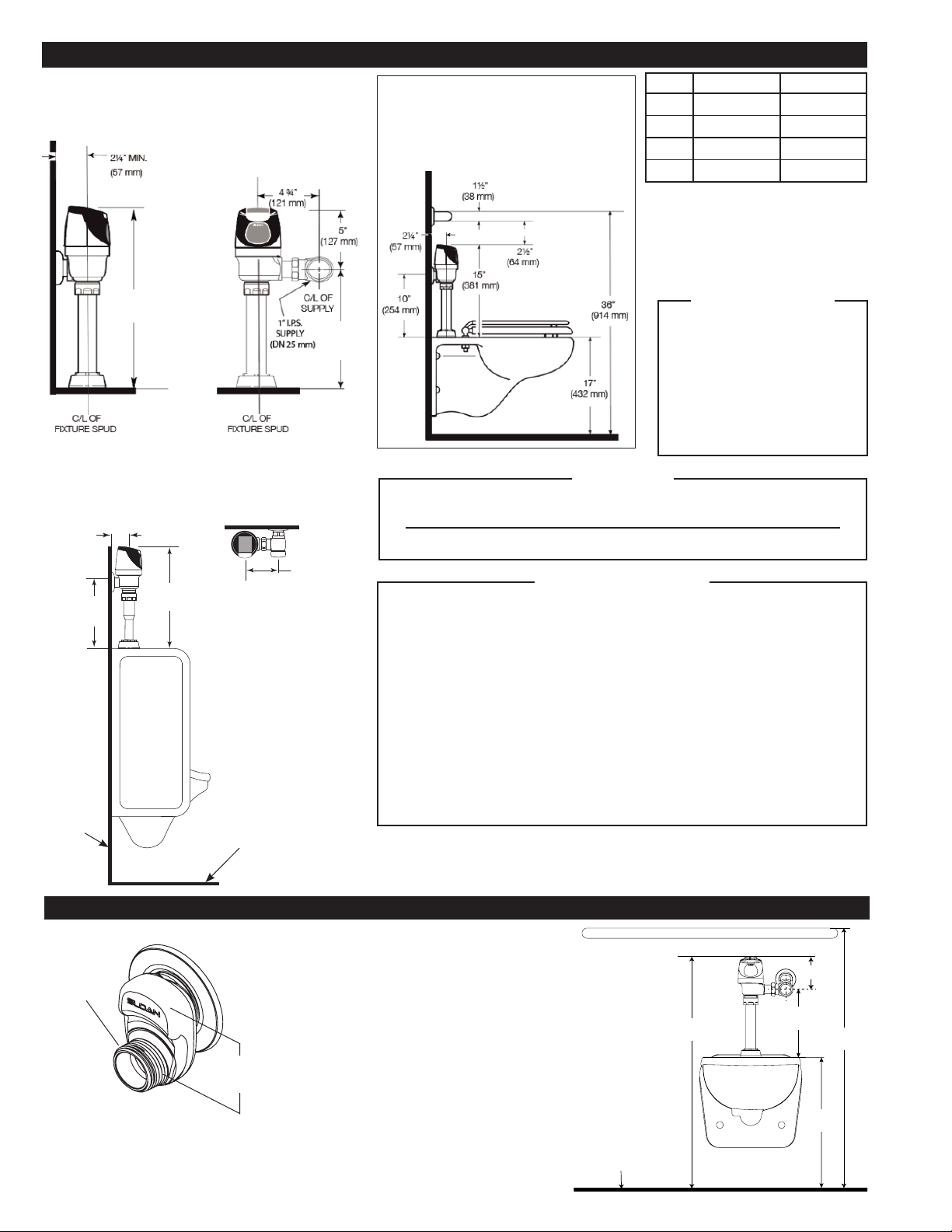
VALVE ROUGH-IN
2¼” (57 mm) MIN.
16½”
(419 mm)
C/L OF
FIXTURE
FINISHED
FLOOR
FINISHED
WALL
4¾”
(121 mm)
8180
1” I.P.S.
(25 mm DN)
SUPPLY
8186
¾” I.P.S.
(20 mm DN)
SUPPLY
11½”
(292 mm)
TYPICAL URINAL INSTALLATION
Models 8180 & 8186
Reference for RESS-U Retrofit
LAWS AND REGULATIONS PROHIBIT THE USE OF HIGHER FLUSHING
VOLUMES THAN LISTED ON FIXTURE OR FLUSHOMETER.
THE STRAP WRENCH PROVIDED WITH THE SOLIS®IS A CONVENIENCE TOOL
AND IS NOT TO BE USED TO REMOVE OR INSTALL THE FLUSHOMETER
COUPLINGS. USE STRAP WRENCH ONLY TO INSTALL THE SOLIS®LOCKING RING.
WITH THE EXCEPTION OF THE CONTROL STOP INLET, DO NOT USE PIPE
SEALANT OR PLUMBING GREASE ON ANY VALVE COMPONENT OR COUPLING!
THIS PRODUCT CONTAINS MECHANICAL AND/OR ELECTRICAL COMPONENTS
THAT ARE SUBJECT TO NORMAL WEAR. THESE COMPONENTS SHOULD BE
CHECKED ON A REGULAR BASIS AND REPLACED AS NEEDED TO MAINTAIN
THE VALVE’S PERFORMANCE.
NEVER OPEN CONTROL STOP TO WHERE THE FLOW FROM THE VALVE
EXCEEDS THE FLOW CAPABILITY OF THE FIXTURE. IN THE EVENT OF A
VALVE FAILURE, THE FIXTURE MUST BE ABLE TO ACCOMMODATE A
CONTINUOUS FLOW FROM THE VALVE.
!!! IMPORTANT !!!
Model “X” “Y”
8111†11½” (292 mm) 16½” (419 mm)
8113 16” (406 mm) 21” (533 mm)
8115‡24” (610 mm) 29” (737 mm)
8116‡27” (686 mm) 32” (813 mm)
PROTECT THE CHROME
OR SPECIAL FINISH OF
FLUSHOMETERS — DO NOT USE
TOOTHED TOOLS TO INSTALL
OR SERVICE THESE VALVES.
USE A SLOAN A-50 SUPER-
WRENCH™, SLOAN A-109 PLIER
WRENCH OR SMOOTH JAWED
SPUD WRENCH TO SECURE ALL
COUPLINGS. ALSO SEE “CARE
AND CLEANING” SECTION.
!!! IMPORTANT !!!
†For new installations, Sloan strongly
recommends the use of our Model 8111 which
has a shorter installation height.
‡Model 8115 & 8116 valves are designed for
installations where the water supply is roughed-
in 24” - 27” (610 mm - 686 mm) above the top
of the water closet.
2
When installing the Sloan SOLIS®Electronic
Flushometer in an ADA compliant stall: Per ADA
Guidelines (section 604.9.4) it is recommended that
the grab bars be split or shifted to the wide side of the
stall. For alternative installations, lower water supply
rough-in to 10” (254 mm), or use the H-1018-A 1-1/2”
offset adapter (not supplied) to lower the overall height.
The Sloan H-1018-A 1” NPT x 1-1/2” offset adapter
kit (sold separately) is designed to lower a SOLIS®
Flushometer 1-1/2” when the space above the top
of the Flushometer conflicts with grab bar clearance.
Mount the grab bar at the 36” (914 mm) maximum
allowed height (top of grab bar at 36”).
G
D
H
A
B
F
C
E
FIN. FLOOR
36”
(914 mm)
32½”
(825 mm)
5”
(127 mm)
10”
(254 mm)
17”
(432 mm)
ALTERNATIVE WATER CLOSET INSTALLATION WITH GRAB BAR
1½
(38 mm)
1” NP
T
WATER CLOSET INSTALLATION
Models 8111, 8113, 8115, 8116
Reference for RESS-C Retrofit
“X”
“Y”
Maximum adjustment of the Sloan Adjustable Tailpiece is ½” (13 mm) IN or OUT from the
standard 4¾” (121 mm) (
centerline of Flushometer to centerline of Control Stop
).
If roughing-in measurement exceeds 5¼” (133 mm), consult factory for longer tailpiece.
NOTE
FOR ADA GRAB BAR APPLICATIONS
For ADA grab Bar at 36”, use 10” rough-in
height or use H-1018-A Offset Adapter.
See the
Alternative Water Closet Installation
section below for additional information.
If you have questions about how to install your Sloan flushometer,
consult your local Sloan Representative, or contact Sloan Technical Support at
1.888.SLOAN.14 (1.888.756.2614).

3
1 - FOR COMPLETE VALVE INSTALLATION, START HERE. FOR RESS
RETROFIT INSTALLATIONS, START AT STEP 6. INSTALL OPTIONAL
SWEAT SOLDER ADAPTER (ONLY IF YOUR SUPPLY PIPE DOES NOT
HAVE A MALE THREAD)
WATER SUPPLY PIPE
FINISHED WALL
1-1/4”
(32 mm)
C/L OF
FIXTURE
SPUD
SWEAT
SOLDER
ADAPTER
AMeasure from finished wall to C/L of Fixture Spud. Cut pipe 1¼”
(32 mm) shorter than this measurement. Chamfer O.D. and I.D. of
water supply pipe.
BSlide Threaded Adapter fully onto pipe.
CSweat solder the Adapter to pipe.
WITH THE EXCEPTION OF THE CONTROL STOP INLET,
DO NOT USE PIPE SEALANT OR PLUMBING GREASE ON
ANY VALVE COMPONENT OR COUPLING!
!!! IMPORTANT !!!
AOpen Control Stop.
CClose control stop.
BTurn on water supply to flush line of any debris or sediment.
BAK-CHEK®
CONTROL STOP
COVER TUBE
IRON PIPE NIPPLE OR
COPPER PIPE WITH SWEAT
SOLDER ADAPTER
SET SCREW
SUPPLY
FLANGE
WATER
SUPPLY PIPE
SWEAT
SOLDER ADAPTER
COVER TUBE
WALL
FLANGE
AMeasure from finished
wall to first thread of
adapter or threaded
supply pipe (dimension
“X”). Cut cover tube to
this length.
BSlide cover tube over
pipe. Slide wall flange
over cover tube until
against wall.
Thread control stop onto pipe.
Tighten with a wrench.
C
Tighten set screw with a 5/64”
hex wrench. DO NOT install vandal
resistant stop cap at this time.
D
“X”
2 - INSTALL COVER TUBE, WALL FLANGE AND CONTROL STOP TO SUPPLY PIPE
3 - FLUSH OUT SUPPLY LINE
VACUUM
BREAKER
TUBE
SPUD COUPLING
NYLON SLIP
GASKET
RUBBER GASKET
SPUD FLANGE
ASlide Spud Coupling, Nylon Slip Gasket, Rubber Gasket and Spud
Flange over Vacuum Breaker Tube.
BInsert Tube into Fixture Spud.
CHand tighten Spud Coupling onto Fixture Spud.
VACUUM
BREAKER
TUBE
SPUD COUPLING
NYLON SLIP
GASKET
RUBBER GASKET
SPUD FLANGE
MODELS
8110/8111,
8115, 8116
MODEL 8180 MODEL 8186
If cutting Vacuum Breaker Tube to size, note that Critical Line (C/L)
on Vacuum Breaker must typically be 6” (152 mm) above fixture.
Consult Code for details.
NOTE
4 - INSTALL VACUUM BREAKER FLUSH CONNECTION
NOTE:
Use only Sloan
sweat adapter fully
inserted onto pipe.

CAlign flushometer body and securely tighten first the tailpiece
coupling (1), then the vacuum breaker coupling (2), and finally the
spud coupling (3). Use a wrench to tighten these couplings in the
order shown.
BAlign flushometer directly above the
vacuum breaker flush connection by
sliding the flushometer body IN or OUT
as needed. Tighten vacuum breaker
coupling by hand.
ALubricate tailpiece o-ring with water.
Insert adjustable tailpiece into control
stop. Tighten tailpiece coupling by hand.
Maximum adjustment of the Sloan Adjustable Tailpiece is
½” (13 mm) IN or OUT from the standard 4¾” (121 mm)
(centerline of Flushometer to centerline of Control Stop).
If roughing-in measurement exceeds 5¼” (133 mm),
consult factory for longer tailpiece.
NOTE
ARemove control stop cap.
CRemove outside and inside covers and old inside parts kit.
BTurn off water supply at control stop. Push valve handle
to relieve water pressure.
G-44 FRICTION RING
C/L
SUPPLY
ADJUSTABLE
TAILPIECE
C/L
FIXTURE
CONTROL STOP
O-RING
TAILPIECE COUPLING
VACUUM BREAKER
FLUSH CONNECTION
VACUUM
BREAKER
COUPLING
FLUSHOMETER
BODY
4-3/4”
(121 mm)
DRemove old handle assembly and gasket.
EInstall chrome handle cap with gasket to handle opening on
flushometer body. Tighten chrome handle cap securely.
NOTE: An extra H-553 tail o-ring is included (
in the bag with the handle
cap and gasket
) in the event leakage occurs if the valve is repositioned
during the installation of the new SOLIS®. Use only as needed.
H-553
TAIL O-RING
A
C
E
B
D
RESS SERIES
INSTALLATIONS ONLY
1
2
SPUD
COUPLING
3
VACUUM
BREAKER
REPAIR KIT
4
O-RING
The flush volume of the Sloan SOLIS®is controlled by the Regulator in the
flex tube diaphragm Kit. Regulators are identified by color.
NOTE: Never use more water than needed. Low Consumption water
closets and urinals will not function properly on excess water.
REGULATOR
(MUST BE INSTALLED
PAST O-RING)
5 - INSTALL FLUSHOMETER
6 - WHEN RETROFITTING AN EXISTING VALVE, START HERE. REMOVE COMPONENTS
FROM EXISTING FLUSHOMETER (RESS RETROFIT INSTALLATIONS ONLY)
7 - SLOAN SOLIS®FLUSH VOLUME (RESS RETROFIT INSTALLATIONS ONLY)
When installing a new Regulator on a Flex Tube Diaphragm, be sure to push
the Regulator past the O-ring when installing.
RESS SERIES
INSTALLATIONS ONLY
5
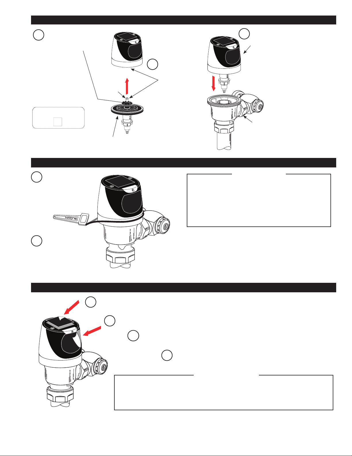
ARemove the tape located over solar panel.
DFor the first ten (10) minutes of operation, a visible light flashes in the
sensing window of the SOLIS®flushometer when a user is detected.
BRemove the tape located over sensor window.
AThread Locking Ring
onto Valve Body.
BUse Strap Wrench
provided to tightly secure
Locking Ring. Both
wrench and coupling
ring must be dry.
If retrofitting the Sloan SOLIS®onto a †Zurn®valve body, a special Locking Ring must
be used (identified by a machined groove around the ring).
Order the Sloan SOLIS®with the “Z” variation to receive the unit supplied with this Ring.
9 - TIGHTEN LOCKING RING
10 - REMOVE TAPE FROM SOLAR PANEL AND SENSOR WINDOW TO ACTIVATE
8 - ASSEMBLE FLEX TUBE DIAPHRAGM TO SOLIS ASSEMBLY
BInsert diaphragm
into the base of
the Sloan SOLIS®
Assembly. O-ring
must be fully
inserted into the
hole.
AMake sure Flush
Volume Regulator is
installed past O-ring.
VALVE
BODY
O-RING
FLEX TUBE
DIAPHRAGM
CPush diaphragm securely against
underside of Sloan SOLIS®Assembly.
Place entire Assembly onto the Valve Body.
NOTE: Sensor Lens must
face directly forward. Rotating
the Sensor to either side will
decrease the Sensor’s ability to
detect a target.
To facilitate installation, wet the
diaphragm assembly (on top or
completely).
THE LOCKING RING MUST BE INSTALLED DOWN PAST
THE VALVE BODY THREADS BY AT LEAST ONE THREAD.
IF DIFFICULTY IS EXPERIENCED INSTALLING THE
LOCKING RING, TURN THE LOCKING RING BACK AND
FORTH, EACH TIME WORKING IT FURTHER DOWN THE
THREADS. THE LOCKING RING WILL ACT AS A THREAD
CHASER IN THE EVENT THERE HAS BEEN A BUILD-UP OF
MATTER ON THE THREADS OF THE OLD VALVE BODY.
!!! IMPORTANT !!!
† The brands and/or products names referenced herein may be subject to trademark rights of their respective owners.
Use of the brands and names is for identification purposes only and does not imply affiliation with or endorsement by Sloan.
The start-up routine will be 1 minute long and allows the sensors to adapt to the surrounding environment. It is VERY
IMPORTANT that no non-permanent targets (i.e. persons, buckets, covers, etc) are present at this time. The start-up
routine consists of a long (3 seconds) BLUE light ON, followed by slow BLUE light blinking in for 1 minute. At the end of
the routine the sensor will show ONE long (2 seconds) BLUE light ON for lithium battery or TWO long (2 seconds each)
BLUE light ON pulses for alkaline to complete the routine. Only at this time can the non-permanent objects be present.
!!! IMPORTANT !!!
For SOLIS -SMT:
Document the serial number
and token number on the
label at the back of the
SOLIS assembly by taking a
photo or writing it down.
IMPORTANT: Please note
location and restroom for
each serial number for future
importing to SC Argus Pro.
CStand clear from the sensor for (1) minute to allow the unit to start-up and calibrate to
the installed environment.
Serial # SRS-XXXXXXXXXXXX
Token # XXXXXXXXXX

When required, replace batteries with four (4)
new AA-Size batteries.
NOTE: Water does not have to be turned off
to replace batteries.
Loosen the two (2) Screws on top of unit.
Remove the complete cover assembly. Lift
the sensor module from its plate. Unplug the
solenoid connector from battery compartment
cover. Loosen the retaining screw on
battery compartment cover. Remove battery
compartment cover and old batteries.
Install four (4) new AA-Size batteries exactly as illustrated. Install battery
compartment cover and secure with retaining screw. Make certain that
battery compartment cover is fully compressed against gasket to provide
a seal; DO NOT overtighten. Plug the solenoid connector into the battery
compartment cover. Reinstall the sensor module onto the Plate. Reinstall the
complete cover assembly onto the plate. Tighten the two (2) screws on top
of the unit.
6
COVER
ASSEMBLY
SENSOR
MODULE
PLATE
BATTERY
COMPARTMENT
COVER
SOLENOID CONNECTOR RECEPTACLE
SENSOR
MODULE
RETAINING
SCREW
BATTERY REPLACEMENT
BStand in front of Sensor
for sixteen (16) seconds
CStep away from Sensor
and listen for “CLICK.”
ATest Sensor with Cover in place.
The Sloan SOLIS®has a factory set sensing range:
Water Closet Models - 22” to 42” (559 mm to 1067 mm)
Urinal Models - 15” to 30” (381 mm to 762 mm)
THE FACTORY SETTING SHOULD BE SATISFACTORY FOR MOST
INSTALLATIONS. IF A RANGE ADJUSTMENT IS REQUIRED, REFER TO
THE RANGE ADJUSTMENT INSTRUCTIONS.
1. A continuous, INVISIBLE light beam is emitted from the Sloan SOLIS®sensor.
2. As the user enters the beam’s effective range, 22 to 42 inches (559 mm to 1067 mm) for closet
installations and 15 to 30 inches (381 mm to 762 mm) for urinal installations, the beam is reflected
into the Scanner Window to activate the Output Circuit. Once activated, the Output Circuit continues
in a “hold” mode for as long as the user remains within the effective range of the sensor. For Dual
Flush models, if the user stays longer than 65 seconds, a full flush will automatically initiate when the
user leaves. For Single Flush models, once the user steps away, a full flush will automatically initiate.
3. For Dual Flush models, once a user is detected, if the user leaves in 65 seconds or less, a reduced flush will automatically initiate. The circuit
automatically resets and is ready for the next user. For Single Flush models, when the user steps away, this initiates a full flush. The circuit automatically
resets and is ready for the next user.
4. In addition to the above the Sloan SOLIS®urinal incorporates a standard deferred flushing mode feature that accommodates the high volume usage seen
in stadiums or similar high attendance facilities.
DInstall control stop cap onto control stop. For RESS retrofit applications, reuse stop cap from existing valve. In complete valve installations, a new stop
cap is provided. Follow the instructions packaged with the free spinning vandal resistant stop cap.
BActivate flushometer
by placing hand in
front of Sloan SOLIS®
Sensor Lens for ten
(16) seconds (
or press
override button
) and
then moving it away.
AOpen control Stop COUNTERCLOCKWISE at least ½ turn from
closed position.
CAdjust control stop after each flush until the rate of flow delivered
properly cleanses the fixture.
URINAL
CLOSET
11 - TEST SENSOR OPERATION
12 - ADJUST CONTROL STOP AND INSTALL VANDAL RESISTANT STOP CAP
OPERATION
SLOAN FLUSHOMETERS ARE ENGINEERED FOR QUIET
OPERATION. EXCESSIVE WATER FLOW CREATES NOISE,
WHILE TOO LITTLE WATER FLOW MAY NOT SATISFY THE
NEEDS OF THE FIXTURE. PROPER ADJUSTMENT IS MADE
WHEN PLUMBING FIXTURE IS CLEANSED AFTER EACH
FLUSH WITHOUT SPLASHING WATER OUT FROM THE LIP
AND A QUIET FLUSHING CYCLE IS ACHIEVED.
!!! IMPORTANT !!!
THE CONTROL STOP SHOULD NEVER BE OPENED TO THE
POINT WHERE THE FLOW FROM THE VALVE EXCEEDS
THE FLOW CAPABILITY OF THE FIXTURE. IN THE EVENT
OF A VALVE FAILURE, THE FIXTURE MUST BE ABLE TO
ACCOMMODATE A CONTINUOUS FLOW FROM THE VALVE.
!!! IMPORTANT !!!
NEVER INSTALL MIXED BATTERY TYPES: (CARBON-ALKALINE-
LITHIUM) PRIMARY AND SECONDARY CELLS (NON-RECHARGEABLE VS
RECHARGEABLE). REPLACE ALL 4 BATTERIES AT THE SAME TIME WITH
FRESH BATTERIES. FAILURE ON THE ABOVE CAN REDUCE BATTERY
LIFE, CAUSE BATTERY LEAKAGE, AND RESULT IN PRODUCT DAMAGE.
!!! IMPORTANT !!!
7
DO NOT USE abrasive or chemical cleaners to clean flushometers as they may dull the luster and attack the chrome or special decorative finishes. Use
ONLY mild soap and water, then wipe dry with clean cloth or towel. DO NOT spray cleaner directly onto the flushometer; instead, spray into a clean cloth
and then wipe down the flushometer. While cleaning the bathroom tile, the flushometer should be protected from any splattering of cleaner. Acids and
cleaning fluids can discolor or remove chrome plating.
RANGE ADJUSTMENT (ADJUST ONLY IF NECESSARY)
CARE AND CLEANING
TROUBLESHOOTING GUIDE
LAWS AND REGULATIONS PROHIBIT THE USE OF HIGHER
FLUSHING VOLUMES THAN LISTED ON FIXTURE OR
FLUSHOMETER.
!!! IMPORTANT !!!
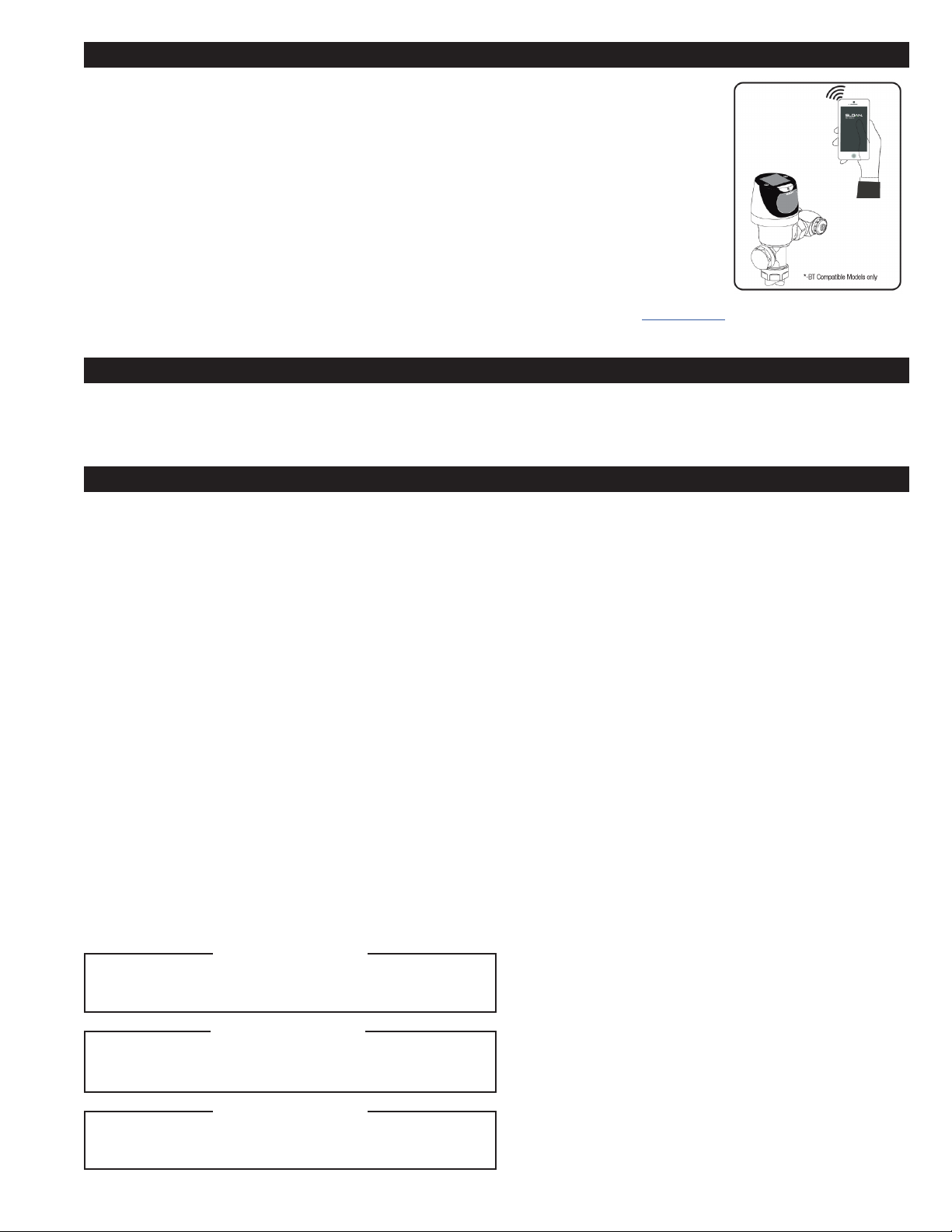
NOTE: For -BT models
only, to automatically
check battery strength,
troubleshoot, diagnose and
report flushometer issues
with a wireless device, use
the Sloan Connect APP. The
APP is available free-of-
charge at the Apple iPhone
APP store for iOS devices
or the Google Play APP
store for Android devices.
For more information about
the APP and its capabilities
please visit www.sloan.com.
The Sloan SOLIS®has a factory set sensing range:
Water Closet Models - 22” to 42” (559 mm to 1067 mm)
Urinal Models - 15” to 30” (381 mm to 762 mm)
The factory setting should be satisfactory for most installations.
NOTE: Water DOES NOT have to be turned off to adjust range.
RANGE ADJUSTMENT PROCEDURE
For the first ten (10) minutes of operation, a visible light flashes in the sensing Window
of the Sloan SOLIS®flushometer when a user is detected. This visible light feature can
be reactivated after ten (10) minutes by opening and closing the battery compartment
door. Check the range by stepping toward the unit until the light flashes, indicating the
sensor’s maximum detection limit.
Always Determine the Sensing Range with Metal Cover and Lens Window On
Top of the Unit.
To recalibrate the sensor, touch and hold the override button for 30 seconds, once the
Blue LED blinks every second, and release. Stand at desired distance, LED should blink
once every 2 seconds for 30 seconds). The setting mode will run for one (1) minute.
1. Sensor Flashes Continuously Only When User Steps Within Range.
A. Unit in Start-Up mode; no problem. This feature is active for the first ten
(10) minutes of operation.
2. Valve Does Not Flush; Sensor Not Picking Up User.
A. Range too short; increase the range.
3. Valve Does Not Flush; Sensor Picking Up Opposite Wall or Surface, or
Only Flushes When Someone Walks By. Light Flashes Continuously for
First 10 Minutes Even with No One in Front of the Sensor.
A. Range too long; shorten range.
4. Valve Does Not Flush Even After Adjustment.
A. Range Adjustment Potentiometer set at full “max” or full “min” setting. Re-
adjust Potentiometer away from full “max” or “min” setting.
B. Batteries completely used up; replace batteries.
C. Problem with Electronic Sensor Module; replace Electronic Sensor Module.
Try swapping module with working unit to test module function.
D. Are there audible clicks from the solenoid?
NO: check for solenoid plugged into module; possibly solenoid stuck in
closed position, replace solenoid.
YES: check solenoid for over-tightening, check to make sure locking ring
was secured properly.
E. Module is working, and solenoid clicking, loosen and re-tighten locking ring;
check diaphragm for perforations in diaphragm disc; replace.
5. Unit Flashes 4 Quick Times When User Steps Within Range.
A. Batteries low; replace batteries.
6. Valve Does Not Shut Off.
A. Bypass Orifice in Diaphragm is clogged with dirt or debris, or Bypass
is clogged by an invisible gelatinous film due to “over-treated” water.
Remove flex tube diaphragm and wash under running water or
replace.
NOTE: SIZE OF ORIFICE IN THE BYPASS IS OF UTMOST
IMPORTANCE FOR THE PROPER METERING OF WATER BY THE
VALVE. DO NOT ENLARGE OR DAMAGE THIS ORIFICE. REPLACE
FLEX TUBE DIAPHRAGM IF CLEANING DOES NOT CORRECT THE
PROBLEM.
B. Dirt or debris fouling stem or flex tube diaphragm. Remove flex tube
diaphragm and wash under running water or replace.
C. O-ring on stem of flex tube diaphragm is damaged or worn. Replace
O-ring if necessary EBV-83 O-Ring 1/8 X 1/4 X 1/16 (5325056).
D. Problem with electronic sensor module; replace sensor module. Try
swapping module with working unit to test module function
E. Are there audible clicks from the solenoid?
NO, possibly solenoid stuck open position, replace solenoid.
YES, check solenoid properly screwed into inside cover, check to
make sure locking ring was secured properly.
F. If module is working, and solenoid clicking, check diaphragm for
perforations in diaphragm disc; replace.
7. Not Enough Water to Fixture.
A. Wrong flush volume regulator installed in flex tube diaphragm kit.
Install the correct Regulator.
B. Wrong SOLIS®model installed; i.e., 1.0 gpf urinal installed on 3.5
gpf closet fixture. Replace with proper Sloan SOLIS®model.
C. Enlarged by-pass in diaphragm. Replace flex tube diaphragm.
D. Control Stop not adjusted properly. Readjust control stop.
E. Inadequate volume or pressure at supply. Increase water pressure or
supply (flow) to valve. Consult factory for assistance.
8. Too Much Water to Fixture.
A. Wrong flush volume regulator installed in flex tube diaphragm Kit.
Install the correct regulator.
B. Control Stop not adjusted properly. Readjust Control Stop.
C. Wrong Sloan SOLIS®model installed; i.e., 3.5 gpf Model installed
on 1.0 or 1.5 gal. Urinal fixture. Replace with proper Sloan SOLIS®
model.
D. Dirt in Diaphragm Bypass. Clean under running water or replace Flex
Tube Diaphragm.
NOTE: Troubleshooting also applies to the Sloan SOLIS Urinals.
WHEN SERVICING SOLENOID, ROTATING LOCKING RING,
SERVICING DIAPHRAGM, SERVICING VACUUM BREAKER OR
SPUD, TURN OFF WATER SUPPLY AT STOP.
!!! IMPORTANT !!!
-SMT models require SC Argus Portal equipment and subscription. Please contact your SC Argus Pro Sales Representative or Sloan
Technical Support. For Troubleshooting and Replacement of SOLIS -SMT units, please consult the SOLIS Repair Parts & Maintenance Guide.
MORE FREQUENT ROUTINE MAINTENANCE MAY BE
REQUIRED OF THE FLUSHOMETER DUE TO THE CHEMICAL
PROPERTIES OF RECLAIMED WATER.
!!! IMPORTANT !!!

SLOAN • 10500 SEYMOUR AVENUE • FRANKLIN PARK, IL 60131
Phone: 1-800-982-5839 or 1-847-671-4300 • Fax: 1-800-447-8329 or 1-847-671-4380 • sloan.com
© 2023 SLOAN VALVE COMPANY Code No. 0816641 – Rev. 10 (05/23)
The information contained in this document is subject to change without notice.
ITEM # PART # DESCRIPTION
Items Included with RESS Retrofit and Complete Sloan SOLIS®Valves
1EBV-304-A* Cover/Sensor/Assembly - Closet SOLIS Electronic Single
EBV-320-A Cover/Sensor/Assembly (†Zurn®) - Closet SOLIS Single
EBV-306-A* Cover/Sensor/Assembly - Urinal SOLIS Single
EBV-321-A Cover/Sensor/Assembly (†Zurn®) - Urinal SOLIS Single
EBV-379-A* Cover/Sensor/Assembly - Closet SOLIS 1.1 gpf Single
WES-24-A* Cover/Sensor/Assembly - Closet SOLIS Dual
EBV-328-A* Cover/Sensor/Assembly - Urinal 0.25 gpf SOLIS Single
EBV-385-A* Cover/Sensor/Assembly - Urinal 0.125 gpf SOLIS Single
2EBV-309-A Cover Assembly - SOLIS Electronic Single Button Flush
EBV-311-A Cover Assembly - SOLIS Electronic Dual Flush
3EBV-14 Locking Ring
EBV-30 Locking Ring - for †Zurn®valves
4EBV-312-A-C Sensor Assembly SOLIS - Water Closet
EBV-312-A-U Sensor Assembly SOLIS - Urinal
EBV-388-A Module - SOLIS - 0.125 gpf Urinal
EBV-382-A Module - SOLIS - 1.1 gpf Single Button Flush
WES-33-A Module - SOLIS - Water Closet (Dual Flush)
5EBV-134 Cover Rest Plate
6EBV-145-A Inside Cover Assembly (includes solenoid)
7EBV-136-A Solenoid
8† † Flex Tube Diaphragm Assembly
9† † Flush Volume Regulator
10 EBV-1017-A Handle Cap
11 EBV-91 Range Adjustment Tool
12 EBV-22 Strap Wrench
13 EBV-137 7/64” Hex Wrench
ITEM # PART # DESCRIPTION
Items Included with Complete Sloan SOLIS®Valves Only
14 H-633-AA 1” (25 mm) Sweat Solder Kit
H-636-AA ¾” (19 mm) Sweat Solder Kit
15 H-700-A 1” (25 mm) Bak-Chek®Control Stop
H-700-A ¾” (19 mm) Bak-Chek®Control Stop
16 H-1010-A Vandal Resistant Stop Cap
17 EBV-36-A Valve Body
17A H-1015-A Flow Control (Not Shown) (Urinal 0.5, 0.25, 0.125 gpf)
18A V-600-AA 1½” (38 mm) x 10½” (229 mm) Vacuum Breaker
(Model 8110/8111)
V-600-AA 1½” (38 mm) x 15” (381 mm) Vacuum Breaker
(Model 8113)
V-600-AA 1½” (38 mm) x 23” (584 mm) Vacuum Breaker
(Model 8115)
V-600-AA 1½” (38 mm) x 26” (660 mm) Vacuum Breaker
(Model 8116)
18B V-600-A 3” (76 mm) Vacuum Breaker Assembly
18C V-600-AA 1¼” (32 mm) x 10½” (229 mm) Vacuum Breaker
(Model 8180)
18D V-600-AA ¾” (19 mm) x 10½” (229 mm) Vacuum Breaker
(Model 8186)
19 F-109 1½” (38 mm) Elbow Flush Connection
20A F-5-AT 1½” Spud Coupling Assembly (Water Closet Models)
20B F-5-AU 1¼” Spud Coupling Assembly (Model 8180)
20C F-5-AW ¾” Spud Coupling Assembly (Model 8186)
15
16
14
18A
2
18B 18D
20A
20B 20C
3
1
5
6
7
8
17
12
11
9
13
4
10
20A
18C
19
PARTS LIST
Sloan SOLIS®valve models feature Sloan’s exclusive flex tube
diaphragm for the ultimate in valve performance, reliability and
chloramines resistance.
FLEX TUBE DIAPHRAGM ASSEMBLY (#8)
FCC INFORMATION TO USERS
This equipment has been tested and found to comply with the limits for a class B
digital devices, pursuant to Part 15 of the FCC Rules. These limits are designed to
provide reasonable protection against harmful interference in a residential installation.
This equipment generates, uses, and can radiate radio frequency energy and, if not
installed and used in accordance with the instruction manual, may cause harmful
interference to radio or television reception, which can be determined by turning the
equipment off and on, the user is encouraged to try to correct the interference by one
or more of the following measures:
• Reorient or relocate the receiving antenna
• Increase the separation between the equipment and receiver
• Connect the equipment into an outlet on a circuit different from that to which the
receiver is connected
• Consult the dealer or an experienced radio/TV technician for help
† † Flow volume varies with valve model and desired flush volume. Consult the Repair
Parts & Maintenance Guide for replacement part numbers.
*-BT Sloan Connected Product Models available.
For -SMT (
SC Argus models
) consult local Rep or contact Sloan Technical
Support. For Troubleshooting and Replacement of SOLIS -SMT units, please
consult the SOLIS Repair Parts & Maintenance Guide.
† The brands and/or products names referenced herein may be subject to trademark rights of their
respective owners. Use of the brands and names is for identification purposes only and does not
imply affiliation with or endorsement by Sloan.
Manufactured in the U.S.A. by Sloan Valve Company under one or more of the following patents:
U.S. Patents: D598,975; D599,436; 7,124,997. Other Patents Pending. BAK-CHEK®, PARA-FLO®,
PERMEX®, TURBO-FLO®.
This manual suits for next models
3
Table of contents
Other Sloan Control Unit manuals

Sloan
Sloan Optima ETF-80 User manual

Sloan
Sloan TRUFLUSH TRF 8900-CP User manual

Sloan
Sloan 152 ES-S TMO SWB User manual

Sloan
Sloan G2 Optima Plus Operating manual

Sloan
Sloan NAVAL 110 User manual

Sloan
Sloan Optima Plus EBV-500-A User manual

Sloan
Sloan G2 Optima Plus Operating manual

Sloan
Sloan 152 ES-S TMO SWB User manual
Popular Control Unit manuals by other brands

Emerson
Emerson Varec 5010 Series Installation, operation and maintanance instructions

Curtiss-Wright
Curtiss-Wright PMC-605 user manual

Honeywell
Honeywell V5013N Product data

ATI Technologies
ATI Technologies QC-11HM manual

Horton
Horton C9150-3 Setup instructions

Avalue Technology
Avalue Technology ESM-KBLU user manual


