Creative Lighting Solutions CLS Atmosphere LED panel User manual
CLS Manuals
CLS Atmosphere LED-panel
CLS Manuals
CLS Atmosphere LED panel
www.cls-led.com
version 1.2 August 2009
www.cls-led.com
- 1 - - 2 -
CLS Atmosphere LED panel
Included items
The CLS Atmosphere is shipped in one package containing the following items:
• 1 CLS Atmosphere panel • 1 RJ45 data cable
• 1 AC power cord • 2 AC power end caps
• 4 Wall mount adapters • 1 user manual
Optional Accessories
• Handheld remote controller (item nr. 872305)
• RJ45-XLR 3p male & power cable (item nr. 872307)
• Cat 5 cable 2.0 meter (item nr. 706667)
• Cat 5 cable 5.0 meter (item nr. 706668)
• Cat 5 cable 10.0 meter (item nr. 706669)
• Cat 5 cable 20.0 meter (item nr. 706672)
Note: It is important to read this manual before you install this product.
The Atmosphere panel offers:
• 4 controllable RGB segments.
• High efficiency LED light source
• Decorative housing
• Rich saturated colors.
SAFETY INFORMATION
Warning! This product is for professional use only, not for domestic use. Read this manual before
powering up or installing the CLS Atmosphere Panel. Follow the instructions listed below and
observe all warnings in this manual.
Protection from electric shock
• Disconnect the fixture and from AC power before installing, dismounting or maintaining the unit.
• Make sure all connectors are connected properly.
• Always use end caps on non used 2 pole female power connectors.
• Use only a source of AC power that complies with local building and electrical codes and has both
overload and ground-fault protection.
• Do not expose the fixtures to rain or moisture.
• Refer all service to a qualified technician.
Thank you for choosing the CLS Atmosphere Panel. The Atmosphere panel is a fixture which uses LED color
mixing to create a color changing surface, in a 4 segment configuration. With this technique it is possible to create
a wide range of colors and patterns, making this unit suited for a wide range of decorative and architectural
applications.
CLS Manuals
CLS Atmosphere LED-panel
www.cls-led.com
- 3 - - 4 -
CLS Atmosphere LED panel
Protection from burns and fire
• Provide a clearance of at least 26mm at the back of the unit.
• Do not install the CLS Atmosphere Panel near a heat source.
• Do not install this CLS Atmosphere Panel in a corrosive, flammable or explosive area.
• Do not modify the CLS Atmosphere Panel, or install other than genuine parts.
• Do not operate the CLS Atmosphere Panel if the ambient temperature exceeds 40 ºC.
Protection from injury due falls
• Verify that all covers and mounting hardware is securely fastened
• Block access below the work area whenever installing or removing the fixture.
INSTALLATION
This section describes in general terms how to install the fixture, and to connect it to AC power,
and to set up a data link (for multiple units only)
Installing the fixture
There are 2 ways of installing the Atmosphere panel.
• Floor mount: Place the Atmosphere panel on a flat surface, facing the
back side, with the power cable's up. Pull out the big metal support at
the back of the unit, then pull out the small metal support underneath,
fold it out and place the big support in one of the cut-outs on the small
support. Adjust the angle by repositioning the big support.
• Wall mount. Locate the 4 U-holes at the back of the unit. Mount the 4
wall mount adapters on a flat surface on the wall at the right spacing.
Mount the Atmosphere on the 4 adapters, with the power cable's at
the top side.
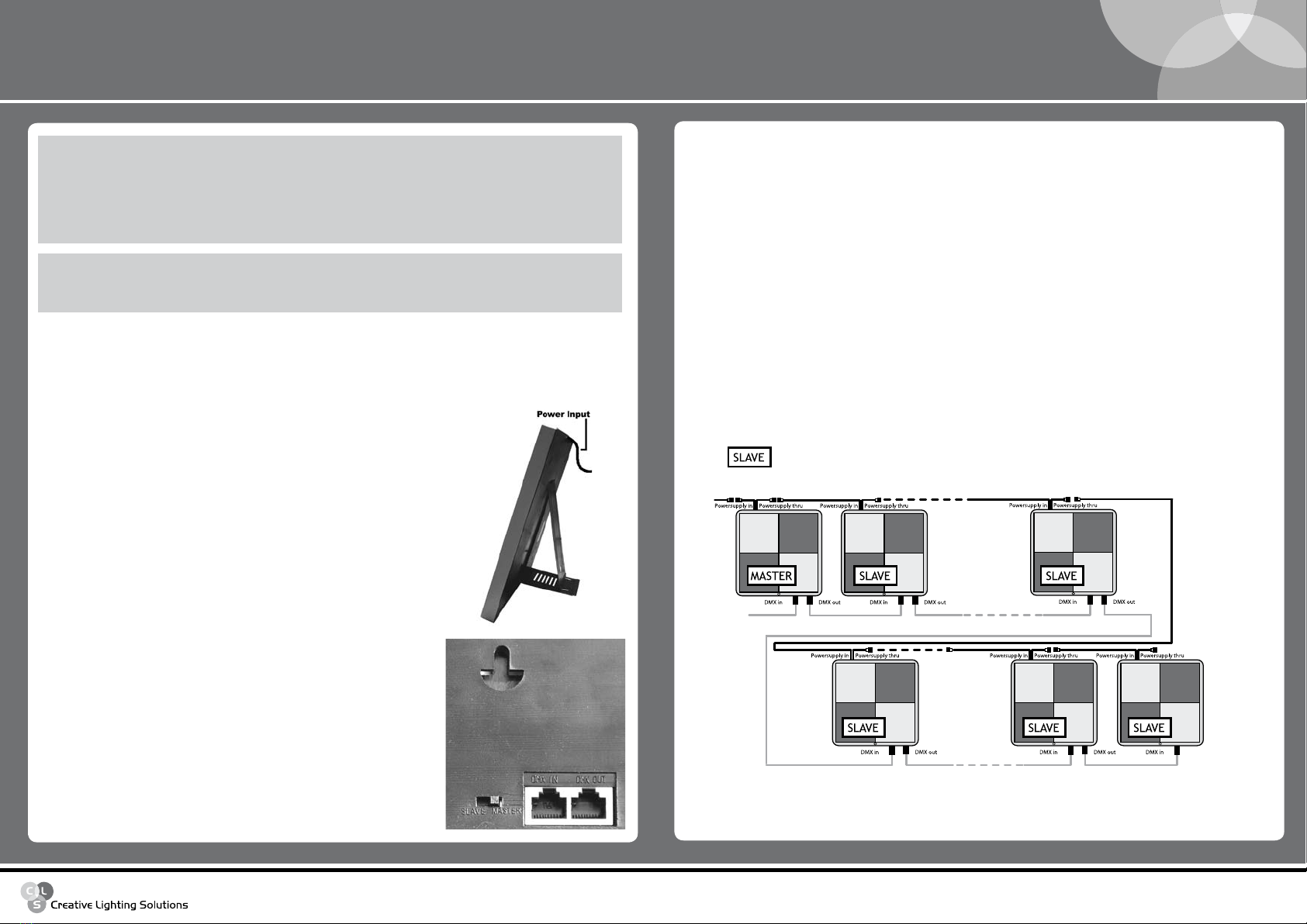
AC power
You can power the Atmosphere panel with the supplied power cable.
• First you unscrew the end cap of the power cable. Then plug the male
AC connector of the Atmosphere panel in the female AC connector of the
power cord.Tighten the connection ring on the connectors firmly.
• Multiple units can be wired in series by connecting the female
connector of the first unit to the male connector on the second, and
so on. Be sure to mount the end cap on the last unit in a link. Never
connect more than 32 units in series on one 16 amps breaker circuit
to avoid peakloads due to high inrush currents.
• Now you can plug the units in a grounded AC wall outlet.
U-hole
Master/Slave Switch
DMX in - DMX out
DATA LINKING MULTIPLE FIXTURES
You need to create a data link if you want to:
• Run multiple Atmosphere panels in a synchronous way using the optional remote control.
• Run multiple Atmosphere panels in a synchronous way in stand alone mode.
• Control one or more fixtures by a DMX controller.
The Atmosphere panel can be data-linked by using the RJ45 input and output connectors at the backside of
the unit.
To set up a data link you have to take the following steps
• Disconnect all the units from the AC supply.
• Connect the RJ45 output of the first fixture to the RJ45 input of the next fixture by using the Cat5 cable
which is supplied with every unit.
• Continue connecting fixture's RJ45 output to next fixture's RJ45 input.
• A maximum of 32 units can be connected in this way.
• Never connect other DMX products with RJ45 connectors directly to an Atmosphere link, but use
dedicated adapters for these purposes!
CLS Manuals
CLS Atmosphere LED-panel
www.cls-led.com
- 5 - - 6 -
CLS Atmosphere LED panel
DMX-OPERATION
The atmosphere panel may be controlled and operated by devices which send DMX according to the USITT
DMX 512 standard. For specific control values see the DMX Protocol on page 5.
Connecting to a DMX controller
To connect a DMX 512 controller to the atmosphere panel(s) you need a RJ45-XLR 3p male + power cable,
which can be ordered separately as item number 872307. This cable has to be connected to the DMX
output of the controller and the first Atmosphere panel, and will also replace the power cord of that fixture.
To connect this cable you have to take the following steps:
• Disconnect the Fixture(s)from your grounded AC power outlet.
• Disconnect The power cable of the first fixture by unscrewing the connection ring and unplugging it.
• Connect the Female AC connector of the Data + Power cable to the Atmospheres’ male AC connector.
• Connect the RJ45 connector to the RJ45 Input. Never swap the input and output RJ45 cables!
• Now address the fixtures as described in the DMX addressing section of this manual.
If you want to control more than 32 units with a DMX controller, you will have to use an active DMX
splitter, and set up each of it’s outputs as described above.
DMX-ADDRESSING
To control the Atmosphere panels with a DMX controller, you will need to set the start address of each unit.
This can only be done by using the optional remote controller (item number 872305). Each Atmosphere
panel uses a maximum of 13 channels, to allow each of it's 4 segments to have individual RGB control.
To allow individual DMX control over each of the Atmosphere panels, you have to make sure there are no
overlapping addresses!
To set the DMX address of the each fixture you have to take the following steps
• Disconnect the fixture from AC power.
• Unplug both RJ45 connectors!
• Set the mode switch to master.
• Power up the fixture.
• Aim the remote at the infrared receiver at the front of the panel
• Press the address set button on the remote once..(a beep sound will confirm remote reception
on each key pressed)
• The current DMX address will be visible on the led display at the back side of the unit.
• Set the DMX address by pressing the G + or G - down button.
• Set the mode switch back to slave.
• Disconnect the fixture from AC power.
• Reconnect the RJ45 input and output cables.
• Power up the fixture.
Repeat these steps for each fixture in the DMX link.
STAND-ALONE OPERATION
The Atmosphere panel can be used stand alone. In this mode it will generate random patterns.
To set a single unit to stand alone you will have to take the following steps
• Disconnect the fixture from AC power.
• Set the mode switch of the fixture to master.
• Make sure that none of the RJ45 connectors are connected.
• Power up the fixture.
Now the Atmosphere panel will generate patterns and colors in a random way. If you want more control over
these patterns, you will need the optional remote control.
To set Multiple linked fixture's stand alone, you will have to take the following steps
• Disconnect all the fixtures from AC power
• Identify the first fixture in the link by checking which fixture has only the RJ45 out connector plugged in.
• Set the mode switch of this fixture to master
• Set all the mode switches of the other connected fixture's to slave.
• Power up all the fixtures
Now the Atmosphere panels will generate patterns and colors in sync to the first fixture. If you want more
control over these patterns, you will need the optional remote control.
!
WARNING
ATTENTION!
If yOu sET mOrE ThAN ONE fIxTurE IN A lINk As mAsTEr ThE
pANEls wIll bE dAmAgEd!

CLS Manuals
CLS Atmosphere LED-panel
www.cls-led.com
- 7 - - 8 -
CLS Atmosphere LED panel
ATTENTION!
ThE pANEl lAyOuT chANNEl Is AlwAys physIcAlly ON
chANNEl 1 IN ThE dmx lINE. IT Is NOT pOssIblE TO chANgE
ThIs. bE surE NOT TO usE ThIs chANNEl fOr ANy OThEr
fIxTurE! If yOu sET ThE AddrEss Of ThE fIxTurE fOr ExAmplE
ON 100 yOu wIll hAvE ThE pANEl lAyOuT chANNEl sTIll AT
AddrEss 1 ANd ThE fIrsT sEgmENTs' rEd chANNEl ON chANNEl
101. ThIs mEANs ThAT yOu cAN AddrEss All ExcEpT ThE fIrsT
ATmOsphErE pANEl IN ThE lINk wITh A spAcINg Of 12 chANNEls,
buT hAvE AN OffsET Of +1. TypIcAl sTArT AddrEssEs ArE: 1,
13, 25, 37, 49 ANd sO ON.
!
WARNING
2007 CLS-LED BV. All rights reserved. Information subject to change without notice, CLS-LED BV and all affiliated companies disclaim liability for
injury, damage direct or indirect loss, consequential or economic loss or any other loss occasioned by the use of, inability to use or reliance on
the information contained in this manual. No part of this manual may be reproduced, in any form or by any means, without permission in
writing from CLS-LED BV. Other legal information can be found in our General conditions to be found on the back of your CLS-LED BV invoice
or on our website www.cls-led.com/Conditions.pdf
TECHNICAL SPECIFICATIONS
LED: Top LEDs
Number of LED's: 40 red, 36 green, 36 blue
Input voltage: 100 ~ 240 VAC
Power consumption: Max. 10 VA
DMX-input: RJ45 connectors
Housing: Plastic cover
Measurement: 500 x 500 x 37 mm (hxwxd)
Weight: 4,8 kg
IP value: IP20
Working temperature: -20 ºC till + 40 ºC
Multiple connection
Possiblities on a fixture
Installation depth
In centimeters
Swivel
Fixture is horizontally rotatable,
indicated in degrees
Swivel
Fixture is vertically rotatable,
indicated in degrees
Mounting hole
In centimeters
Application area
Indoor or outdoor
Application area
Floor, wall or ceiling
Protection class
One, two or three
350º
350°
Cable length
Maximum cable attached
on the fixture in centimeters
Lifespan
Of the light source in hours
Driver
Inclusive or exclusive
Pressure
Maximum pressure on
the fixture per kg/cm2
Weight
In gram/kilogram
Curve
Minimal bending curve
in centimeters
Driver
Incl.
10.000 h
Driver
Excl.
200 cm
6 cm
LED pitch
Pitch between the
LEDs in millimeters
20 mm
15kg/cm2
4x4 cm
4 cm
4 cm
4 cm
4 cm
List of symbols
Other Creative Lighting Solutions Lighting Equipment manuals

Creative Lighting Solutions
Creative Lighting Solutions Dennis RGB User manual

Creative Lighting Solutions
Creative Lighting Solutions FOCUS COMPACT User manual

Creative Lighting Solutions
Creative Lighting Solutions LED Flexible Ribbon Strip Lighting User manual

Creative Lighting Solutions
Creative Lighting Solutions CLS MTD4 User manual


