manuals.online logo
Brands
  1. Home
  2. •
  3. Brands
  4. •
  5. SloanLED
  6. •
  7. Lighting Equipment
  8. •
  9. SloanLED LEDStripe User manual

SloanLED LEDStripe User manual

LEDStripe
Installation Guide for 701189-C-(X)
PAGE 1 OF 4
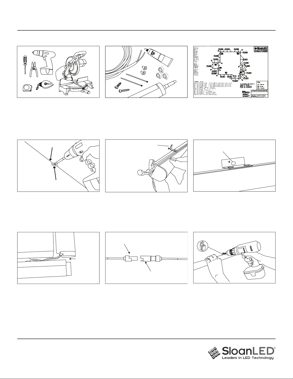
7. Corners: Corners should be installed with
one section slightly overlapping the other
leaving a minimum 0.25" (6 mm) space.
Optional corner covers can be snapped
into place.
8.
Connect pieces together: Make sure that tab is aligned
with locking clip. Once connected, hide wires at the back
of the LEDStripe in the mounting track. Use joint covers to
cover. CAUTION: To maintain the integrity of end caps and
prevent water penetration around wires, do not pull or tightly
bend wires or allow tension between wire connections.
ATTENTION: Pour maintenir l’intégrité des capuchons
d’extrémité et empêcher la pénétration d’eau autour des ls,
ne tirez pas ou ne pliez pas fermement les ls ou ne laissez
pas la tension entre les connexions des ls.
0.5"
(6 mm)
gap
Optional slide and mount rectangle
mounting buttons: (not included) are available
for hard to mount areas. Slide button onto the
back of the LEDStripe and use pan head screw
to secure to the wall.
Small connector
Large connector
4. Install mounting buttons: Snap a chalk line on
surface for mounting. Space mounting button 1.5"
(38 mm) from the end of each LEDStripe section and
every 24" (610 mm) on center throughout the length of
each LEDStripe section. For custom bends and tight
corners, see Step 9 for installation, and use a mounting
button every 12" (305 mm).
6. Secure section in place: Use #8 pan head
screws to secure center bracket once all
sections are located on the mounting surface
5. Install LEDStripe sections onto buttons: Slide or Snap
LEDStripe sections onto mounting buttons with center
bracket facing up. NOTE: If installing in temperatures
below 40° F (4.5° C), leave a 0.25" (6 mm) gap between
8-ft (2.44 m) and 10-ft (3.05 m) pieces to allow for
expansion at warmer temperatures.
Secure section in place with #8 pan
head screws through bracket hole
Center bracket points up
Chalk line
#8 pan head screw
1. Tools required: Cordless drill, drill bits,
#2 Phillips driver bits, wire stripper,
measuring tape, chalk line, marking pens,
miter saw (for custom cut lengths),
Multi-meter.
2. Supplies required: Butt splices (22 - 18 AWG,
Red), eld end cap kit, #8 Pan head, Phillips screws,
appropriate thread anchor for the surface it is
mounting to, transformer box, silicone sealant, conduit
and conduit connectors (water tight if mounting the
transformer in a box outdoors), disconnect switch, UL
Listed wet location, sunlight resistant PLTC cable.
3. Layout: Use an architectural drawing or
layout provided by SloanLED (sample
above) to determine the number and length
of LEDStripe sections and power supplies
required for your installation.
LEDStripe Layout from SloanLED
LEDStripe
Installation Guide for 701189-C-(X)
PAGE 2 OF 4
Weld-On #16
Conformal coat
Field End
Cap
Sandpaper
1. Gather materials: Sandpaper, Weld-On
#16, conformal coat for sealing edge of LED
board (Humiseal 1B73 or Electrolube APL),
and acrylic (eld) end-cap.
2. Prepare LEDStripe for cutting: Grip LEDStripe with mounting bracket pointing upwards and
gently pull right (SMALL) connector to seat circuit board to right edge of tube.
Cut marks
3. Cut LEDStripe: All LEDStripe lengths can
be cut in the eld in 3'' (75 mm) increments,
except 1-ft (305 mm) lengths can be cut in 1''
to 1.5'' (25 to 38 mm), on cut marks. To cut a
section, measure the length from the LARGE
connector end to the cut mark nearest the
required length. Use a power miter saw to
ensure a straight 90° cut. Use a sharp blade
to ensure a smooth clean cut.
4. Deburr LED Board and Extrusion:
Gently pull LED board out of tube about
0.25'' (6 mm). Deburr cut-end of LED Board
and LEDStripe Extrusion with enclosed
sandpaper. Make sure to remove all debris
from LED board and LEDStripe extrusion.
7 minutes
5. Seal end of LED board with conformal
coat: Brush conformal coat (Humiseal 1B73
or Electrolube APL) onto cut edge of LED
board to seal from moisture. Allow to dry for
7 minutes. Do not apply conformal coat to cut
edge of extrusion or end-cap.
WARNING: Avoid getting conformal coat
on end of extrusion. Conformal coat will
interfere with end-cap bond.
AVERTISSEMENT: Évitez d’appliquer une
couche conforme à la n de l’extrusion.
Une couche conforme interférera avec
l’adhérence du capuchon d’extrémité.
WARNING: Failure to strictly follow these instructions may subject the installer or others to personal injury. Failure to strictly follow these
instructions will also void the manufacturer’s warranties and may cause risk of re, product damage, damage to property and injury to
persons. Please read all warnings contained below and follow all instructions carefully. AVERTISSEMENT: le non-respect de ces instructions
peut exposer l’installateur ou d’autres personnes à des blessures. Le non-respect de ces instructions annulera également les garanties du
fabricant et peut entraîner des risques d’incendie, de dommages au produit, de dommages matériels et de blessures corporelles. Veuillez
lire tous les avertissements contenus ci-dessous et suivre attentivement toutes les instructions.
Field Cuts
LEDStripe
Installation Guide for 701189-C-(X)
PAGE 3 OF 4
Apply a generous continuous bead of Weld-on
#16 to entire bonding surface (crosshatched
area) on both cut extrusion and end cap.
Extrusion End Cap
6. Push PCB back into extrusion: After
conformal coat has dried for at least 7
minutes, press the circuit board as far into
the tube as it will go.
7. Clean extrusion: Ensure end of extrusion
is clean and free of any foreign material. If
any conformal coat adhered to the extrusion,
gently sand o󰀨. Avoid sanding the edge of
the LED board.
8. Apply Weld-On #16: Apply Weld-On #16 in
a generous continuous bead to both cut end
of LEDStripe extrusion and bonding surface
on end-cap. See diagram above. Do not use
silicone or other solvents/adhesives.
WARNING: Field end-cap must create a water tight seal. All debris must be removed to promote a good
end-cap bond and to avoid electrical failure. Use of other types of saws and/or use of a dull blade may lead to chipping or cracking of the extrusion or
create a cut that cannot be sealed resulting in product failure. Ensure extrusion bonding surface is clean. Contaminants or any adhesive other than
Weld-On #16 on this surface may lead to poor bonding, water ingress, and product failure. Product failures resulting from failure to strictly follow eld cut
instructions are not covered by any product warranty. AVERTISSEMENT: le capuchon d’extrémité de champ doit créer un joint étanche à l’eau. Tous les
débris doivent être enlevés pour promouvoir un bien embout et pour éviter les pannes électriques. L’utilisation d’autres types de scies et / ou l’utilisation
d’une lame émoussée peut entraîner un écaillage ou une ssuration de l’extrusion ou créer une coupe qui ne peut pas être scellée, entraînant une
défaillance du produit. Assurez-vous que la surface de liaison par extrusion est propre. Les contaminants ou tout adhésif autre que Weld-On # 16 sur cette
surface peuvent entraîner une mauvaise adhérence, une inltration d’eau et une défaillance du produit. Les pannes de produit résultant du non-respect
des instructions de coupe sur site ne sont couvertes par aucune garantie du produit.
SAFETY WARNING: Failure of eld end-cap to maintain a water tight seal may lead to water ingress and product failure. Product failures of this type
could result in electrical shock and/or re and damage to the product and materials which may come in contact with the product. Electrical shocks may
cause injury. AVERTISSEMENT DE SÉCURITÉ: Le non-respect du capuchon d’extrémité sur site pour maintenir un joint étanche à l’eau peut entraîner une
inltration d’eau et une défaillance du produit. Les pannes du produit de ce type peuvent entraîner un choc électrique et / ou un incendie et endommager
le produit et les matériaux qui peuvent entrer en contact avec le produit. Les chocs électriques peuvent provoquer des blessures.
WARNING: It is important to follow and review the safety instructions and MSDS for Weld-
On #16 solvent cement packaging and Humiseal 1B73 or Electrolube APL conformal coats.
Follow all safety instructions on Weld-On #16 packaging. AVERTISSEMENT: Il est important
de suivre et de revoir les instructions de sécurité et la che signalétique pour les emballages
de colle à solvant Weld-On # 16 et les couches conformes Humiseal 1B73 ou Electrolube
APL. Suivez toutes les instructions de sécurité sur l’emballage Weld-On # 16.
Humiseal 1B73 MSDS available at http://www.humiseal.com/
Electrolube APL MSDS available at https://electrolube.com/
Weld-On #16 MSDS available at http://www.ipscorp.com/
Hold cap
to edge
9. Fit end-cap to cut edge: After applying
Weld-On #16, immediately press the end-
cap onto the extrusion. Ensure that the
end-cap is aligned, covers entire extrusion
opening, and is completely seated against
extrusion. Apply pressure to end-cap for
5 minutes. Strong tape can be used to
maintain pressure on the end-cap for the
curing period.
5 minutes
LEDStripe
Installation Guide for 701189-C-(X)
PAGE 4 OF 4
SloanLED Headquarters
5725 Olivas Park Drive, Ventura, CA, USA
888.747.4LED (888.747.4533) • info@SloanLED.com
SloanLED.com
SloanLED Europe b.v.
Argonstraat 110, 2718 SN Zoetermeer, NL
+31 88 12 44 900 • Europe@SloanLED.com
P/N 701202 Rev Z 2021-07-14
Customer service and technical support
Troubleshooting:
One complete length of
LEDStripe won’t light.
Most likely a connector or connection problem. Check connections and voltage at connector. It could be a loose connection, wire, or connector.
More than one length of
product does not light.
Most likely a connection problem. Check connections where product stops lighting. Another cause could be that power supply is overloaded and
secondary output circuit protection is engaged. Check how many feet/meters of product are on each leg of power supply. Check output current of
power supply.
One 3"(75 mm) section
is dark
Problem inside product. Replace entire LEDStripe unit. Call SloanLED for return and replacement instructions.
After cutting, product
does not light.
Most likely wrong end was cut. When cutting product make sure that end with the big connector is end that is kept.
After cutting, end with small connector is scrap and will not light.
LEDStripe is dim
Power supply is most likely overloaded. Remove section of LEDStripe until full brightness is achieved. Check output current of power supply.
E215393
Optional joint covers and corner covers:
Snap the cover into place.
Illustrated with 10-ft (3.05 m) LEDStripe lengths
100 W 24 VDC power supply
NOTE: Do not combine power supply outputs. Each 24 V circuit must be limited to power supply
output rating. For North American installations, a power supply that meets NEC Class 2 specications
is required. In addition, the LEDStripe load must not exceed 60 ft (18.29 m) on a 100 W power
supply with no more than 30 ft (9.04 m) in each of two or more parallel legs (refer to diagram).
24 VDC Power Supply Capacity Chart
Output
power Loading
30 W
(EU/ROW ONLY) 18 ft (5.5 m)
60 W 36 ft (11 m)
96 W Two legs 30 ft (9.04 m) each*
3 × 96 W 3 Xtwo legs 30 ft (9.04 m) each*
100 W
(EU/ROW ONLY) Two legs 30 ft (9.04 m) each*
150 W
(EU/ROW ONLY) Three legs 30 ft (9.04 m) each*
Capacities based on 90% of power supply output.
* If more than two parallel legs are used, check output voltage and current of power supply:
Current ≤ 4.0 A, Voltage ≥ 23.3 VDC.
For LEDStripe AC transformer power capacity, refer to transformer install guide.
For installation video please visit SloanLED.com/LEDStripe.
NOTE: Refer to “SloanLED Power Supply Guide for Sign Products” for appropriate 24 V power supply models.
Scan QR code to
download SloanLED
Power Supply Guide
for Sign Products
https://sloanled.com/downloads/SloanLEDPowerSupplyGuideForSignProducts.pdf

Other manuals for LEDStripe

2

This manual suits for next models

1

Other SloanLED Lighting Equipment manuals

SloanLED SignBOX II User manual

SloanLED

SloanLED SignBOX II User manual

SloanLED LEDStripe User manual

SloanLED

SloanLED LEDStripe User manual

SloanLED HighLINER Instruction Manual

SloanLED

SloanLED HighLINER Instruction Manual

SloanLED BendLUX 701960-6WS241 User manual

SloanLED

SloanLED BendLUX 701960-6WS241 User manual

SloanLED Value-Line 701269-WLX-MB User manual

SloanLED

SloanLED Value-Line 701269-WLX-MB User manual

SloanLED FlexTAPE User manual

SloanLED

SloanLED FlexTAPE User manual

SloanLED SignBOX 3 Slim User manual

SloanLED

SloanLED SignBOX 3 Slim User manual

SloanLED PosterBOX Mini User manual

SloanLED

SloanLED PosterBOX Mini User manual

SloanLED Prism User manual

SloanLED

SloanLED Prism User manual

SloanLED PrismBEAM 24V User manual

SloanLED

SloanLED PrismBEAM 24V User manual

SloanLED HighLINER 2 User manual

SloanLED

SloanLED HighLINER 2 User manual

SloanLED SignBOX II User manual

SloanLED

SloanLED SignBOX II User manual

SloanLED SignBOX 3 User manual

SloanLED

SloanLED SignBOX 3 User manual

SloanLED LEDStripe User manual

SloanLED

SloanLED LEDStripe User manual

SloanLED BendLUX 701960-6WS241 User manual

SloanLED

SloanLED BendLUX 701960-6WS241 User manual

SloanLED PosterBOX3 User manual

SloanLED

SloanLED PosterBOX3 User manual

SloanLED 12 V BP LEDStripe User manual

SloanLED

SloanLED 12 V BP LEDStripe User manual

SloanLED PrismBEAM24 User manual

SloanLED

SloanLED PrismBEAM24 User manual

SloanLED PosterBOXID 701946-6WLNP1 User manual

SloanLED

SloanLED PosterBOXID 701946-6WLNP1 User manual

SloanLED PosterBOX Slim User manual

SloanLED

SloanLED PosterBOX Slim User manual

SloanLED PosterBOX User manual

SloanLED

SloanLED PosterBOX User manual

SloanLED 701946-6WMLP1 User manual

SloanLED

SloanLED 701946-6WMLP1 User manual

Popular Lighting Equipment manuals by other brands

Main Access 200601T Assembly instructions

Main Access

Main Access 200601T Assembly instructions

Beghelli Formula 65 LED manual

Beghelli

Beghelli Formula 65 LED manual

ACR Electronics HemiLight3 quick start guide

ACR Electronics

ACR Electronics HemiLight3 quick start guide

Scanic Astute 575 PRO II instruction manual

Scanic

Scanic Astute 575 PRO II instruction manual

hillvert HT-WEDGE-50A user manual

hillvert

hillvert HT-WEDGE-50A user manual

BEGA 312 Instructions for use

BEGA

BEGA 312 Instructions for use

DPM CL17-C-24W-DSS manual

DPM

DPM CL17-C-24W-DSS manual

Chauvet ST-200X Appendix

Chauvet

Chauvet ST-200X Appendix

CentoLight Moodliner 1812WP user manual

CentoLight

CentoLight Moodliner 1812WP user manual

Outdoor Revolution Lumi-Link OR18025 quick start guide

Outdoor Revolution

Outdoor Revolution Lumi-Link OR18025 quick start guide

Menvier Beamlite installation instructions

Menvier

Menvier Beamlite installation instructions

ELPRO BERT SQUADRA 130 installation instructions

ELPRO

ELPRO BERT SQUADRA 130 installation instructions

Saylite TXF-ISS installation instructions

Saylite

Saylite TXF-ISS installation instructions

Marmitek LM15 user manual

Marmitek

Marmitek LM15 user manual

Patriot Lighting 346-0862 quick start guide

Patriot Lighting

Patriot Lighting 346-0862 quick start guide

Sunny TM Series user manual

Sunny

Sunny TM Series user manual

LIGMAN ZE-50391 installation manual

LIGMAN

LIGMAN ZE-50391 installation manual

Lagler 100.63.01.100 Operating Instructions / Safety Instructions

Lagler

Lagler 100.63.01.100 Operating Instructions / Safety Instructions

manuals.online logo
manuals.online logoBrands
  • About & Mission
  • Contact us
  • Privacy Policy
  • Terms and Conditions

Copyright 2025 Manuals.Online. All Rights Reserved.