Endon EL-10092 User manual

1
The Light pack contains:
Recessed light and retaining clips.
Driver with terminal connections.
The following tools may be required:
Selection of cross and flat head screwdrivers.
Electric drill and assorted drill bits.
Wire strippers.
Electrical insulation tape.
INSTRUCTION MANUAL
This product is only suitable for connection to a 240V~50Hz supply in accordance with current IEE
wiring Regulations and should be installed in accordance with National Building Regulations and is
for Domestic use only. It should be mounted out of arms reach – for indoor ceiling use only -and is
not suitable for a Bathroom location.
The light fitting should be connected to a lighting circuit protected by a 5 amp fuse (or a 6 amp
miniature circuit breaker).
If in doubt we recommend you contact a qualified electrician. Before installing your light fitting
always:
Switch off the mains supply and remove the appropriate fuse or switch off the appropriate circuit
breaker before commencing installation.
Ensure that no one else has access that would enable the supply to be inadvertently reconnected.
We recommend that you do not stare directly into the light beam.
This recessed light uses none-replaceable LED`s.
This product contains glass parts – be careful during handling and maintenance to avoid breakage.
The fitting becomes hot during use so please switch off and allow 10 minutes to cool before
repositioning the spot head or cleaning the fitting.
Clean with a dry cloth only. Do not use liquid or abrasive cleaners on this product.
Under no circumstances must the driver be removed and the recessed light connected directly to
the mains – this will cause a safety hazard.
The following symbol indicates that this product must not be covered with thermally
insulating material.
The “Minimum Distance” Label on the product – typical format shown below – indicates that lighted
objects should not be placed within the distance stipulated on the label. The example label below
indicates that lighted objects should not be placed with 0.5m (50cm) of the spotlight to prevent them
overheating.
If any modification is made it will invalidate the warranty and may render the product unsafe.
Before you start
Please read these instructions carefully before fitting your new light and retain for reference.
Make sure that there are no pipes or cables beneath the mounting surface.
Check the packaging and make sure that you have all the required parts.
Follow each assembly step in order to prevent incorrect assembly.
Make sure all screws / nuts, including electrical connections etc are fully tightened before use.
This type of Light Fitting must not be connected to a Dimmer.
EL-10092
Safety Warnings
0.5m
2
Assembly/ User Instructions
Endon lighting Ltd.
Leeds.
UK
LS9 0SE
Incoming switched live
Incoming Neutral
F34 12
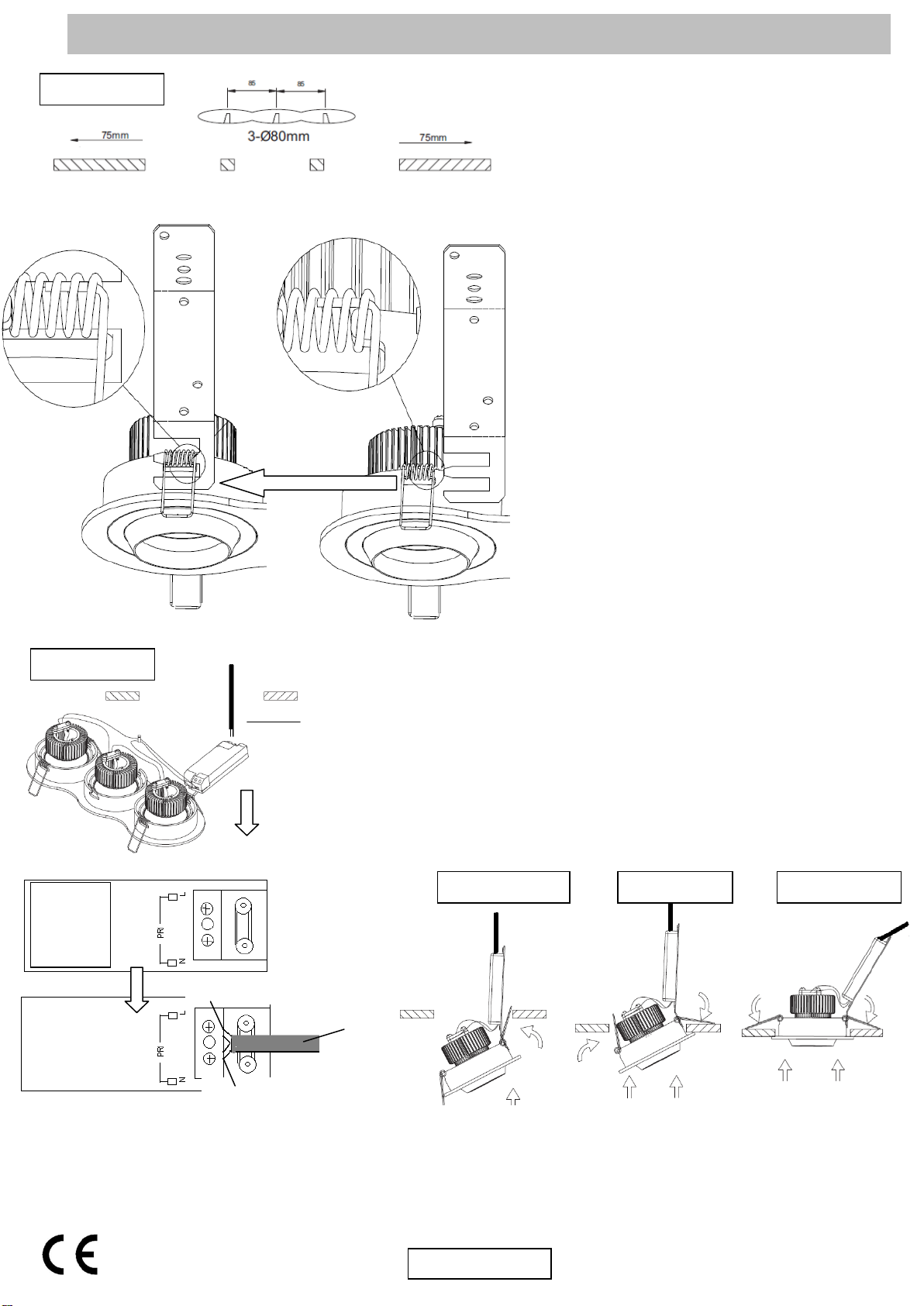
Diagram 1
1.
Diagram 1
. Cut required holes. Mark out
three points at a distance of 85mm from
each other. Use these three points as your
centres and drill 3 x 80mm diameter holes.
Make sure that there is free movement of air
around the fitting by leaving a space of at
least 75mm in all directions – including
above the fitting. Carefully fit the bracket into
the spring clips as shown.
2. Diagram 2. For ease of connection gently
pull the mains cable through the hole in the
ceiling and connect the house wiring directly
to the terminal connections situated inside
the LED supply module. NOTE: This is a
Class II fitting and must not be earthed. If you
have any earth cables make sure that they
are connected to each other – to maintain
earth continuity throughout your
property – and wrap the earth terminal
and connections in 2 layers of good
quality insulation tape and keep them
away from the terminal connections of
the fitting. To connect the incoming Live
and Neutral supply cables – firstly remove
the terminal cover at the end of the Power
Supply marked PRI - this is the end not
already pre-wired with the low voltage cable
running down to the spot heads. Connect
the supply switched Live and Neutral cables
to the terminals identified with L and N – see
detailed wiring diagram. Refit the cover
plate making sure that all basic cables are
inside the cover. If required an additional
single terminal block connector should be
used for the “loop” wires of the “Ring
Circuit”. There may be more than one set of
cables in the “loop” connections. This
additional connector must be wrapped in 2
layers of good quality insulation tape to
prevent the conductors touching the main
terminal block connections or the metal of
the fitting. If there is a “Ring Circuit” and
you do not understand the connections
you must consult an electrician.
Diagram 2
Diagram 3
Diagram 4
3. Diagrams 3 and 4.(Side View) To secure the fitting into the cut out. Ease the electrical connections into the
cut out then push the clips into the hole and then gently ease the rest of the recessed light into the hole.
5. Diagram 5. (Side View) Once in position the clips will drop down and push against the top of the ceiling and
hold the recessed fitting in place.
6. Re-connect the power supply and turn on to test.
Mains cable
Diagram 5
Pre-wired
with LV
cable –
do not
disturb.
Mains in side
Mains in cable
Other Endon Lighting Equipment manuals


