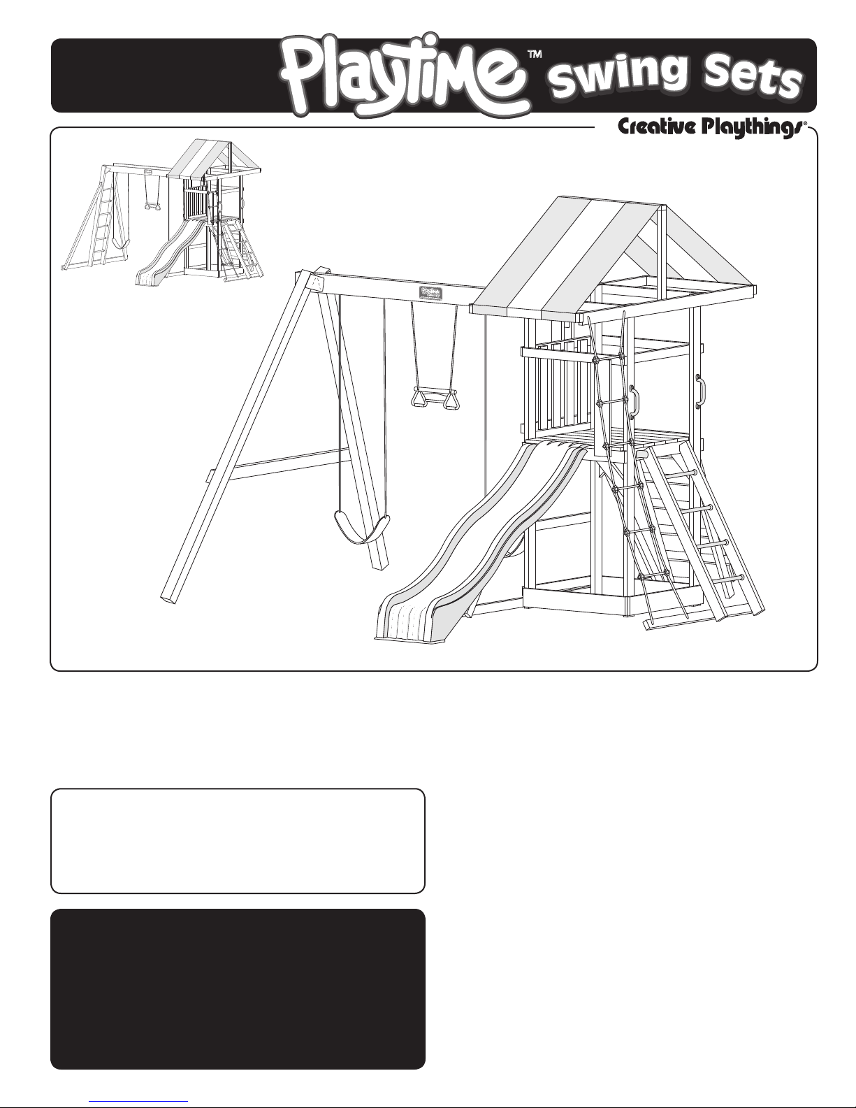
Creative Playthings Playtime PS10FRA User manual

MODEL PS10FRA
ASSEMBLY MANUAL
If you have problems or questions about your Creative Playthings Playset,
DO NOT CALL THE RETAILER.
Contact Creative Playthings Customer Service at 1-800-833-4001 or
Please read the owner’s manual before assem-
bling your Playset, it provides additional
information on the care and use of your
Playset.
You must carefully read the entire instruction
manual before proceeding with the assembly
or use of your new Playset.
Creative Playthings takes great care to de-
sign its products with your child’s safety in
mind. However, only with careful supervi-
sion and proper safety instructions, can you
be assured of safe play time on any product
designed for children.
By
This product is intended for single
family home/residential use only and
not intended for use in any public
setting. Placement in any public
setting constitutes a misuse of this
product.
All hardware on this set is specially coated
for corrosion resistance.
If non-Creative Playthings hardware is used,
it must be galvanized or stainless steel.
Model PS10FRA with
Swing Beam
Model PS10FRA with
Top Ladder
™

Assembly
© Copyright 2010, Creative Playthings. Printed in U.S.A.
MODEL PS10FRA
19766-100 Rev B (05-10) Page 2
PLAYSET SAFETY
Observing the following statements & warnings reduces the likelihood of serious or fatal injury:
&KLOGUHQVKRXOGXVHHTXLSPHQWRQO\LQLWVLQWHQGHGPDQQHU
&KLOGUHQVKRXOGQRWZHDUORRVHRUVWULQJHGFORWKLQJZKLOHXVLQJSOD\JURXQGHTXLSPHQW
&KLOGUHQVKRXOGQRWSOD\RQHTXLSPHQWLQZHWZHDWKHUFRQGLWLRQVGXHWRSRWHQWLDOO\VOLSSHU\VXUIDFHV
&KLOGUHQVKRXOG127ZDONWRRFORVHO\LQIURQWRIEHKLQGRUEHWZHHQPRYLQJVZLQJVDQGWUDSH]HV
&KLOGUHQVKRXOG127VZLQJHPSW\VZLQJVHDWV
&KLOGUHQVKRXOG127MXPSRIIVZLQJVDQGRUWUDSH]HZKLOHWKH\DUHLQPRWLRQ
Children should NOT twist swing ropes because this will weaken and reduce the strength of the rope and rope clamps.
&KLOGUHQVKRXOGVLWLQWKHFHQWHURIWKHVZLQJVZLWKWKHLUIXOOZHLJKWRQWKHVHDWV
Hanging accessories MUST be removed prior to using overhead monkey bars.
Do not allow children under age 7 to use monkey bars unless supported by an adult.
&KLOGUHQVKRXOG127EHRQWKHWRSVXUIDFHRIWKHWRSODGGHU
2QVLWHDGXOWVXSHUYLVLRQLVUHTXLUHGDWDOOWLPHVIRUFKLOGUHQRIDOODJHV
8QWLODVVHPEO\LVFRPSOHWH'2127OHW\RXUFKLOGUHQXVHWKH3OD\VHW
1HYHUIDVWHQDQ\WKLQJQRWDSSURYHGE\&UHDWLYH3OD\WKLQJVWR\RXU3OD\VHW$FFHVVRULHVRULWHPVQRWDSSURYHG
by Creative Playthings include; Dog runs, clothes lines, electrical devices, or bird feeders etc.
6XVSHQGHGURSHVFKDLQVDQGFDEOHVPXVWEHVHFXUHGDWERWKHQGV
6XVSHQGHGURSHVFKDLQVDQGFDEOHVPXVWQRWEHFDSDEOHRIORRSLQJEDFNRQWKHPVHOYHV
'RQRWDOORZPRUHWKDQOEVRQ6LQJOHRFFXSDQF\VZLQJDFFHVVRULHVVXFKDVWKH6OLQJ6ZLQJDQG7UDSH]H
'R127DOORZPRUHWKDQOEVRQPXOWLSOHXVHVZLQJDFFHVVRULHVVXFKDVWKH%DFNWR%DFN3ODVWLF+RUVH
and Wooden Lawn Swing Glider.
'R127DOORZPRUHFKLOGUHQRQWKH3OD\VHWWKDQFDQVLPXOWDQHRXVO\XVHDOOWKHVZLQJVWDWLRQVDWRQHWLPH
&KLOGUHQVKRXOG1(9(5ZHDUELF\FOHKHOPHWVZKLOHSOD\LQJRQWKHSOD\VHW
Assembly Safety:
$GXOWDVVHPEO\UHTXLUHG
)DFHVOLGHDZD\IURPWKHVXQ
.HHSWKHZRUNDUHDFOHDQDQGFOHDURIREVWUXFWLRQV
&KLOGUHQVKRXOGVWD\RXWRIWKHZRUNDUHDXQWLOWKHVDIHSOD\DUHDLVFOHDUHGRIREVWDFOHVWKH3OD\VHWKDVEHHQ
completely assembled, all hardware has been tightened and checked, and all tools have been picked up.
.HHSFKLOGUHQRIIWKH3OD\VHWXQWLOLWKDVEHHQFRPSOHWHO\DVVHPEOHG
6RPHSDUWVRIWKHDVVHPEO\SURFHVVPD\UHTXLUHKHOSIURPDQRWKHUFRPSHWHQWDGXOW
'RQRWVWDQGRQWKHSODWIRUPXQWLOWKH3OD\VHWKDVEHHQFRPSOHWHO\DVVHPEOHGXVHDVWHSODGGHULI\RXFDQ
not reach high enough.
)ROORZWKHPDQXIDFWXUHUVVDIHW\UHFRPPHQGDWLRQVIRUWKHWRROVDQGHTXLSPHQW\RXXVH
$YRLGDVVHPEOLQJ\RXU3OD\VHWLQSRRUZHDWKHUFRQGLWLRQV
:HDUSURSHUFORWKLQJDQGVDIHW\HTXLSPHQWVDIHW\JODVVHVERRWVDQGJORYHVZKLOHDVVHPEOLQJ\RXU3OD\VHW
)256$)(7<6$.(3/($6(7$.(7,0(725($'$//,16758&7,216&203/(7(/<$1'
CAUTION YOUR CHILDREN APPROPRIATELY.

Assembly
MODEL PS10FRA
19766-100 Rev B (05-10)
© Copyright 2010, Creative Playthings. Printed in U.S.A. Page 3
SAFE PLAY AREA
SELECTING THE CORRECT LOCATION FOR YOUR PLAY PRODUCT IS IMPORTANT FOR
<285&+,/'5(1ҋ66$)(7<$1'7+(352'8&7ҋ6/21*(9,7<
Playset Dimensions:
7KH02'(/36)5$3OD\VHWKDVJURXQGGLPHQVLRQVRI[
7KH02'(/36)5$3OD\VHWUHTXLUHVDOHYHOJURXQGVXUIDFHRI[IRUD6DIH3OD\$UHD
$GGLWLRQDODFFHVVRULHVPD\LQFUHDVHWKHVL]HRIWKH6DIH3OD\$UHD
7KHPD[LPXPIDOOKHLJKWIRU\RXU02'(/36)5$LVDVPHDVXUHGIURPWKHWRSRIWKH7RS/DGGHURU%HDP
Safe Play Area:
7KH6DIH3OD\$UHDUHIHUVWRD]RQHH[WHQGLQJPHWHUVEH\RQGWKH3OD\VHWRQDOOVLGHVLQFOXGLQJWKHVOLGH
and the space above the Playset. Because children may deliberately jump from a moving swing, the Safe Play
$UHDPXVWEHH[WHQGHGWRPHWHUVLQIURQWRIDQGEHKLQGDVZLQJLQJ$FFHVVRU\
7KHJURXQGVXUIDFHPXVWEHOHYHO,QVWDOOLQJ\RXU3OD\VHWRQVORSLQJJURXQGFDQFDXVHLWWROHDQRU´UDFNµ7KLV
leaning puts additional stress on all connections and joints and in time will cause those connections to loosen
and fail.
7KH6DIH3OD\$UHDPXVWEHIUHHRIDOOVWUXFWXUHVODQGVFDSLQJWUHHVDQGEUDQFKHVURFNVZLUHVDQGRWKHU
obstacles to safe play. Children can be seriously injured running, or swinging into these obstacles.
5HPRYHDOOWULSSLQJKD]DUGVIURPWKH6DIH3OD\$UHD7ULSSLQJKD]DUGVLQFOXGHURRWVVWXPSVURFNVODQGVFDS-
ing, sprinkler heads, railroad ties, plumbing and electrical connections.
'RQRWLQVWDOO\RXU3OD\VHWRYHUFRQFUHWHJUDYHODVSKDOWSDFNHGHDUWKRUDQ\RWKHUKDUGVXUIDFH7KHIROORZ-
ing is a list of recommended ground covers from the Consumer Product Safety Commission.
RECOMMENDED GROUND COVER
Suggested Material Uncompressed Depth
Double Shredded Bark Mulch 9"
Uniform Wood Chips 12"
Fine Gravel 12"
Fine Sand 12"
$Q\HGJLQJXVHGWRFRQWDLQWKHJURXQGFRYHUPXVWEHEH\RQGWKH6DIH3OD\$UHDLH/DQGVFDSH7LPEHUV
A FALL ONTO A HARD SURFACE COULD RESULT IN SERIOUS
INJURY.
Safe play area using
recommended ground cover.
Whichever is greater
Landscape Timbers 6' from
play structure.
6'
(2 M)
6'
(2 M)
6'
(2 M)
6'
(2 M)
14'
(4.27 M)
14'
(4.27 M)

Assembly
© Copyright 2010, Creative Playthings. Printed in U.S.A.
MODEL PS10FRA
19766-100 Rev B (05-10) Page 4
HARDWARE BAG CONTENTS
ASSEMBLY HARDWARE: (DRAWINGS NOT TO SCALE - ILLUSTRATIONS ARE REPRESENTATIVE OF HARDWARE)
We have packaged more hardware than is required for assembly.
+H[%ROW
Lag Screw
Truss Head Bolt
Screw
Self-Drilling Screw
Lock Washer Flat Washer
Round Head Screw
Weld Nut
Access Ladder
Bracket
:DVKHU%DJ
100 12002-205 Flat Washer 1/4"
76 12017-205 Lock Washer 1/4"
:HOG1XW%DJ
78 17001-104 Weld Nut 1/4"
%ROW%DJ
6 17003-809 Hex Bolt 1/4 x 2"
48 17003-1009 Hex Bolt 1/4 x 2-1/2"
4 17003-1609 Hex Bolt 1/4 x 4"
18 17003-1809 Hex Bolt 1/4 x 4-1/2"
2 17119-409 Truss Head Bolt 1/4 x 1"
6FUHZ%DJ
63 17020-105 Screw #10 x 1-1/2"
6FUHZ%DJ
34 17020-107 Screw #10 x 2"
4 17020-110 Screw #10 x 3"
8 17020-109 Screw #8 x 2-1/2"
8 17019-304 Round Head Screw #10x3/4"
8 17120-902 Self-Drilling Screw #10 x 2-1/2"
/DJ6FUHZ%DJ
8 17036-601 Lag Screw 1/4 x 1-1/2"
4 17036-1201 Lag Screw 1/4 x 3"
4 17036-1601 Lag Screw 1/4 x 4"
5RFN+DUGZDUH3DFN
10 12002-203 Flat Washer 8mm
10 12017-205 Lock Washer 1/4"
10 17001-104 Weld Nut 1/4"
10 17003-409 Hex Bolt 1/4 x 1"
+DUGZDUH%DJ$FF%UDFNHW
4 12002-206 Flat Washer 5/16"
4 12017-206 Lock Washer 5/16"
2 14161-400 Access Ladder Bracket - Green
4 17001-105 Weld Nut 5/16"
2 17003-411 Hex Bolt 5/16 x 1"
4 17003-611 Hex Bolt 5/16 x 1-1/2"

Assembly
MODEL PS10FRA
19766-100 Rev B (05-10)
© Copyright 2010, Creative Playthings. Printed in U.S.A. 3DJH
PRE ASSEMBLY INFORMATION
&5($7,9(3/$<7+,1*63/$<6(7686($)(:67$1'$5'&211(&7,216
BECOMING FAMILIAR WITH THESE CONNECTIONS WILL SIMPLIFY ASSEMBLY AND
INSURE A SAFER PLAY PRODUCT FOR YOUR CHILDREN.
+H[%ROW:HOG1XW$VVHPEO\3URFHGXUH
Assembly Layout:
Align the holes in the parts to be fastened. Start
preliminary tightening of bolt into weld nut by
hand. Tighten each bolt with a wrench until the
lock Washer is fully compressed between the
KHDGRIWKHEROWDQGWKHÁDW:DVKHU
Correct Assembly:
Bolt has been screwed securely into weld nut
and the connection is tight. Check connec-
tions periodically for tightness during the life
of the Playset . Do not over tighten.
Incorrect Assembly:
During assembly or maintenance the bolt pro-
trudes 1/8" past the weld nut. Call customer
service or replace the bolt at a local hardware
store. You may be overtightening or using the
wrong size bolt.
Failure to replace this bolt with a shorter
one could result in serious injury.
Typical Installation - Lag Screws:
3LORWGULOOZLWKWKHDSSURSULDWH
diameter drill bit and then use
a socket to tighten.
'2127RYHUWLJKWHQ
Typical Installation - Wood Screws:
8VHDQHOHFWULFGULOORUVFUHZJXQWRGULYHVFUHZV
'ULOOSLORWKROHVZKHUHUHTXLUHG
:HUHFRPPHQGWKDW\RXOXEULFDWHWKH
threads of the screws with beeswax or
soap to ease installation and minimize
breaking screws.
It is very important to make cer-
tain that the tops of all screws are
ÁXVK ZLWK WKH VXUIDFH RI WKH ZRRG
and there are no protruding sharp
edges.

Assembly
© Copyright 2010, Creative Playthings. Printed in U.S.A.
MODEL PS10FRA
19766-100 Rev B (05-10) 3DJH
3/$<6(79,(:
3OD\3DFN
Steering Wheel
Telescope
A
B
ZD
E
F
G
H
IJ
L
M
N
AA
AB
AC
AG
AJ
AD
AF
AI
AK AL
AM
AN
Q
R
S2
T
V
W
X
C
&KDLQHG6ZLQJ$FFHVVRULHV
2 40321-400 Sling Swing, Green w/Chain
1 40311-402 Ring Trapeze Assembly w/Chain
5RSHG6ZLQJ$FFHVVRULHV
2 40009-400 Sling Swing, Green w/Rope
1 40381-100 Plastic Ring Trap Combo, Yellow
or
Swing Options:
60056-101 Swing Beam60055-101 Top Ladder
U

Assembly
MODEL PS10FRA
19766-100 Rev B (05-10)
© Copyright 2010, Creative Playthings. Printed in U.S.A. Page 7
&20321(179,(:
T 4 31682-102 Angle Brace 2 x 4 x 17-1/4"
U 2 32168-102 Swing Mount 2 x 4 x 17"
V 1 32169-102 Long Wall Slat 5/4 x 6 x 27-1/2"
W 2 32183-102 Sandbox End 5/4 x 6 x 35-3/4"
X 7 32184-102 Platform Board 5/4 x 6 x 33"
Y* 1 32187-102 Platform Stringer 2 x 4 x 35"
Z 1 32188-102 Sandbox Side Left 5/4 x 3 x 35"
AA 4 32191-102 Side Wall Support 2 x 3 x 35"
AB 4 32192-102 End Wall Support 2 x 3 x 35-3/4"
AC 1 32197-102 Platform End 2 x 4 x 35-3/4"
AD 1 32199-102 Right Sandbox Side 5/4 x 6 x 35"
AF 5 32207-102 Rock Board 5/4 x 6 x 23-1/2"
AG 1 32518-102 Bottom Board 5/4 x 6 x 23-1/2"
AH* 1 33182-102 Left Platform Side 2 x 4 x 35"
AI 1 33183-102 Right Platform Side 2 x 4 x 35"
AJ 1 33184-102 Platform Back 2 x 4 x 35-3/4"
AK 2 33187-102 Tent Post 2 x 3 x 27-3/4"
AL 2 33190-102 End Tent Support 2 x 3 x 39-1/4"
AM 1 33191-102 Tent Beam 2 x 3 x 35-7/8"
AN 4 33192-102 Narrow Wall Slat 5/4 x 4 x 23-1/2"
A 1 32181-102 Gym Base Rail 2 x 3 x 94"
B 1 32193-102 Bottom Rope Ladder Support 2 x 3 x 50"
C 2 32195-102 Angled Side Support 2 x 3 x 51-1/8"
D 2 32730-102 Rock Climber Upright 2 x 3 x 51-7/8"
E 2 33180-102 Right Corner Post 2 x 4 x 88-1/2"
F 2 33181-102 Left Corner Post 2 x 4 x 88-1/2"
G 1 33185-102 Left Access Ladder Rail 2 x 4 x 53-1/4"
H 1 33186-102 Right Access Ladder Rail 2 x 4 x 53-1/4"
I 1 33188-102 Long Tent Support 2 x 3 x 81-3/8"
J 1 33189-102 Tent & Rope Support 2 x 4 x 81-3/8"
K* 1 11051-2131 Assembly Block
L 4 14203-400 1" Dia. x 18" Steel Rung, Green
M 4 15034-100 Hand Grip, Yellow
N 8 15154-400 1" Rung Collar
O* 5 36515-102 Ground Stakes
P* 1 40378-100 Rock Pack (5)
Q 1 40502-100 Rope Ladder
R 1 40512-402 Franklin Tent, Green & Yellow
S1* 1 33315-102 Filler Strap 5/4 x 2 x 17"
S2 1 31765-102 Ladder Slat 5/4 x 3 x 19"
1 50459-100 Instruction Pack, Franklin
1 50459-700 Franklin Hardware Master Pack
1 50475-100 Playtime Playpack 1
1 8515-202 8 Ft Green Wave Slide
&RPSRQHQW3DUW,GHQWLÀFDWLRQ
Take inventory of all parts, making sure nothing is missing or
GHIHFWLYH,I \RX ÀQG WKDW SDUWVDUH PLVVLQJ RU GHIHFWLYH FDOO
the Creative Playthings Customer Service Department at
1-800-833-4001. * Not visible in illustration on Page 6
%2;
%2;

Assembly
© Copyright 2010, Creative Playthings. Printed in U.S.A.
MODEL PS10FRA
19766-100 Rev B (05-10) Page 8
MAINTENANCE INSTRUCTIONS
<285&5($7,9(3/$<7+,1*63/$<6(7,667$,1('$7285)$&725<
STAINING IS NOT NEEDED AT THE TIME OF INITIAL ASSEMBLY.
Re-staining Information:
3LJPHQWHGH[WHULRUZDWHUUHSHOOHQW VWDLQV DUHUHFRPPHQGHGDQGZLOOSURYLGH DQ H[FHOOHQWEDUULHUDJDLQVWPRLVWXUH
ZLWKRXWKLGLQJWKHQDWXUDOZRRGJUDLQRUOHDYLQJDÀOPWKDWPD\ODWHUFUDFNRUSHHO
:HUHFRPPHQGWKDW\RXDSSO\VWDLQDFFRUGLQJWRWKHLQVWUXFWLRQVDQGSUHFDXWLRQVUHFRPPHQGHGE\WKHVWDLQPDQXIDFWXUHU
,WVKRXOGWDNHWKUHHRUPRUHTXDUWVWRFRYHU\RXUVHW
&RQWDFW\RXUORFDOGHDOHURUFDOO&UHDWLYH3OD\WKLQJVIRURXUVWDLQLQJSURGXFWV
$OOUXQJVDUHSUHÀQLVKHGDWWKHIDFWRU\DQGGRQRWUHTXLUHDQ\ÀQLVKLQJDWWKHWLPHRILQLWLDODVVHPEO\
'RQRWSDLQWRUYDUQLVKUXQJVRUVWHSV
$YRLGXVLQJÀQLVKHVWKDWFUHDWHVOLSSHU\VXUIDFHV
Maintenance:
:RRGHQSOD\JURXQGHTXLSPHQWZLOOODVWIRU\HDUVZLWKSURSHUPDLQWHQDQFH0DLQWHQDQFHRIWKH3OD\VHWÀQLVKZLOOYDU\
depending on weather climate.
$VDVDIHW\SUHFDXWLRQFKHFNDOOKDUGZDUHVXFKDVQXWVDQGEROWVIRUWLJKWQHVVWZLFHDPRQWKGXULQJXVHDQGDWWKH
EHJLQQLQJRIHDFKSOD\VHDVRQ7LJKWHQDVUHTXLUHGDQGVSHFLÀHGLQWKHVHLQVWUXFWLRQV'RQRWRYHUWLJKWHQ
&KHFNVWUXFWXUHWZLFHPRQWKO\GXULQJXVDJHIRUDQ\HYLGHQFHRIGHWHULRUDWLRQ,IXSRQLQVSHFWLRQKDUGZDUHKDVVKDUSHGJHV
rusted or structural pieces have signs of premature failure; replace them through Creative Playthings Customer Service.
2LODOOPHWDOOLFPRYLQJSDUWVPRQWKO\GXULQJWKHXVDJHVHDVRQ
7KHVZLQJVWUDSH]HWHQWURSHODGGHUVDQGDQ\RWKHUUHPRYDEOHSODVWLFDFFHVVRULHVVKRXOGEHUHPRYHGDQGWDNHQ
indoors when outside temperatures drop below 32° F (0° C).
:RRGZLOOH[SDQGDQGFRQWUDFWDVLWDGMXVWVWRWHPSHUDWXUHFKDQJHVDQGYDU\LQJPRLVWXUHFRQGLWLRQV&KHFNVRUFUDFNV
are a natural characteristic of all wood and will not affect the strength or durability of the wooden components.
7RPDLQWDLQWKHÀQLVKRI\RXUVHWDOLJKWVDQGLQJDQGDQDSSOLFDWLRQRIDQH[WHULRUVWDLQZLOOUHSDLUVFUDWFKHVDQGSUHYHQW
wood from aging prematurely.
)LQLVKHVDSSOLHGWRODGGHUUXQJVPXVWQRWFUHDWHDVOLSSHU\VXUIDFH1HYHUYDUQLVKRUSDLQW:KHQUHÀQLVKLQJUXQJV
sand lightly and use an exterior stain or boiled linseed oil.
7KHZRRGSDUWVRI\RXU3OD\VHWVKRXOGQHYHUEHGLVSRVHGRIE\EXUQLQJ
'LVSRVHRIDOOSDUWVVRDVQRWWRFUHDWHDKD]DUG
&KHFNDOOFRYHULQJVIRUEROWVDQGVKDUSHGJHVDQGUHSODFHZKHQUHTXLUHG
&KHFNVZLQJVHDWVFKDLQVURSHVDQGRWKHUPHDQVRIRIDWWDFKPHQWVIRUHYLGHQFHRIGHWHULRUDWLRQ5HSODFHWKURXJK
Creative Playthings Customer Service.
Tools & Materials Suggested for Finishing & Assembly:
&ODZ+DPPHU
&DUSHQWHUҋV/HYHO
%R[:UHQFKRU6RFNHWV
(OHFWULF'ULOO
DQG'ULOO%LWV+LJK6SHHG
6FUHZGULYHURUGULYHUGULOO0HGLXP3KLOOLSV
/RFNLQJ3OLHUV
IW7DSH0HDVXUH
)UDPLQJ6TXDUH
IW6WHS/DGGHU
%HHVZD[RU6RDS8VHGWROXEULFDWHVFUHZWKUHDGV

Assembly
MODEL PS10FRA
19766-100 Rev B (05-10)
© Copyright 2010, Creative Playthings. Printed in U.S.A. 3DJH
ASSEMBLY INSTRUCTIONS
STEP 1 – Base Components:
Identify and separate all wood components, hardware, and
fasteners.
Identify and layout base components shown in the illustra-
tion at right.
STEP 2 – Corner Posts:
Fasten one Sandbox End (W) to one Left Corner Post (F)
using one 1/4" x 4" Hex Bolt Assembly. $+H[%ROW$VVHP-
EO\FRQVLVWVRIRQH+H[%ROWRQH/RFN:DVKHURQH)ODW
Washer and one Weld Nut.
Stand the assembly up and fasten the Gym Base Rail (A)
using a 1/4" x 2-1/2" Hex Bolt Assembly.
Note the Location of the pre-drilled holes in the Corner Post
and the Sandbox End in the illustration at right.
(Orient all Corner Posts so the hole 36" from the bottom is
offset toward the Sandbox Ends.)
1RWH$+H[%ROW$VVHPEO\FRQVLVWVRIRQH+H[%ROWRQH
Lock Washer, one Flat Washer and one Weld Nut.
STEP 3 – Base Assembly:
Fasten one Sandbox End (W) to the other Left Corner Post
(F) using one 1/4" x 4" Hex Bolt Assembly.
Stand the components up and fasten to the assembly from
step 2, using a 1/4" x 2-1/2" Hex Bolt Assembly.
F
W
A
A
W
W
F
A
W
AD

Assembly
© Copyright 2010, Creative Playthings. Printed in U.S.A.
MODEL PS10FRA
19766-100 Rev B (05-10) Page 10
ASSEMBLY INSTRUCTIONS
STEP 4 – Base Assembly:
Fasten the Right Sandbox Side (AD) to the two Right Corner
Posts (E) using four 1/4" x 2" Hex Bolt Assemblies.
Position the two Corner Posts vertically and fasten to the
assembly from step 3 using two 1/4" x 4" Hex Bolt Assem-
blies.
67(3²6DIHW\5DLO
Fasten one Side Wall Support (AA) to the left Corner Posts
as a safety rail. Use four 1/4" x 2-1/2" Hex Bolt Assemblies.
Move the base assembly into position in your “Safe Play
Area". Do not forget to account for the Access Ladder, Slide,
and Swing Beam or Top Ladder.
1RWH5HIHUWRSDJHIRUWKH6DIH3OD\$UHDGLPHQVLRQV
67(3²3ODWIRUP6LGHV
Fasten the Left Platform Side (AH) to the inside of the Left
Corner Posts using the holes 44-1/2" from the bottom with
Four 1/4" x 2-1/2" Hex Bolt Assemblies.
Repeat with the Right Platform Side (AI) on the inside of the
Right Corner Posts.
E
E
AI
AH
AD
AA

Assembly
MODEL PS10FRA
19766-100 Rev B (05-10)
© Copyright 2010, Creative Playthings. Printed in U.S.A. Page 11
ASSEMBLY INSTRUCTIONS
STEP 7 – Platform Ends:
Fasten the Platform End (AC) to the front Corner Posts us-
ing one 1/4" x 4-1/2" Hex Bolt Assembly in each end.
Fasten the Platform Back (AJ) to the back Corner Posts in
the same way.
.STEP 8 – Platform Stringer:
Fasten the Platform Stringer (Y) between the Platform Ends
using one 1/4" x 4" Lag Screw and 1/4" Washer in each
end.
67(3²$QJOH%UDFHV
Loosely fasten the bottom of the four Angle Braces (T) to
the Corner Posts using 1/4" x 2-1/2" Hex Bolt Assemblies.
Loosely attach the top of the Angle Braces to the Platform
End or Platform Back using 1/4" x 2-1/2" Hex Bolt Assem-
blies.
Y
T
T
AJ
AC

Assembly
© Copyright 2010, Creative Playthings. Printed in U.S.A.
MODEL PS10FRA
19766-100 Rev B (05-10) Page 12
ASSEMBLY INSTRUCTIONS
STEP 10 – Side Supports:
Fasten the bottom of each Angled Side Support (C) to the
Gym Base Rail using two 1/4" x 2-1/2" Hex Bolt Assemblies.
/HDYHÀQJHUWLJKW6ZLQJWKH$QJOHG6LGH6XSSRUWVDJDLQVW
the Left Corner Posts as shown. Using a level check that the
Corner Posts are plumb. Mark the position that the upper
hole in the Side Support meets the Corner Posts. Use a 1/8"
drill to make a 2-1/2" deep pilot hole in each Corner Post.
Attach the Side Supports to the Corner Posts using 1/4 x 4"
Lag Screws and 1/4" Flat Washers.
STEP 11 – Square and Secure Gym:
Use a level and square to check that the Corner Posts are
plumb and the Side and End Supports are level. Once the
position is satisfactory, tighten the bolts holding the Angled
Side Supports to the Gym Base Rail and the Angle Braces
to the Corner Posts. Check Gym position again and then
tighten the bolts that connect the Angle Braces to the Plat-
form Ends.
)LQDOO\ ÀQLVK VHFXULQJ WKH 6DQGER[ (QGV WR WKH &RUQHU
Posts using #10 x 2" Flat Head Wood Screws in the holes
provided.
STEP 12 – Platform Boards:
3ODFHRQH3ODWIRUP%RDUG;ÁXVKWRWKHHGJHRIHDFK3ODW-
IRUP(QGDVVKRZQ(YHQO\VSDFHWKHÀYHUHPDLQLQJ3ODW-
IRUP%RDUGVEHWZHHQWKHÀUVWWZR3ODWIRUP%RDUGV)DVWHQ
HDFKWRWKHSODWIRUPIUDPHXVLQJÀYH[)ODW+HDG
Wood Screws.
X
1
4
C
C
3
2
Drill Pilot Hole

Assembly
MODEL PS10FRA
19766-100 Rev B (05-10)
© Copyright 2010, Creative Playthings. Printed in U.S.A. Page 13
ASSEMBLY INSTRUCTIONS
STEP 13 – End Wall Supports:
Fasten two End Wall Supports (AB) to the front Corner Posts
and two to the rear Corner Posts as shown. Use two 1/4" x
4-1/2" Hex Bolt Assemblies in each End Wall Support.
STEP 14 – Side Wall Support:
Fasten two Side Wall Supports (AA) to the outside of the Left
Corner Posts in the positions shown at right. Use four 1/4" x
2-1/2" Hex Bolt Assemblies in each Side Wall Support.
Use four 1/4" x 2-1/2" Hex Bolt Assemblies to fasten one
Side Wall Support on the inside of the Right Corner Posts
as shown.
67(3²/RQJ7HQW6XSSRUWV
Fasten the Long Tent Support (I) to the Left Corner Posts us-
ing four 1/4" x 2-1/2" Hex Bolt Assemblies as shown.
Fasten the Tent & Rope Support (J) to the Right Corner Posts
using four 1/4" x 2-1/2" Hex Bolt Assemblies as shown.
AA
AA
AB
AB
IJ

Assembly
© Copyright 2010, Creative Playthings. Printed in U.S.A.
MODEL PS10FRA
19766-100 Rev B (05-10) Page 14
ASSEMBLY INSTRUCTIONS
67(3²(QG7HQW6XSSRUW
Fasten an End Tent Support (AL) to each end of the Long
Tent Support and Tent & Rope Support using four 1/4 x 3"
Lag Screws with four 1/4" Flat Washers as shown.
STEP 17 – Tent Posts:
Fasten the Tent Posts (AK) to the Long Tent Support and
Tent & Rope Support as shown. Use two 1/4" x 2-1/2" Hex
Bolt Assemblies for each Tent Post. Use a level to ensure
that the Tent Posts are plumb.
STEP 18 – Tent Beam:
Fasten the Tent Beam (AM) to the Tent Posts as shown. Use
two #10 x 3" Screws at each end.
AL
AK
AM

Assembly
MODEL PS10FRA
19766-100 Rev B (05-10)
© Copyright 2010, Creative Playthings. Printed in U.S.A. 3DJH
ASSEMBLY INSTRUCTIONS
67(3²$VVHPEOH$FFHVV/DGGHU
Slide a Rung Collar (N) over each end of all 18" Rungs (L).
Press each 18" Rung Assembly into the holes in the Right
Access Ladder Rail (H) until the Rung Collar is tight against
the Rail. Position the other Left Access Ladder Rail (G) so
WKH5XQJ$VVHPEOLHVÀWLQWRWKHKROHV,IWKHÀWLVWRRWLJKWWR
assemble by hand, use a hammer, padded with the Assem-
bly Block (K), to force the Rails onto the Rung Assemblies.
Use one #10 x 2-1/2" Self-drilling Screw to secure each end
of each Rung. Make sure that the collar of each Rung As-
sembly is tight against the Rails before inserting the screws
LQWRWKHKROHVDQGIDVWHQLQJWKHPZLWKDGULOOÀWWHGZLWKD
Phillips bit.
:KHQIDVWHQLQJSUHVVÀUPO\ZLWK\RXUERG\PDVVFHQWHUHG
over the drill.
STEP 20 – Bottom Rope Support and Slat:
Fasten the Bottom Rope Ladder Support (B) to the Access
Ladder Assembly using two 1/4" x 4-1/2" Hex Bolt Assem-
blies as shown.
Fasten the Ladder Slat (S1) to the Access Ladder Rails us-
ing four #10 x 1-1/2" Screws. The gap between the Ladder
Slat and the top Rung should be 3-1/4".
STEP 21 – Fasten Access Ladder to Gym:
Loosely fasten two Access Ladder Brackets to the Access
Ladder Rails using one 5/16" x 1-1/2" Hex Bolt Assembly
each, as shown.
Position the Access Ladder Assembly against the Right Plat-
form Side.
Fasten the Access Ladder Brackets to the Right Platform
Side using 5/16 x 1-1/2" Hex Bolt Assemblies, as shown.
Tighten all hardware.
G
N
L
K
H
S1 B
3-1/4"

Assembly
© Copyright 2010, Creative Playthings. Printed in U.S.A.
MODEL PS10FRA
19766-100 Rev B (05-10) 3DJH
ASSEMBLY INSTRUCTIONS
67(3²/HIW6DQGER[6LGH
Fasten the Left Sandbox Side (Z) to the Left Corner Posts
with two 1/4" x 2" Hex Bolt Assemblies as shown. The Sand-
box Side rests on the Gym Base Rail.
STEP 23 – Rock Uprights and Ground Stake:
Loosely fasten the Access Ladder Brackets to the outside of
the Rock Climber Uprights (D) using one 5/16" x 1-1/2" Hex
Bolt Assembly each, as shown. Fasten each Access Bracket
to the gym using one 5/16 x 1-1/2" Hex Bolt Assembly.
Make sure that the Rock Climber Uprights are parallel to
each other and perpendicular to the gym. The lower corners
of the Uprights should be set into the play surface. Drive one
Ground Stake (O) into the ground along side a Rock Climber
Upright, as shown. The upper corner of the Stake should be
behind the top edge of the Upright to avoid interfering with
the Bottom Board in the next step.
Secure the stake with two #8 x 2-1/2" Wood Screws through
the pre-drilled hole.
Do not use concrete to set Ground Stakes. Pound a metal spike or
rod into the ground to start a hole in hard or rocky ground.
STEP 24 – Rock Boards:
/RFDWH WKH %RWWRP %RDUG $* DQG ÀYH 5RFN %RDUGV $)
Align the top of a Rock Board with the top of the Rock Up-
rights. Fasten the Rock Board using four #10 x 2" Wood
Screws. Continue the Rock Wall assembly by attaching Rock
Boards every 3-1/4". Alternate the position of the holes in the
Rock Boards as shown in the illustration. Finish by with the
Bottom Board in the lowest position.
1RWH'ULOODGLDPHWHUSLORWKROHLQWKH5RFN&OLPEHU8S-
rights for each #10 x 2" Wood Screw.
Z
O
AF
AF
AG
AF
D
3-1/4"

Assembly
MODEL PS10FRA
19766-100 Rev B (05-10)
© Copyright 2010, Creative Playthings. Printed in U.S.A. Page 17
ASSEMBLY INSTRUCTIONS
67(3²5RFNV
Fasten the Climbing Rocks to all the holes in the Rock Boards
using two 1/4 x 1" (or 1-1/2") Hex Bolts, 1/4" Lock Washers,
8 MM Flat Washers and 1/4" Weld Nuts for each Rock. The
bolt must seat completely into the Climbing Rocks, and not
protrude more than a 1/8" past the end of the Weld Nut.
Protruding bolts can be a hazard to users, replace any pro-
truding Bolts.
This gym may come equipped with either 1/4 x 1" or 1/4 x
1-1/2" Hex Bolts for this step.
67(3²+DQG*ULSV
3ODFHRQH+DQG*ULSÁDWDJDLQVWWKHEDFNIDFHRIWKHEDFN
Left Corner Post as shown. The bottom hole of the Hand
Grip should be approximately 8" above the top of the Plat-
form surface.
With the Hand Grip centered on the face of the Corner Post,
mark the positions of the holes in the Hand Grip. Drill 1/8"
diameter pilot holes 1" deep at the marks. Fasten the Hand
Grip using two 1/4" x 1-1/2" Lag Screws and two 1/4" Flat
Washers.
Repeat, mounting a Grip in each of the positions shown.
P
STEP 27 – Long Wall Slat:
Position the Long Wall Slat (V) on the front of the Gym 2-1/2"
from the front Right Corner Post. Fasten the Long Wall Slat
to the Platform End and the End Wall Support with #10 x
1-1/2" Flat Head Wood Screws. The top of the Slat should
be approximately 1" below the top edge of the End Wall Sup-
port.
M
8"
2-1/2".
M
V

Assembly
© Copyright 2010, Creative Playthings. Printed in U.S.A.
MODEL PS10FRA
19766-100 Rev B (05-10) Page 18
ASSEMBLY INSTRUCTIONS
67(3²)LOOHU6WUDSV7RS/DGGHU2QO\
When the Swing Mounts are in the position required to mount
a Top Ladder, the space between the Swing Mounts and the
Left Corner Posts becomes a potential head entrapment.
Center the Filler Straps (S2) in the space between each
6ZLQJ0RXQWDQGWKHDGMDFHQW/HIW&RUQHU3RVW)DVWHQXV-
ing two #10 x 1-1/2" Screws each.
Do NOT install the Filler Straps on a gym with a Swing
Beam.
U
U
Top Ladder or Swing Beam
Swing Beam
Top Ladder
1-1/2"
1-1/2"
C
L
C
L
8-1/4"8-1/4"
Your gym comes with either a Swing Beam or Top
Ladder. Both come with instructions for assem-
bly and mounting. The instructions on this page
show the unique steps for mounting them to this
gym.
STEP 28 — Swing Mounts:
The Swing Mounts (U) for this gym fasten in a way very simi-
lar to the method shown in the instructions included with the
Swing Beam or Top Ladder that comes with this gym. Follow
those instructions for drilling 5/16" holes in the Wall Supports.
Fasten the Swing Mounts in the appropriate positions using
two 1/4 x 4-1/2" Hex Bolt Assemblies each. Mount the Swing
Beam or Top Ladder as shown in the instructions provided.
S2
S2

Assembly
MODEL PS10FRA
19766-100 Rev B (05-10)
© Copyright 2010, Creative Playthings. Printed in U.S.A. 3DJH
ASSEMBLY INSTRUCTIONS
3" Typical Gap AN
R
Q
STEP 30 – Narrow Wall Slats:
Place the four Narrow Wall Slats (AN) against the inside of
the left Side Wall Supports as shown. Space them evenly
across the opening and fasten them with four #10 x 1-1/2"
Flat Head Wood Screws each. The upper edge of the Wall
Slats should be approximately 3/8" below the top of the up-
per End Wall Support. The position Narrow Wall Slats can be
DGMXVWHGWRPLVVWKH6ZLQJ0RXQWKDUGZDUHMXVWPDNHVXUH
that there is no gap wider than 3-1/2" and smaller than 9".
Special addendum for Top Ladder: The opening between
the Top Ladder Rails should be closed off using two Wall
Slats, unless the Top Ladder is to be used as Monkey Bars.
If this space is left open, the swings should be removed to
SUHYHQWDFRQÁLFWRISOD\
STEP 31 – Tent:
Drape the Tent (R) across the top of the gym, over the Tent
Beam. Secure the Tent to the end of the front End Tent Sup-
port using three #10x 3/4" Round Head Screws* through the
grommets in the hem of the Tent. If the heads of the Screws
are smaller than the grommet openings, use 1/4" Flat Wash-
ers under the heads of the Screws.
Stretch the Tent smoothly and evenly across the Tent Beam.
Secure the other end of the Tent to the rear End Tent Sup-
port in the same manner.
* Flat headed screws may be provided in place of the round
head screws.
STEP 32 – Rope Ladder:
Push one side of the Rope Ladder Assembly (Q) through a
hole in the Tent & Rope Support leaving 6" of rope sticking
RXWSDVW WKH6XSSRUW7LHD ÀJXUHHLJKWNQRWLQ WKHURSHWR
prevent it from slipping out through the hole. Tie the other
URSHHYHQZLWKWKHÀUVWURSH7KHUHPXVWEHDWOHDVWEH-
tween the bottom of the Tent & Rope Support and the top
horizontal rope of the Rope Ladder.
At the bottom, pull the rope through the holes in the Bottom
Rope Ladder Support until the rope is tight. Tie the bottom
end of the Rope Ladder; leave no slack in the rope.
Figure 8
Knot
9"

Assembly
© Copyright 2010, Creative Playthings. Printed in U.S.A.
MODEL PS10FRA
19766-100 Rev B (05-10) Page 20
ASSEMBLY INSTRUCTIONS
Save all instruction sheets and receipts in case it becomes necessary to contact Creative Playthings
for warranty service and/or part replacement. The warranty can be found in your Owner’s Manual.
3OHDVHÀOORXWWKHZDUUDQW\FDUGRQWKHEDFNRI\RXURZQHUVPDQXDO<RXUFRPSOHWHGZDUUDQW\FDUG
will allow us to quickly process warranty claims.
Thank you.
STEP 34 – Ground Stakes:
Hammer two Ground Stakes (O) into the ground at the ends
of the Gym Base Rail. Place the Ground Stakes 6" to 9" from
each end and approximately 1/4" below the top edge of the
Base Rail. Hammer another Ground Stake next to the front
Access Ladder Rail as shown. Fasten each Ground Stake
using two #8 x 2-1/2" Screws through the pre-drilled holes.
Pound the last Ground Stake along the inside of the Front
Sandbox End, on the side farthest from the Gym Base Rail.
Secure the Stake with two #10 x 2" Screws.
1RWH'R127XVHFRQFUHWHWRVHW*URXQG6WDNHV6LPSO\
pound them in to the ground. Use a metal spike or rod to
start a hole in hard or rocky ground.
STEP 33 – Slide:
Center the Slide between the front Left Corner Post and
the Long Wall Slat. Pull it tight to the platform until it stops
against the front edge of the Platform End. Check that the
Slide extends out perpendicular from the play set.
Using the holes in the slide for guides, drill 5/16" holes
through the platform and secure slide using two 1/4" x 1"
bolts from the top and two weld nuts from below.
67(3²+DQJ6ZLQJV
Hang the Swings and Ring Trapeze as shown in the illustra-
tions.
7KHKHLJKWRIWKH6ZLQJVLVDGMXVWHGE\XVLQJDGLIIHUHQWOLQN
in the chain.
O
O
Table of contents
Other Creative Playthings Swing Set manuals
Popular Swing Set manuals by other brands

Backyard Discovery
Backyard Discovery EAGLES NEST ELITE manual

Graco
Graco ISPS040AC owner's manual

new plast
new plast AG200 10250DX Assembling instructions

Huck
Huck Douglas Fir Assembly instructions

XDP Recreation
XDP Recreation 74520SF manual

Backyard
Backyard LITTLE BRUTUS 2051171 Owner's manual & assembly instructions

Outsunny
Outsunny 344-025 Assembly instruction

Fit N'Fun
Fit N'Fun MA3201 Owner's manual and assembly instructions

Palmako
Palmako MV70-3121-2 Assembly, installation and maintenance instructions

Graco
Graco ISPS031AA owner's manual

Backyard Discovery
Backyard Discovery Oxford 6111 owner's manual

e. Beckmann
e. Beckmann 203331 Assembly instructions