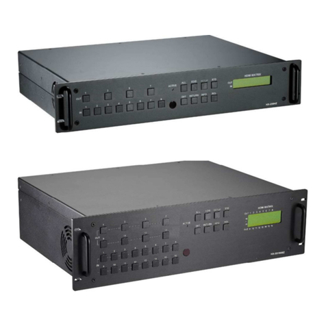
Creator Electronics DVI Matrix Switcher User manual

CREATOR Electronics
DVI MatrixSwitcher
DVI Matrix Switcher
User Manual
DVI Matrix Switcher
AVersion CR-DVI0808-A-01
2006 July
Please read this manual carefullybeforeusing thisproduct

Notes
ThisDVI MatrixSwitchers User Manualtakesexample ofthe Matrix model
DVI0808-A. Itcanbe used asuser smanual ofother RGB matrixswitcher
models.
Thismanual is onlyan instruction foroperators,not for anymaintenanceusage.
Anychanges offunctionsand parameters since then will beinformed separately.
Pleaserefer to the dealers forthe latest details.
Thismanual is copyrightCREATORCorporation (China).All rightsreserved. No
part ofthispublication maybe copied orreproduced without the priorwritten
consentofCREATOR Corporation (China).
All product function is valid till 2006-6-30

DVI Matrixswitcher usermanualCR-DVI0808-A-01 CREATOR
ii
!
SafetyO
p
erationGuide
In orderto guaranteethe reliableoperation of the equipmentsand safetyofthe staff please
abide bythe following proceeding in installation,using and maintenance:
The system must be earthedproperly.Please donotusetwobladesplugs and ensurethealternating
power supply ranged from100v to 240v and from50Hzto 60Hz.
⑵
Donot put the switcher in a placeof toohot or too cold.
⑶
As the powergenerating heatwhenrunning,the working environment should be maintained
fine ventilation,in case ofdamagecaused byoverheat.
⑷
Please cut offthe general powerswitch in humid weather or left unused forlong time.
⑸
Beforefollowing operation, ensure that the alternating currentwireispull outofthe power
supply:
A.Takeoff orreship anycomponentsofthe equipment.
B.Takeoff orrejoin anypin or other linkofthe equipment.
⑹
As to non-professional or without permission,please DONOT trytoopenthe casing ofthe
equipment,DONOT repairiton your own, incase of accidentorincreasingthe damageofthe
equipment.
⑺
DO NOT splash anychemistrysubstance or liquid in the equipment or around.

DVI Matrixswitcher usermanualCR-DVI0808-A-01 CREATOR
iii
Contents
1. Introduction.........................................................................................................................1
1.1 About DVI Matrix SwitcherSystem.............................................................................................1
1.2 DVIMatrixSwitcherModels........................................................................................................1
2. DVI Packing of the Product..............................................................................................2
3. DVI Installation....................................................................................................................2
4. Front Viewand Rear View of the Product .....................................................................3
4.1 Front viewofDVI0808-A...............................................................................................................3
4.2 RearviewofDVI0808-A................................................................................................................3
5. External Connection..........................................................................................................3
5.1 Introduction ofthe Input and Output Connectors......................................................................3
5.2 Connection ofRS-232 Communication Port................................................................................4
5.2.1 Connection with Control System.........................................................................................................4
5.2.2 Connection with Computer...................................................................................................................4
5.2.3 Using Of Ethernet Adapter ...................................................................................................................4
5.3 How to Connectwith theInputand Output Terminals..............................................................7
6. Operation of the ControlPanel......................................................................................11
6.1 Front PanelDescription................................................................................................................11
6.2 Command Format of the Switching Operation.........................................................................12
6.3 Examples of Operation.................................................................................................................13
7. Usage of the RemoteController(OptionalAccessory) .........................................14
8. Operation of the SwitcherApplication.........................................................................15
8.1 Introduction ofSWITCHER 2.0.................................................................................................15
8.1.1 About the Application ..........................................................................................................................15
8.1.2 Starting the Application .......................................................................................................................15
8.2 Realfunction illumination...........................................................................................................15
8.2.1 Interface Description:..........................................................................................................................16
8.2.2 Description of SYSTEM Tab...............................................................................................................16
8.2.3 Description of KEYBOARD Tab.........................................................................................................16
8.2.4 Auto switching function.......................................................................................................................17
8.2.5 Custom Code .......................................................................................................................................18
8.2.6 Code Group..........................................................................................................................................18
8.2.7 Description of Send/receive CodeList Tab......................................................................................19
9. Communication Protocoland Command Codes.......................................................21
10. DVITechnicalSpecifications......................................................................................25

DVI Matrixswitcher usermanualCR-DVI0808-A-01 CREATOR
iv
11. Troubleshooting & Maintenance................................................................................27

DVI Matrixswitcher usermanualCR-DVI0808-A-01 CREATOR
1
1.Introduction
1.1About DVIMatrixSwitcher System
DVIseries Matrixswitcher isahigh-performanceprofessional computerand audiosignal switcher
thatcan beused forcross switching ofmulticomputerand audio signal.IndependentDVI
component and balance/unbalanceI/Oterminalsmakeeach componentsignal transmitand
switch separately; this designcanreduceattenuation ofsignaltransmission to minimumand
outputthe image and audio signal in high-fidelity quality.
DVIseries switcher mostlyapplyin broadcasting TV engineering, multi-media meeting room,big
screen displayengineering,televisioneducation,commandcontrol centerorotherfields. It
providespower-fail localeprotection function,LCD displaying,A/V timing orseparating switching
function.Italsohasaadaptable compensation to extend the inputdistanceto 36 meters.With
RS232interface, itcan be workedwithPC, remote control system and anyother far-end control
systemdevices. The usermanual takesDVI0808-Aastheexample,othermodelscan take
referencefromit too.
1-1 DVI0808-Aswitcher
1.2DVI MatrixSwitcher Models
According to different situation and users, the DVI seriescanbe classified into thefollowing models:
Specification
ModelVideo Inputs
Video Outputs
Audio Inputs Audio Outputs
RS232
DVI0808-A 8888 √
DVI1616-A 16 16 16 16 √

DVI Matrixswitcher usermanualCR-DVI0808-A-01 CREATOR
2
2. DVI Packing of the Product
DVI Matrix Switcher
RS-232 Communication Cord
Power SupplyCord
CD with Application SWITCHER to DVI
UserManual and QualityGuarantee
3. DVI Installation
DVI matrixswitchers adopt metal shell and can be stacked withother device. Moreover,theyare
rack-mountable enclosure and can be installedin the standard 19 inchescase.

DVI Matrixswitcher usermanualCR-DVI0808-A-01 CREATOR
3
4. Front Viewand Rear Viewof the Product
4.1Front view of DVI0808-A
4.2Rear viewof DVI0808-A
5. External Connection
5.1Introductionof theInput and Output Connectors
According to different typeofmatrix,computer signal I/O interface are madeupof8-channel
BNCportsandDVI-Dfemale portsrespectively. audio signal I/O terminals are make
upof8-channel BNCportsand DVI-D femaleportsrespectively. Please referto shell

DVI Matrixswitcher usermanualCR-DVI0808-A-01 CREATOR
4
silk-screenfigure aboutothertypesofinterface.
5.2Connection of RS-232Communication Port
Except thefront control panel, the DVImatrixswitchercan be control byfar-endcontrol
system(SuchasPC,CRESTRON control system, AMXcontrol system,CREATOR control system)
or through the Ethernet control via the RS-232 communication port.
5.2.1Connection with Control System
WiththeRS-232port,the RGB matrix switcherscan be control byseveral kindsofcontrol
systems.
ThisRS-232 communication port isafemale 9-pinDconnector.The
definition ofitspinsis as the table below.
No. Pin Function
1N/u Unused
2Tx Transmit
3RxReceive
4N/u Unused
5GndGround
6N/u Unused
7N/u Unused
8N/u Unused
9N/u Unused
F 5-1 9HDF
5.2.2Connection with Computer
Whentheswitcherconnectsto theCOM1orCOM2ofthe computer with control software,users
cancontrol itbythatcomputer.
Tocontrolthe switcher,users mayuse the application SWITCHER 2.0in thesupplied CDor
developtheirowncontrolsoftware.Please referthe details in Communication Protocol and
Command Codes
F5-2 DVI connectingto computer
5.2.3Using Of Ethernet Adapter
5.2.3.1Connection Of Hardware
There are two ways to connectthe RGB matrix switcher and the hardware ofEthernet Adapter.

DVI Matrixswitcher usermanualCR-DVI0808-A-01 CREATOR
5
A.Cross connection
TheRGBmatrixswitchers connecttothe LAN portofEthernetAdapterXPORTvia6-bitnetwork connections
directly.TheEthernet Adapter connectstothe Ethernetport ofthe computer viaCAT-5 across cabledirectly.
B. The RGB matrix switchersconnect to the LANport of EthernetAdapter XPORT via6-bitnetwork
connections directly.TheEthernetAdapter connects to theEthernetportof the computer viaHub with
CAT-5 straightcable.
5.2.3.2Declaring of acrosscable and straight cable
We use CAT-5 as wire in this system,connecting network equipmentvia installing RJ-45 connection in
bothsideofCAT-5.Theconnection standardoftwisted-pair isnotset casually,it must ensurethe
symmetryofthe cable connector,so the interference ofthose cablescanbe counteract each other.
Super CAT-5 wire usuallycontains4-pairsthin wire wring together,distinguishing bydifferentcolors.
Thereare two waysto connect the twisted-pair: Standard EIA/TIA568B and Standard EIA/TIA568A.
T568Aorder T568B order
1234567812345678
GW
GOW
BBW
OGrW
GrOW
OGW
BBW
GGrW
Gr
Straight cable: According to Standard T568B inboth side.
Across cable:According to StandardT568Ain one side, and Standard T568Bin another.
5.2.3.3Configure Declaring Of EthernetControlAdapter
6-bit cable facture:
6-bit cable isusedto connect RGB matrix switcherand Ethernet adapter.Connecting crystal-head
oftwo portsjustas 1-1, 2-2,3-3 …6-6.

DVI Matrixswitcher usermanualCR-DVI0808-A-01 CREATOR
6
A. Modifythe IP Address ofEthernet control adapter.
Suppose the oldIPaddress ofEthernet control adapter is 192.168.0.223
Step1: AS the graph shows, input “telnet 192.168.0.2239999,Enter”,then displayreminding
information. Input “Enter”again, turn into the main setup interface.
Step 2: Main control interface as follow, reminding you to choose the optionsyou want to modify.
Step 3: We choose 0Server1channel1 to setuphere.Input “0, enter”.
Step 4: Now the systemwould displaythe head ofthe IP Address192.168.0.223,“192”, ifyou
want to changeit for “193”,input thenumber”193, Enter”,finish themodification ofhead. Nowthe
systemwould display the secondsegmentoftheIP Address (193),(168); youcan modifythemone
afteranother.Finish all the modification afterinput “Enter”forfour times. Now the systemremind

DVI Matrixswitcher usermanualCR-DVI0808-A-01 CREATOR
7
you thatwhether tochange the gateway.
A. Modifythe gateway ofEthernet controladapter.
Modifying segmentsone after another,input “Enter”after each segment.As follows,”192.168.0.1”
B. Modifythe net mask ofEthernet control adapter
Choosedefault 0 will be OK.
C.Modifythe telnet config password ofEthernet control adapter
Needless tochange,input “Enter”to returnthe mainconfigure menu.
D.SAVE(Y/N) configure ofEthernet control adapter.
In the main configure menu, input “9,Enter”,Save the settingsand quit.
In the main configure menu, input “8,Enter”,Quitand notsave.
E. Please referto “Ethernet control adapter Using Manual”for the details.
5.3HowtoConnect with theInput and Output Terminals
The DVI matrixswitchers maytakeDVDplayers, computers, graphic workstations and digital
showing platformastheir input signal source,andprojectors,video recorders, displayers and

DVI Matrixswitcher usermanualCR-DVI0808-A-01 CREATOR
8
amplifiers astheir output signal destinations according to different situation.
DVI-D DualLink:
1
9
8
17
24
F5—3DVI-DDual Link port
DVI-D pin function
PIN function PIN function
1 T.M.D.S.Data2- 13 T.M.D.S.Data3+
2 T.M.D.S.Data2+ 14 +5VPower
3 T.M.D.S. Data 2/4Shield 15 Ground (for +5V)
4 T.M.D.S. Data 4- 16 HotPlugDetect
5 T.M.D.S. Data 4+ 17 T.M.D.S. Data 0-
6DDC Clock 18 T.M.D.S. Data0+
7DDC Data19 T.M.D.S. Data0/5 Shield
8NoConnect20 T.M.D.S.Data5-
9 T.M.D.S.Data1-21 T.M.D.S.Data5+
10 T.M.D.S.Data1+ 22 T.M.D.S. Clock Shield
11T.M.D.S.Data1/3 Shield 23 T.M.D. S. Clock +
12 T.M.D.S.Data3-24 T.M.D.S.Clock-
Audio signal connection:
“AUDIO INPUT”, “AUDIOOUTPUTS”audio network interface in RGB matrixswitchers can be
connected to the audio signal and amplifyofthe DVD player.
Audio connection islittlecomplicated than video.Ithas twokindsofconnection: balanced and
unbalanced.
The balanced connectiontransmitsapairofbalancedsignalswithtwosignal cords. Because

DVI Matrixswitcher usermanualCR-DVI0808-A-01 CREATOR
9
interferenceswill have thesameintensityand the opposite phasesonthe twosignal cords,it will be
counteracted in the end.Forthe lowfrequencyextent oftheaudio signal,itwouldbe easilyinterfered
underlongdistance transmission.Therefore,asananti-interference connection, it is mostlyused in
audio connection ofspecial device.
The unbalancedconnection transmitssignals onlywith asignal cord.Withoutcounteraction,it canbe
interfered more easily.Accordingly,it isadopted forhousehold appliance orsomecaseswithlow
technical demand.
Take the audio signal line forexample:1.Unbalanced: pin “G”connecttoSLEEVE,pin “+”connectto
TIP,pin “–” connect to pin “G”;2.Balanced: pin “G”connect to SLEEVE, pin “–” connect to RING, pin “+”
connecttoTIP.Asshown inthe F 5-3:
UnbalancedInput
Tip
Tip
Sleeve
Balanced Input
Tip
Ring
Tip
Ring
UnbalancedOutput
Tip
Tip
Sleeve Sleeves Sleeves
BalancedOutput
Tip
Ring
Tip
Ring
Sleeves
F5-35bit3.8mmBalanced/unbalanced connection oncaptive screwconnector.Toselectwhich
connection is upto the interface ofthe device.Whenavailable,the balancedconnection is thefirst
choice. Before connection, please readthecommand or relevantdemand in the user manual carefully.
Insomecases, maybe there is balanced in source signal end butunbalancedin the destination end.If
inanonstandard case, itis done to connect balancedforthe balanced end and unbalancedfor
unbalanced end. But ifin astandard one, the converter must be usedtoswitchthe signals asthe same,
balanced or unbalanced.
DVI Matrix switcher connection

DVI Matrixswitcher usermanualCR-DVI0808-A-01 CREATOR
10
VIS
Projector
Monitor
Projector
Projector
PCComputer
HDTV
HDTV
HDTV
LAPTOP
PCComputer
PCComputer
VGA/DVI-250
VGA/DVI-250
DVI/VGA-240
DVI/VGA-240
VGA/DVI-250
VGA/DVI-250
Monitor
LAPTOP
LAPTOP
LAPTOP
F5-4 DVI Matrix switcher connection

DVI Matrixswitcher usermanualCR-DVI0808-A-01 CREATOR
11
6. Operation of the Control Panel
6.1Front Panel Description
CREATOR MATRIX
DVI0808 V2.0
LCD display:Real timemonitor of theoperationsand status
“0、1、…、9”Keypad:Keys to selectI/O channels and save/recall preset commands
“AV”AVsynchronal button: Totransfervideo andaudio signal synchronouslybythe
switcher
Example: Totransferboth the video and theaudio signals from inputchannelNo.3 to
output channel No.6.
“VIDEO”Video button:To transfer onlyvideo signalsfrominputchannel to output channel
Example:To transfervideosignalsfrominputchannel No.3 to output channel No.10.
Operation:Pressbuttons in thisorder “3”, “VIDEO”, “1”, “0”, “END”,”ENTER”
“AUDIO”Audio button: Totransferonlyaudio signals frominputchannel to output channel
Example: Totransfer audio signalsfrominput channel No.12 to output channel No.6.
Operation: Press buttons in this order “1”, “2”, “AUDIO”, “6”, “END”,”ENTER”
“/”Breakbutton:To breakdifferentchannels in a command
Example: Totransfer video and audio signalsfrominput channelNo.1 to output
channel No.2,13,6 atthesametimeOperation: Press buttonsin thisorder “1”,
“AV”,“2”,“/”,“1”,”3”, “/”,“6”,“END”, “ENTER”
“END”Ending command button:Tofinish inputting a command
“ENTER”Performance button: To performa command afterinputting it
“ALL”All button:Totransferan input channel to alloutputchannelsor switch offall the out
channels
Example1: Totransfervideo and audio signalsfrominputchannelNo.7 toall out
channels
Operation: Press buttons in this order “7”, “ALL”
Note: Thiscommand need not followby “END”& “ENTER”
Example2:
Totransferall inputsignals tothe correspondingoutput channel respectively.In
another word,to switchto this status:1->1, 2->2,3-
4->4……16->16.
Operation: Pressbuttons in this order “ALL”, “1”
Example3:Toswitch off allthe output channels
Operation: Pressbuttons in this order “ALL”, “2”
“SAVE”Savebutton, to save the input command as a presetorder
——Example: Tosave the present operation tothe preset command No.2
Operation: Press buttons in this order “SAVE”, “2”
Note: There are altogether 10 preset commandsranged fromNo.0 to No.10.
“RECALL”Recall button:To recallthe preset command
Example: Torecall the preset command No.2
Operation: Press buttons in this order “RECALL”, “2”

DVI Matrixswitcher usermanualCR-DVI0808-A-01 CREATOR
12
“CANCEL”Cancel button: Toreturnto the standbystatuswithout performing anycommand
Example: Tocancel the input instructions “1”, “AV”, “2”, “END”
Operation: Just pressbutton”CANCEL”afterthe above inputs
“STATUS”Inquiring status button:Toinquire thepresent status
Example1: Toinquirethe status ofoutput channel No.7
Operation: Press buttons in this order “7”, “STATUS”
Example2: Toinquirethe status ofall the outputchannelsone byone
Operation: Press onlythe button “STATUS”
“UNDO”Undobutton:Toresume tothe statusbefore the command justperformed
——:First performcommand one :“1”、“AV”、“2”、“END”、“3”、“AV”、“4”、“END”、
“ENTER”
Then command two:“2”、“AV”、“ 3”、“ END”、“5”、“AV”、“ 6”、“END”、“ENTER”
Press “UNDO”to recover thestatus ofcommandone
“PROGRAM”Groupprogramming button: To define, recall andclear a groupofoutput channel
Example1: Togroup the outputchannelsNo.1, 2,3,4,5 under the Group1
Operation: Press buttons in this order “1”, “Program”, “Program”, “1”, “2”, “3”, “4”, “5”
Example2:To transfersignals frominput channel No.1 to Group2
Operation:Pressbuttons in thisorder “1”, “Program”, “2”
Example3:Toclear the output channels underGroup1
Operation:Pressbuttons in thisorder “1”, “Program”, “0”
Note:Please clear the group to be set before groupingit.
“←” Backspacebutton:To backspace the latestinputbutton
——Example 1:Press “1”、“AV”、“ 2”、“END”、“3”、“END”、“END”“← ”
Executeit, “END”will be crossed out
“THROUGH”Through button:To transfer the signalsdirectlyto the corresponding output channels
Example: To transferthe signalsfrominput channelsNo.1,2,3totheir corresponding
output channels
Operation: Press buttons in this order “1”, “/”, “2”, “/”, “3”, “THROUGH”
“CLOSE”Close button: Toswitch offthe output channels
Example: Toswitch offthe output channels No.1,2
Operation: Press buttons in this order “1”, “END”, “2”, “END”, “CLOSE”
“LOCK”Lock button: Tolockbuttonson the frontcontrol panel by pressing itfor3seconds
Note: Whenthe control panel is being locked, the switcherstill canbe control via the
RS232 port .To unlockit, a password isneeded.
“DEMO”Demo button: Todemonstrate the commands one byone every3 seconds “CLOSE”
6.2Command Format of theSwitching Operation
With the front control panel,the switcher could be control directly andrapidlyby pressing the
buttonsunderbelow format. Please refer the detailsin 7.1 Front Panel Description.
Operating Method:
“Input Channel”+ “Switching Mode”+ “OutputChannel 1”+”/”+”Output Channel 2”+
“END”+”ENTER”
“Switching Mode”:“AV”, “Audio”, “Video”

DVI Matrixswitcher usermanualCR-DVI0808-A-01 CREATOR
13
“Input Channel”:Fill with the numberofinput channel to be controlled
“Output Channel”:Fill withthe numberofoutput channels to be controlled
6.3Examples of Operation
Example 1,Totransfer video and audio signalsfrom input channelNo.1 to output
channel No.3,4 1,Press thebutton forinputchannel number”1”
Displayfeedback on LCD: “1”forthe input
channel
2.Pressthe button for switching mode “AV”
Displayfeedback onLCD: “B”forthe switching
modeofvideo andaudio(“A”forthe switching
modeof audio only; “V”for the switching mode
ofvideo only)
3.Press thebutton forthe firstoutput channel
number “3”Displayfeedbackon LCD: “3”for the
firstoutput channel
4.Press thebreak button”/”
Displayfeedback on LCD:“,”forabreak
between twochannelsin a command
5.Pressthebutton for the secondoutput
channel number “4”Displayfeedback onLCD:
“4”forthe second output channel
6, Press the button ”END”to finish the command
DisplayfeedbackonLCD: “.”forthe endofa
command
7、Press the button“ENTER”toperform
thiscommandDisplayfeedbackonLCD:
“SwitchOK”forthesuccessful performance of
switching
Example 2: Toinquire the status on the output channel No.4
LCDdisplay:Audio signalinputfromchannel 2, outputfromchannel 4. Video signal inputfrom
channel 3, output fromchannel 4.
Toinquire other informationin thisway .
1342
0END
/
ENTER
RECALL
AVAudioVideo
342
0END
/
Input Command
:
1
InputCommand
:
1B
Input Command
:
1B3
InputCommand
:
1B3
InputCommand
:
1B34.
1B3,4.
SwitchOK
0END
/
InputCommand
:
1B34.

DVI Matrixswitcher usermanualCR-DVI0808-A-01 CREATOR
14
7. Usage of theRemote Controller
(Optional Accessory)
Operation form:
AVMatrixswitchercan switch AV signalsrapidlybyusing remotecontroller.The
button functions are the sameas those offrontpanel.
It isthe samewith DVI、AV、RGB、VGAmatrix
“Function”including:
AV:AVsignal switching atthe same time
Video:Onlyswitch video signal
Audio:Onlyswitch audio signal
“1、2、3……” channel select
“/”commandspace
“END”orderend
“Enter”execute order
steps:
“Input + “switch way”+ “output”+“space/”+“output”+“END”+“ENTER”
342
RECALLSTATUSCANCEL
VIDEO:3 4
AUDIO: 2 4

DVI Matrixswitcher usermanualCR-DVI0808-A-01 CREATOR
15
8. Operation of the Switcher Application
8.1Introductionof SWITCHER 2.0
SWITCHER 2.0 is a matrix switchercontrolapplication compatible with switchers with different input
and output channels.
8.1.1About the Application
SWITCHER 2.0 is developed for Matrixswitcher test and control. Its running conditionis as below:
Window98/2000/NT/XP
Memory:At least32M
Space in hard disk:At least10M
CD-ROM
COMPort
8.1.2Starting the Application
Firstly,connectthe matrixswitcherandcomputervia their RS232 portswith the cord supplied in
the package. (Please referto 6.2.2 ConnectionwithComputerfordetails).
Secondly,turn on the power ofthe matrix switcher and computer.
Thirdly,run the applicationSWITCHER 2.0 atthe computer.
8.2Real function illumination
According to practical needs,user can select andoperate atdifferent function tabs such as
SYSTEM,AUTO, KEYBOARD,CUSTOMCODE, CODE GROUPand SEND/RECEIVE CODE
LIST.Theinterface ofmain windowis as below:
8-2The interface ofmain window
This manual suits for next models
2
Table of contents
Popular Matrix Switcher manuals by other brands
Binary
Binary 120 Series installation manual

Optimus
Optimus M130 Installation and operating instructions

WolfPack
WolfPack HDTVIPM925 user manual

ELPRO
ELPRO EL-MX-B004 owner's manual
DigitaLinx
DigitaLinx DL-HDM44-FS Installation and operation guide
Infinova
Infinova V2015A Series Installation & operation instructions
