Installing your Cooker Hood
6
NOTE: The hood is more efficient in the
exhaust mode,therefore this position
should be selected during the warmer
months of the year when no heating is
being used. When the room is being
heated,if the recirculation position is
selected heat will not be wasted.
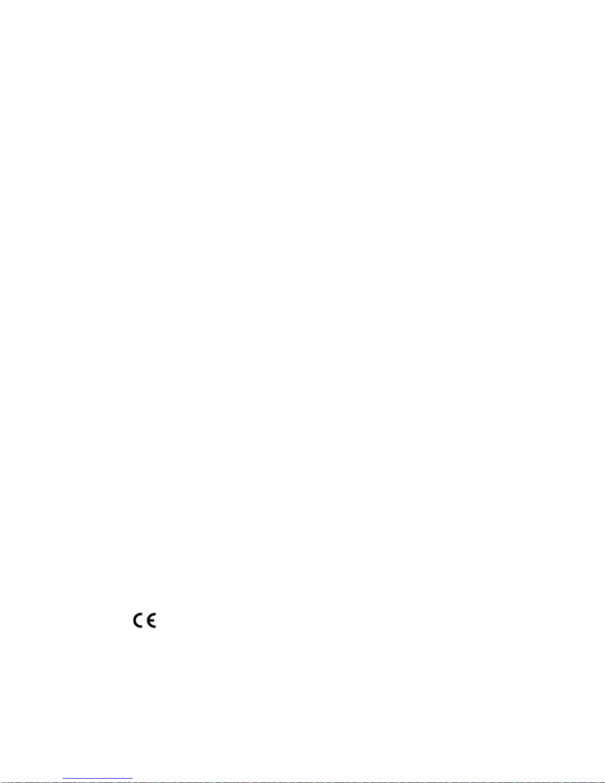
MOUNTING
Mounting Height:
When installed above an electric cooking
appliance the minimum distance between the
surface of the hob elements and the lower
grille of the cooker hood must be 650mm.
When installed above a gas cooking appliance
the minimum distance between the surface of
the hob pan supports and the lower grille of
the cooker hood must be 750mm.
The minimum distance for installation above a
high level grill is 400mm.
The distance between the underside of
adjoining wall cabinet and the worktop must
not be less than 400mm.
If the cooker hood is installed for use above a
gas appliance then the provision for
ventilation must be in accordance with the
gas safety (Installation and use) regulations.
Detailed recommendations are contained in
the following British Standard Codes of
Practice BS6172,BS5440 and BS6891 Current
Edition.
NOTE: This hood has been designed and
approved for installation over an electric
hob with a maximum input of 7kW or a gas
hob with a maximum input of 10kW when
fitted in accordance with the heights
recommended above.
THERMAL CUT-OUT:
WARNING-The fan motor of this appliance
incorporates a thermal cut-out device
which will operate if the hood is installed
below the minimum recommended heights
listed above,or if the motor becomes
overheated.
If the cut-out device is activated,switch off
the fan motor and allow the hood to cool.
The cut-out device will reset itself when the
fan motor has cooled significantly.
Note:the hood is more effective when
installed in extraction (ducting) mode.
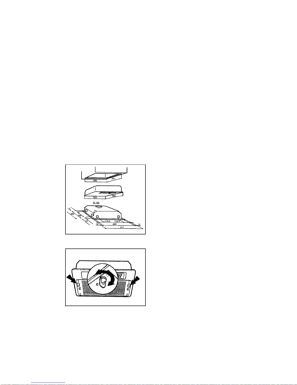
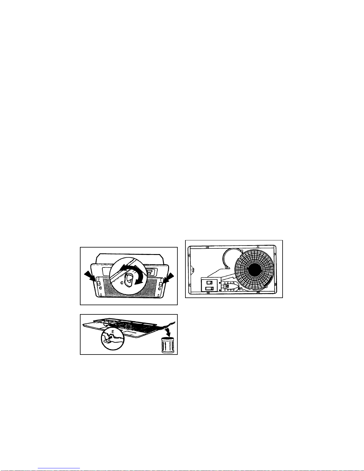
Mounting beneath cabinets on theWall:
Before fitting the hood beneath any type of
wall cabinet/canopy housing,ensure it is
firmly fixed to the wall in accordance with the
manufacturer’s instructions. Before drilling,
care should be taken to check for electric
cables,water pipes or gas pipes on the wall to
which the cabinet/canopy is to be fitted.
The hood may be fixed to any rigid vertical
surface. If the hood can only be fixed to a
hollow construction plaster or partition board
structure,then the wall must be sufficiently
reinforced to be quite rigid in the area of the
housing mounting system.
IMPORTANT: The exhaust air must not be
expelled through a smoke or waste-gas
chimney which is in use or through a shaft
used for ventilating rooms or into the
cavity of a cavity wall or into a cupboard
above the cooker hood.
If the room contains a flued fuel burning
appliance,such as a gas or oil fired central
heating boiler which is not of the‘Balanced
Flue’type,you should make sure that there
is an adequate air inlet into the room at all
times so that fumes from the boiler are not
drawn back into the room by the cooker
hood.
For secure operation and to prevent discharge
gas from coming back in,the vacuum must
not exceed 0.04mbr.
This may be done by making sure the air inlet
into the room passes through non-closing
openings such as air recycling wall boxes,
doors,windows or with other technical
measures.