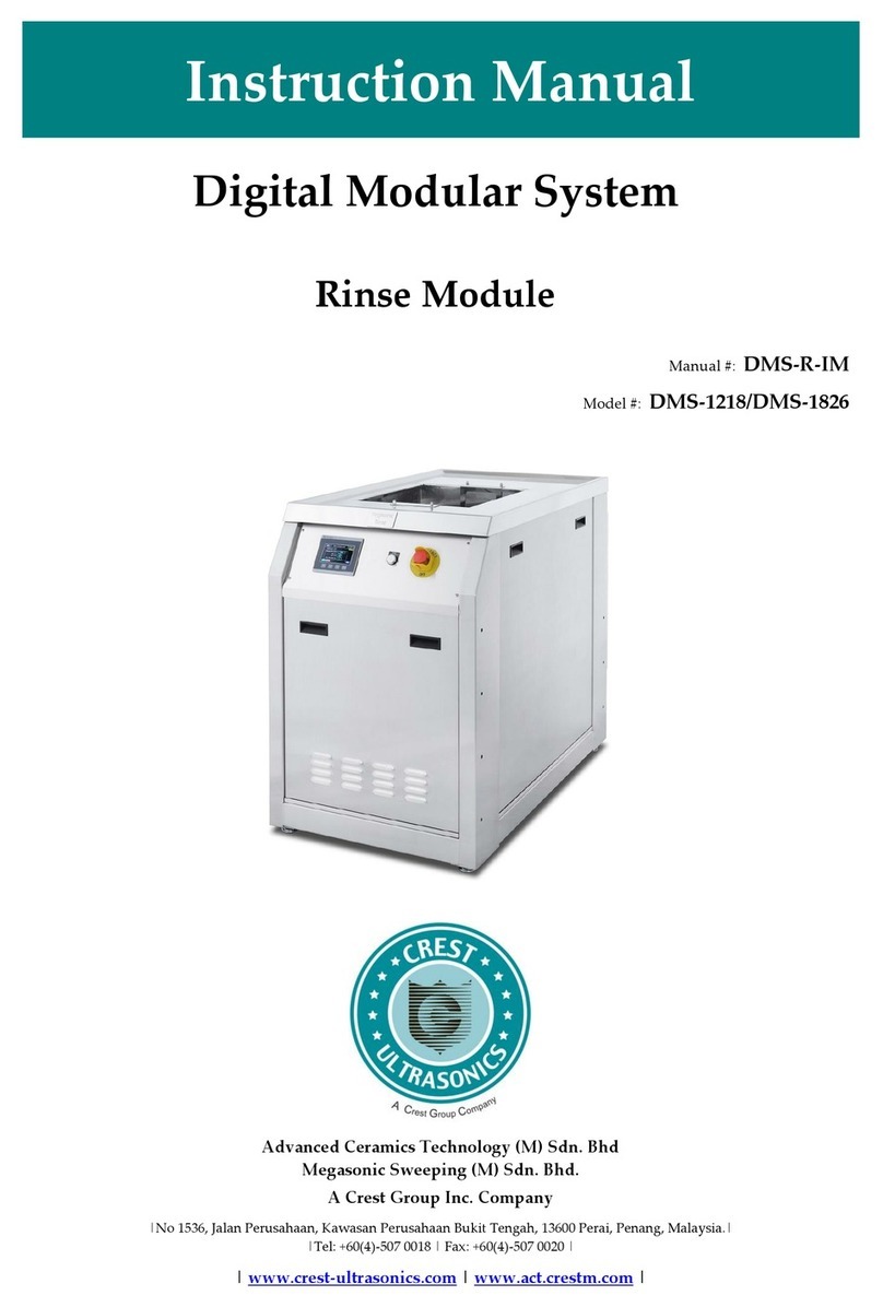
CREST ULTRASONICS DMS-1218 User manual

Instruction Manual
Digital Modular System
Dryer Module
Manual #: DMS-D-IM
Model #: DMS-1218/DMS-1826
Advanced Ceramics Technology (M) Sdn. Bhd
Megasonic Sweeping (M) Sdn. Bhd.
A Crest Group Inc. Company
|No 1536, Jalan Perusahaan, Kawasan Perusahaan Bukit Tengah, 13600 Perai, Penang, Malaysia.|
|Tel: +60(4)-507 0018 | Fax: +60(4)-507 0020 |
| www.crest-ultrasonics.com | www.act.crestm.com |

DMS-D-IM
January 23, 2020 Digital Modular System - Dryer
i
Disclaimer
Care has been taken to ensure the accuracy of the information. No liability can be accepted
for any errors or omissions found in this manual. The publisher of this manual reserves the
right to revise this publication and make changes from time to time in its content without
notice.
Manual Conventions
This manual uses the following typefaces and other special formats to assist you in using
this manual.
Conventions in Text
We use various conventions in text to help you more quickly identify special terms. The
following table describes those conventions and provides examples of their use.
Conventions
Meaning
Example
TEXT
Bold upper case text indicates
STRONG EMPHASIS on a
particular word.
Parts are normally HOT when
they emerge out from the tank.
Text/text
Bold text indicates an emphasis on a
particular word.
Connect fill for rinse stations to
water source or chemical source.
[TEXT]
Bold upper case text enclosed in
brackets indicates keys/buttons to be
pressed on a control panel.
Press [POWER ON]button to
energize the machine.
[Text]
Text enclosed in brackets indicates
keys/buttons press on the user
interface or touch screen.
Click [Esc] or [Enter] to quit.
Text
Italic text indicates references to
headings or titles.
Refer to section 1.12 Lockout
Tagout (LOTO).
Text
Underline text indicates windows
(PC based) or screens (PLC based).
Press on [System Function] to go
to System Function screen.

DMS-D-IM
January 23, 2020 Digital Modular System - Dryer
ii
Danger, Warnings, Cautions, and Notes
DANGER
Danger messages indicate an imminently hazardous situation, which, if
not avoided, is extremely likely to result in death or serious injury. (Note
that this signal word is limited to the extreme situations.)
WARNING
Warning messages indicate a potentially hazardous situation, which, if
not avoided, could result in death or serious injury.
CAUTION
Caution messages indicate a potentially hazardous situation, which, if
not avoided may result in minor or moderate injury. It is also used to
alert the user against unsafe working practices and potential damage to
the system.
NOTE
Note messages provide additional information or helpful tips.
Manual Code
––
V 0123 IM 1 2.
1 2 3 4 5
1
Series
M –Aqueous Ultrasonic Cleaning Machine
V –Ultrasonic Solvent Cleaning Machine
PN –Optimum Console Junior
A –Accessories (Simple cleaning tank or console)
*For standard machine, the model number will be used. Example: F100.
**For Machine built by Crest (US), the Crest (US) job number will be used.
2
Job Number
Job number.
3
Manual Type
IM –Instruction Manual
4
Revision (Major)
Increase when major modification/update done on the manual.
5
Revision (Minor)
Increase when minor modification/update done on the manual.
Feedback on This Manual
If you have any comments on this manual, send email to manual@act.crestm.com giving:
the ACT or crest job number
the document number
the page number, or page numbers, to which your comments apply
a concise explanation of your comments
General suggestions for additions and improvements are also welcome.

DMS-D-IM
January 23, 2020 Digital Modular System - Dryer
iii
Revision History
Manual Code #
Description
DMS-D-IM
First publication.

DMS-D-IM
January 23, 2020 Digital Modular System - Dryer
iv
Table of Contents
DISCLAIMER....................................................................................................................................................... I
MANUAL CONVENTIONS ................................................................................................................................... I
Conventions in Text ...................................................................................................................................... i
Danger, Warnings, Cautions, and Notes....................................................................................................... ii
Manual Code................................................................................................................................................ ii
FEEDBACK ON THIS MANUAL........................................................................................................................... II
REVISION HISTORY .......................................................................................................................................... III
TABLE OF CONTENTS ...................................................................................................................................... IV
1. SAFETY................................................................................................................................................... 1-1
1.1 INTRODUCTION .................................................................................................................................... 1-1
1.2 OPERATOR TRAINING ........................................................................................................................... 1-1
1.3 IMPORTANT SAFETY NOTIFICATIONS .................................................................................................... 1-2
1.4 GENERAL PRECAUTION ........................................................................................................................ 1-4
1.5 LIFTING HAZARDS................................................................................................................................ 1-5
1.6 HEAT/HOT SURFACE HAZARD ............................................................................................................. 1-5
1.7 COMPRESSED AIR HAZARD .................................................................................................................. 1-6
1.7.1 Safety Precautions –Compressed Air ........................................................................................... 1-7
1.7.2 Safe Work Practices –Compressed Air ......................................................................................... 1-8
1.8 MECHANICAL HAZARDS ...................................................................................................................... 1-9
1.9 ELECTRICAL HAZARDS ....................................................................................................................... 1-10
1.10 EMERGENCY OFF (EMO) CIRCUIT................................................................................................. 1-11
1.10.1 Live After EMO .................................................................................................................... 1-12
1.10.2 Recover from Emergency OFF ............................................................................................... 1-12
1.11 SAFETY INTERLOCKS ...................................................................................................................... 1-13
1.11.1 Panel Door Switch Interlock .................................................................................................. 1-14
1.12 LOCKOUT TAG OUT (LOTO).......................................................................................................... 1-15
1.12.1 Lockout Tag out Procedure .................................................................................................... 1-15
1.12.2 Restoring Lockout Tag out..................................................................................................... 1-17
2. SYSTEM OVERVIEW ........................................................................................................................... 2-1
2.1 INTRODUCTION .................................................................................................................................... 2-1
2.2 SYSTEM SPECIFICATIONS....................................................................................................................... 2-2
2.2.1 General System Specifications...................................................................................................... 2-3
2.2.2 Optional Features ........................................................................................................................ 2-6
3. INSTALLATION ................................................................................................................................... 3-1
3.1 CONSOLE UNCRATING AND PLACEMENT ............................................................................................. 3-1
3.2 SYSTEM CLEARANCE............................................................................................................................. 3-2
3.3 HANDLING AND TRANSPORTING.......................................................................................................... 3-3
3.4 FACILITIES REQUIREMENTS ................................................................................................................... 3-4
3.4.1 Interconnect Facility Services....................................................................................................... 3-6
3.5 PLUMBING INSTALLATION .................................................................................................................... 3-7
3.5.1 Step-By-Step Guide...................................................................................................................... 3-8
3.6 ELECTRICAL INSTALLATION ................................................................................................................. 3-9
3.6.1 Interconnect Wire Harness......................................................................................................... 3-11
3.7 AIR/LIQUID FLOW INDICATOR IN PLUMBING...................................................................................... 3-12
3.8 “PROCESS SUPERVISOR”DESIGNATION .............................................................................................. 3-13
4. OPERATION.......................................................................................................................................... 4-1

DMS-D-IM
January 23, 2020 Digital Modular System - Dryer
v
4.1 INTRODUCTION .................................................................................................................................... 4-1
4.2 IMPORTANT SAFETY NOTIFICATIONS .................................................................................................... 4-2
4.3 POWER ON SYSTEM.............................................................................................................................. 4-4
4.4 ALLEN BRADLEY MICRO820 WITH 800 SERIES TERMINAL HMI SCREEN ............................................... 4-6
4.5 LOGIN &LOGOUT ................................................................................................................................ 4-9
4.5.1 Scope of Users............................................................................................................................ 4-11
4.6 TEMPERATURE MONITORING AND SETTING ....................................................................................... 4-12
4.6.1 View and Change Tank Temperature Settings ............................................................................ 4-13
4.7 OPERATING STATION (DRYER STATION)............................................................................................. 4-15
4.7.1 Dryer Station Process Parameters Setup .................................................................................... 4-15
4.7.2 Dryer Station Auto Cycle Drying Process.................................................................................. 4-18
4.8 INFO AND ALARM MESSAGE............................................................................................................... 4-24
4.8.1 Info Message List ....................................................................................................................... 4-25
4.8.2 Alarm Message List ................................................................................................................... 4-25
4.9 RECOVER FROM OVER TEMPERATURE................................................................................................. 4-26
4.10 POWER OFF SYSTEM ...................................................................................................................... 4-28
4.11 EMERGENCY OFF........................................................................................................................... 4-29
4.12 REMOTE AND LOCAL MODE........................................................................................................... 4-30
4.13 AUTO/MANUAL MODE.................................................................................................................. 4-34
4.14 DECOMMISSIONING PROCEDURE.................................................................................................... 4-36
4.15 OPERATING PROCEDURE DURING ACCIDENT OR BREAKDOWN ...................................................... 4-37
5. INTERPRETING HMI........................................................................................................................... 5-1
5.1 MAIN MENU SCREEN ........................................................................................................................... 5-1
5.2 AUTO SCREEN ...................................................................................................................................... 5-3
5.2.1 Auto Screen (System in Auto mode operation and Remote mode).................................................. 5-4
5.3 ALARM HISTORY .................................................................................................................................. 5-5
5.4 RECIPE SETTING.................................................................................................................................... 5-6
5.5 TEMPERATURE CONTROL SCREEN ........................................................................................................ 5-8
5.6 MANUAL FUNCTION .......................................................................................................................... 5-10
5.7 MISCELLANEOUS PARAMETERS .......................................................................................................... 5-13
5.7.1 Misc. 1 Screen ........................................................................................................................... 5-13
5.7.2 Misc. 2 Screen ........................................................................................................................... 5-14
5.7.3 Misc. 3 Screen ........................................................................................................................... 5-15
5.8 AUTO OPTIONS SCREEN ..................................................................................................................... 5-16
5.9 DIGITAL I/O STATUS........................................................................................................................... 5-17
6. PREVENTIVE MAINTENANCE ......................................................................................................... 6-1
6.1 INTRODUCTION .................................................................................................................................... 6-1
6.2 IMPORTANT SAFETY NOTIFICATIONS .................................................................................................... 6-1
6.3 BUDDY SYSTEM..................................................................................................................................... 6-3
6.4 COMPONENTS MAINTENANCE ............................................................................................................. 6-3
6.5 PM FOR TANK...................................................................................................................................... 6-4
6.5.1 General Check.............................................................................................................................. 6-4
6.6 PM FOR PANEL DOOR SWITCH............................................................................................................. 6-5
6.7 PM FOR ELECTRICAL............................................................................................................................ 6-6
6.8 PM FOR HOT AIR DRYER ..................................................................................................................... 6-7
6.8.1 Change Pre-Filter/HEPA Filter.................................................................................................... 6-8
6.8.2 Differential Pressure Switch Functionality Check......................................................................... 6-9
6.8.3 Differential Pressure Switch Setting Procedure .......................................................................... 6-10
6.8.4 General Check............................................................................................................................ 6-11
6.8.5 HEPA Filter and Pre-filter Installation Procedure...................................................................... 6-11
6.9 PM FOR CDA FR (FILTER REGULATOR) ............................................................................................. 6-18
6.10 PM CHECK ON EMO BUTTON........................................................................................................ 6-19
6.11 PM FOR TEMPERATURE CONTROLLER (THERMOSTAT)................................................................... 6-20

DMS-D-IM
January 23, 2020 Digital Modular System - Dryer
vi
7. TROUBLESHOOTING......................................................................................................................... 7-1
7.1 CORRECTING PROBLEMS ....................................................................................................................... 7-1
8. APPENDIX ............................................................................................................................................. 8-1
8.1 SYSTEM PASSWORD............................................................................................................................... 8-1
8.2 DATE AND TIME SETTING ..................................................................................................................... 8-2
8.3 ADMINISTRATION LOGIN ..................................................................................................................... 8-4
8.4 TEMPERATURE PRESENT VALUE OFFSET SETTING................................................................................. 8-5
8.5 MACHINE SETUP .................................................................................................................................. 8-6
8.6 RESISTANCE TEMPERATURE DETECTOR (RTD) CALIBRATION PROCEDURE .......................................... 8-9
8.7 H2 ASSEMBLY DRAWING.................................................................................................................... 8-10
9. ENVIRONMENTAL PROTECTION/DISPOSAL.............................................................................. 9-1
9.1 DISPOSAL AND RECYCLING .................................................................................................................. 9-1
9.2 GOVERNMENTAL REGULATORY BODIES ............................................................................................... 9-1

DMS-D-IM Safety
January 23, 2020 Digital Modular System - Dryer
1-1
1. Safety
1.1 Introduction
WARNING
Operating the system with any portion of the safety systems
or procedures bypassed can result in severe system damage
and human injury.
Extreme care and considerations were taken during the design and
implementation of this system for a safe operation of this system by operators.
However, it is mandatory that users are aware of hazards highlighted in this
entire section to avoid incidents that may cause system damage or even human
injury.
1.2 Operator Training
Drying system should be used only by personnel specifically trained for their
use. This training should include electrical safety, machine operation and
emergency procedures.

DMS-D-IM Safety
January 23, 2020 Digital Modular System - Dryer
1-2
1.3 Important Safety Notifications
DANGER
Electrical Hazard: Hazardous voltage. May cause electrical
shock or burn!
High voltages exist in this machinery when the electrical
power is turned on. Always disconnect power when servicing
machine. When operating the system, observe all practical
precautions for the use of high voltage machinery, as dictated
by applicable electrical codes and regulations. Observe all
operating precautions as they are stated throughout this
manual.
WARNING
Never place your hands, arms, or any body part in the tank
when drying system is in operation. Always use racks,
baskets, or tongs for inserting and removing objects from the
tank.
WARNING
Before working with any part of this drying system, you must
tightly secure loose hair, jewellery, loose clothing and other
personal effects that may be drawn into or damaged by
moving parts of the machinery. Failure to do this may result
in property damage and/or serious personal injury.
Also, be careful to avoid pinch injuries to fingers when
working near moving parts of the machine.
WARNING
Countertops on the console can become HOT after extended
periods of operation. Use protective gloves and other
protective clothing.
WARNING
Tank walls remain hot for a period of time after the machinery
is turned off. Therefore, you should exercise appropriate
caution when performing cleaning and maintenance
operations. Wear gloves and other protective clothing, or wait
until the tank walls have cooled.

DMS-D-IM Safety
January 23, 2020 Digital Modular System - Dryer
1-3
WARNING
The drying system generates heat above 200°F. Therefore,
parts that have been dried will be extremely HOT. Do not
touch them with bare hands until cooled; or, use protective
gloves.
NOTE
Please read through Safety chapter before carrying out
installation, operation or maintenance of this system.

DMS-D-IM Safety
January 23, 2020 Digital Modular System - Dryer
1-4
1.4 General Precaution
Several hazards may be present when operating or servicing the system and
extreme caution must be exercised at all times.
The hazards that may be encountered include:
Electrical hazards
Mechanical hazards
Lifting hazards
Compressed air hazards
Heat and hot surface hazards
Existence of hazards on this system is indicated by the use of safety labels that
are fixed in a visible manner.
The use of controls, replacement parts, adjustments or procedures other than
those specified within this manual may result in exposure to any of these
hazards.
The degree of seriousness of the hazards is indicated by the use of the following
signal words:
DANGER
Indicates an imminently hazardous situation, which, if not
avoided, is extremely likely to result in death or serious
injury. (Note that this signal word is limited to the extreme
situations.)
WARNING
Indicates a potentially hazardous situation, which, if not
avoided, could result in death or serious injury.
CAUTION
Indicates a potentially hazardous situation, which, if not
avoided may result in minor or moderate injury. It is also
used to alert the user against unsafe working practices and
potential damage to the system.

DMS-D-IM Safety
January 23, 2020 Digital Modular System - Dryer
1-5
1.5 Lifting Hazards
WARNING
Heavy Object:
For manual handling for load of more than 5
kg, the user should find a solution to lift the
load and also considering the frequency of
loading cycles.
Recommend to use proper lifting aids when
moving or lifting.
PPE
1.6 Heat/Hot Surface Hazard
WARNING
Tank walls remain HOT for a period of time
after the machinery is turned off.
Therefore, you should exercise appropriate
caution when performing cleaning and
maintenance operation.
Wear gloves and other protective clothing,
or wait until the tank walls have cooled.
PPE
WARNING
Countertops on the console can become
HOT after extended periods of operation.
Use protective gloves and other protective
clothing.
PPE

DMS-D-IM Safety
January 23, 2020 Digital Modular System - Dryer
1-6
WARNING
Hot Surface Hazard
The drying system may exceed 50C.
Therefore, parts that have been dried will be
HOT. Do not touch them with bare hands
until cooled; or, use protective gloves.
PPE
WARNING
Hot Surface hazard (Applies to system
with Dryer)
The drying system generates heat above
200F (90C); therefore, parts that have been
dried will be extremely HOT. Do not touch
them with bare hands until cooled; or, use
protective gloves.
PPE
1.7 Compressed Air Hazard
WARNING
Compressed Air Hazard: Lockout source and bleed off
pressure before servicing equipment.
CAUTION
Compressed Air Hazard. Compressed air is used in this
system to provide power like shutter door, tank lid, and
conveyor stopper and so on.
Recommended compressed air pressure: 5-6 bar (80-90psi)

DMS-D-IM Safety
January 23, 2020 Digital Modular System - Dryer
1-7
1.7.1 Safety Precautions –Compressed Air
The following precautions pertain to the use of compressed air devices:
All pipes, hoses, and fittings must have a rating of the maximum pressure
of the compressor. Compressed air pipelines should be identified (psi) as
to maximum working pressure.
Air supply shutoff valves should be located (as near as possible) at the
point-of-operation.
Air hoses should be kept free of grease and oil to reduce the possibility of
deterioration.
Hoses should not be strung across floors or aisles where they are liable to
cause personnel to trip and fall. When possible, air supply hoses should
be suspended overhead, or otherwise located to afford efficient access
and protection against damage.
Hose ends must be secured to prevent whipping if an accidental cut or
break occurs.
Pneumatic impact tools, such as riveting guns, should never be pointed at
a person.
Before a pneumatic tool is disconnected (unless it has quick disconnect
plugs), the air supply must be turned off at the control valve and the tool
bled.
Compressed air must not be used under any circumstances to clean dirt
and dust from clothing or off a person’s skin. Shop air used for cleaning
should be regulated to 15 psi unless equipped with diffuser nozzles to
provide lesser pressure.
Goggles, face shields or other eye protection must be worn by personnel
using compressed air for cleaning equipment.
Static electricity can be generated through the use of pneumatic tools.
This type of equipment must be grounded or bonded if it is used where
fuel, flammable vapors or explosive atmospheres are present.

DMS-D-IM Safety
January 23, 2020 Digital Modular System - Dryer
1-8
1.7.2 Safe Work Practices –Compressed Air
The following is a summary of safe work practices that should be followed
when using compressed air:
Ensure that excessive pressure and chip fly back hazards are effectively
controlled.
Always wear the appropriate personal protective equipment. As stated
previously, eye protection must be worn when using compressed air.
Never use compressed air to clean clothing or the body. This greatly
increases the risk of an air gun directly contacting the body. Particles can
also easily become dislodged and enter the skin or eyes. Use a safe
alternative such as a brush or vacuum tool.
Never participate in horseplay with compressed air. Never point an air
gun or direct air toward another individual.
Never tamper with air guns or modify them in any way. Homemade
devices added to air guns usually increase the potential for injury.

DMS-D-IM Safety
January 23, 2020 Digital Modular System - Dryer
1-9
1.8 Mechanical Hazards
WARNING
Pinch Point And Mechanical Entanglement Hazards: Will
result in injury to fingers/hand if placed in machine. Keep
fingers/hand out of the system. Turn power off and lockout
tag out before servicing.
Trip Hazard!
Please be careful that the CDA supply hose and exhaust
ducting are extended out from the rear of the system and may
cause tripping.
Extreme care and consideration were taken throughout the development of this
system for the safe operation of the equipment and operator. However, it is
mandatory that users observe extreme care to avoid situations that may
endanger life or cause injury. Therefore, it is essential to take the following
precautions:
Do not wear loose fitting clothing, neckties or jewelry that could become
entangled in moving parts.
Do not try to remove piece parts from a moving handling system.
Ensure that only trained and qualified personnel are permitted within the
working zone of the equipment.
Identify the working zone of the equipment with floor marking, signs and
barriers.
Eliminate areas where personnel might be trapped between moving and
fixed parts of the equipment (pinch points).
Provide sufficient room to permit safe training and maintenance
procedures.
Always adhere to local or company safety regulations.
Report to the appropriate authorities should any unsafe condition is
found around the area of the equipment.

DMS-D-IM Safety
January 23, 2020 Digital Modular System - Dryer
1-10
1.9 Electrical Hazards
Electrical Hazard: Hazardous voltage. May cause electrical
shock or burn. Refer to electrical drawing for more detail.
Disconnect and lockout tag-out system. Wait for at least 15
minutes after main supply is disconnected prior to servicing
this system.
WARNING
Power to this system is provided by
DMS-1218: 240VAC / 3-phase/ 60Hz / 21Amps
DMS-1826: 240VAC / 3-phase/ 60Hz / 36Amps
Disconnect and lockout tag out (LOTO) system prior to any
servicing.
General Electrical Safety:
Only trained and certified personnel should remove covers.
Ensure that only trained personnel, familiar with electrical hazards, have
access to the inside of the system.
Follow accepted working procedures and code of practice when working on
electrical components.
Follow the requirements of the electrical safety code for the site where the
system is installed.
Read the operating instructions of the system before commencing any
servicing.
Never wear rings, bracelets or other jewelry when working around electrical
circuits.
Never work on electrical equipment alone. Always have a colleague nearby.
Isolate the main power input at the circuit breaker, lock it in the OFF
position and attach a notice to the circuit breaker before replacing fuses or
exchanging printed circuit boards (PCB).
Never operate the system if any main power cable is frayed or damaged.
Never operate the system in production with safety covers removed.
Never assume the polarities of cabling or replacement components.

DMS-D-IM Safety
January 23, 2020 Digital Modular System - Dryer
1-11
1.10 Emergency OFF (EMO) Circuit
WARNING
Maintenance CAN only be performed after LOTO (Lockout &
Tag out) to the system.
Please refer section 1.12 Lockout Tag out (LOTO) for procedure.
The EMO Circuit is used to place the system into a safe shutdown condition,
without generating any additional hazard to personnel or the facility when the
[EMO] button is activated. Those [EMO] buttons should be clearly labeled and
clearly legible from the viewing location.
There is one type of [EMO] button used in the system.
Non-key-lockable, Self-latching with red, round mushroom head located
at dryer console control panels.
Figure 1-1: [EMO] button
Please refer to figure below for [EMO] actuators location.
Figure 1-2: Non-key-lockable, self-latching with red, round mushroom head at control panel for
Dryer Station
Non-key-
lockable EMO
button

DMS-D-IM Safety
January 23, 2020 Digital Modular System - Dryer
1-12
1.10.1 Live After EMO
NOTE
Please refer to relevant electrical drawing or schematic for
more detail.
The EMO circuit, when activated, shuts off all energy to the system EXCEPT:
Power Supply Input 240VAC Output 24VDC 2.5A
Noise Filter
PLC
Refer to electrical schematics for more information.
Do not touch any other components listed above as these components are still
energized.
1.10.2 Recover from Emergency OFF
Follow instruction below to recover from emergency OFF:
Step
Description
1
Rectify and solve the problem.
2
Release [EMO] button by turning [EMO] (red button) button
clockwise until the button pops out.
3
Press on [SYSTEM ON] button and follow operating instruction in
section 4.

DMS-D-IM Safety
January 23, 2020 Digital Modular System - Dryer
1-13
1.11 Safety Interlocks
WARNING
Do not bypass any of the equipment safety interlocks
NOTE
Make sure front and rear panels are closed properly and
[EMO] button is released before press [SYSTEM ON] button
at touch screen.
Safety interlocks have primary function to protect the equipment user from any
hazardous conditions that are present in the equipment.
Crest strongly discourages any attempts to bypass this equipment safety
interlocking features under any conditions as these actions would render the
equipment unsafe.
The following safety features have been built into the system:
Panel Door Switch
Other manuals for DMS-1218
1
This manual suits for next models
1
Table of contents
Other CREST ULTRASONICS Cleaning Equipment manuals
