Flowplant 320 Series Use and care manual

320 SERIES
Quick Reference Service Guide –Rev 2

INDEX
1) TECHNICAL SPECIFICATION
2) SCHEMATICS
3) WIRING DIAGRAM
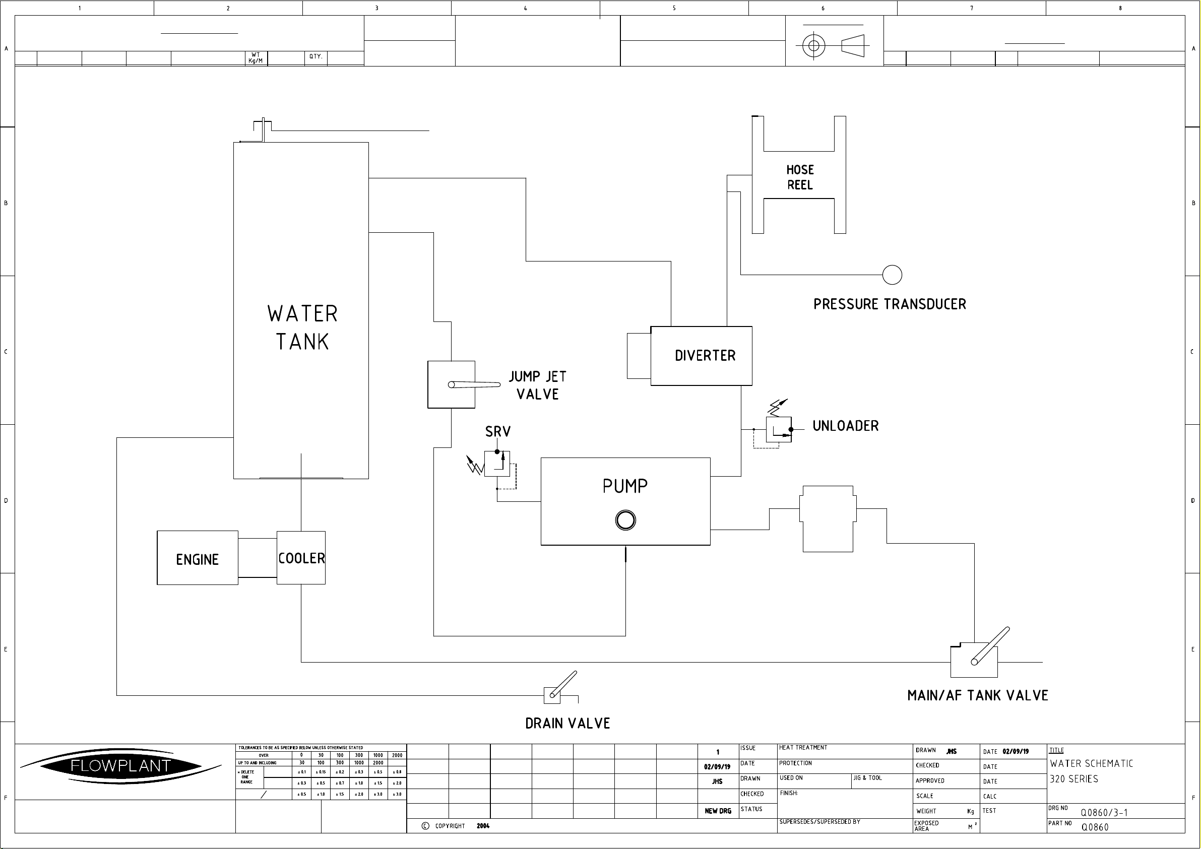
4) WATER DIAGRAM
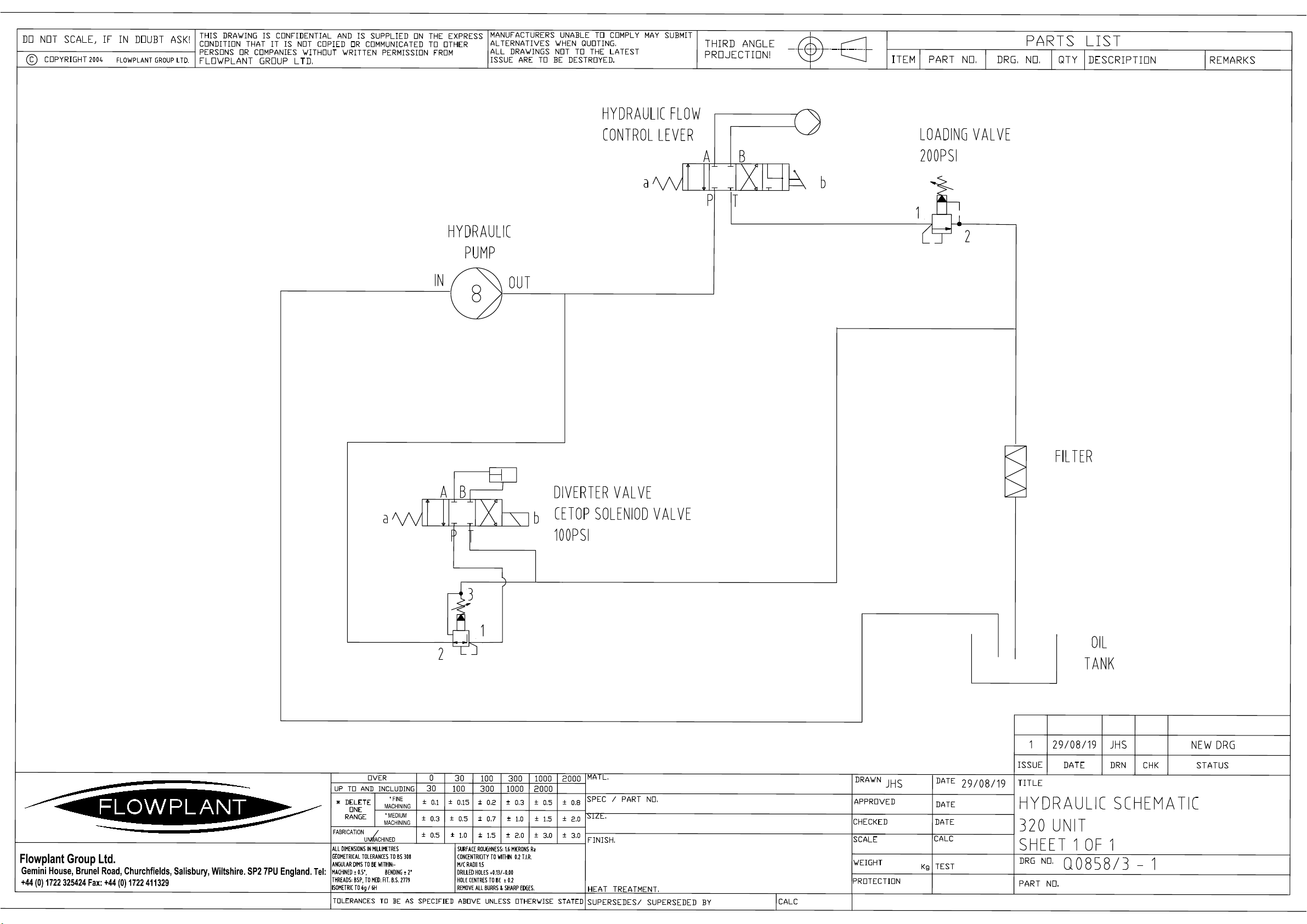
5) HYDRAULIC DIAGRAM
6) OPERATOR QUICK START GUIDE
7) SPARES LIST
8) SERVICE SCHEDULE
9) TROUBLESHOOTING
10) TELERADIO PAIRING
11) ALARM FAULT CODES
REVISION
DESCRIPTION
REFERENCE
SIGNED
DATE
0
FIRST ISSUE
N/A
JHS
04/09/19
1
RELEASE DAY UPDATES
JHS
2
SPARES UPDATE
SAS
06/04/21

1) TECHNICAL SPECIFICATION –320 SERIES
Engine …KUBOTA D1105
Pump …SPECK NP25
Flow …54 LPM / 45 LMP
Pressure …3000 PSI / 2500 PSI
Weight …500 KG
Dimensions …1250MM LONG X 1200MM WIDE X 1190MM HIGH
Hose Size …½” 91.44 M – 055-021 (STANDARD)
Hose Reel …HYDRAULIC
Radio System …TELERADIO 433 MGHZ CAN OPEN TG2
Tank Capacity …
400 / 650 L
Voltage …12 V DC
Control System …MURPHY MPC-20
Suggested Accessories …SEE SPEC SHEET
Jet Sizes Approximate …SEE JET SIZER

2) SCHEMATICS –320 SERIES

REMOVABLE
GRP CANOPY
CANOPY SUPPORT
CANOPY LATCHES
CANOPY LATCHES
ENGINE COOLER
GUARD
WATER FILTER
TANK FILL
400 LITRE
WATER TANK
HYDRAULIC TANK
HOSE FEED GUIDE
INLET HOSE
REEL
HOSE REEL
BATTERY
ENGINE PUMP
CONTROL VALVE
JUMP JET
HYDRAULIC DIVERTER
VALVE
MPC CONTROL
PANEL AND
ENCLOSURE
DIESEL TANK
ANTIFREEZE TANK
DRAIN
VALVE
GEARBOX
PRESSURE SENSOR
ANTI FREEZE VALVE

AIR FILTER
EXHAUST OUTLET
STARTER MOTOR
ALTERNATOR
OIL FILTER
SUMP PLUG
OIL PRESSURE SWITCH
FAN BELT
DIP STICK
OIL FILL
THERMOSTAT
MANUAL
LIFT PUMP
FUEL INLET
THROTTLE
FUEL SOLENOID
MAGNETIC PICK UP
LOCATED ON FLYWHEEL HOUSING
FUEL RETURN
GLOW PLUG
CONNECTION

3) WIRING DIAGRAM –320 SERIES

* FINE
MACHINING
FABRICATION
UNMACHINED
* MEDIUM
MACHINING
Flowplant Group Ltd.
Gemini House, Brunel Road, Churchfields, Salisbury, Wiltshire. SP2 7PU England.
Tel:
+44 (0) 1722 325424 Fax: +44 (0) 1722 411329

* FINE
MACHINING
FABRICATION
UNMACHINED
* MEDIUM
MACHINING
Flowplant Group Ltd.
Gemini House, Brunel Road, Churchfields, Salisbury, Wiltshire. SP2 7PU England.
Tel:
+44 (0) 1722 325424 Fax: +44 (0) 1722 411329

4) WATER DIAGRAM –320 SERIES
INFORMATION FOR ESTIMATION OF WEIGHT AND COST ONLY
MATERIAL LIST
ITEM PART NO. MATERIAL SPEC SIZE mm Kg
LENGTH TOTAL WT
PARTS LIST
ITEM PART No. DRG. No QTY DESCRIPTION REMARKS
A B C D E F G H J K
L M N P R S T U V W
X Y Z
Gemini House, Brunel Rd, Churchfields,
Salisbury, Wiltshire, England. SP2 7PU
Tel: (01722) 325424 Fax: 01722 411329
ALL DIMENSIONS IN MILLIMETRES
GEOMETRICAL TOLERANCES TO BS 308
ANGULAR DIMS TO BE WITHIN:-
MACHINED ± 0.5°, BENDING ± 2°
THREADS: BSP, TO MED. FIT. B.S. 2779
ISOMETRIC TO 6g / 6H
FABRICATION
UNMACHINED
* MEDIUM
MACHINING
* FINE
MACHINING
SURFACE ROUGHNESS: 1.6 MICRONS Ra
CONCENTRICITY TO WITHIN 0.2 T.I.R.
M/C RADII 1.5
DRILLED HOLES +0.13/-0.00
HOLE CENTRES TO BE ± 0.2
REMOVE ALL BURRS & SHARP EDGES.
DO NOT SCALE
IF IN DOUBT ASK !
MANUFACTURERS UNABLE TO COMPLY MAY
SUBMIT ALTERNATIVES WHEN QUOTING.
ALL DRAWINGS NOT TO THE LATEST
ISSUE ARE TO BE DESTROYED.
Flowplant Group Ltd.
Flowplant Group Ltd.
THIS DRAWING IS CONFIDENTIAL AND IS SUPPLIED
ON THE EXPRESS CONDITION THAT IT IS NOT
COPIED OR COMMUNICATED TO OTHER PERSONS
OR COMPANIES WITHOUT WRITTEN PERMISSION
FROM FLOWPLANT GROUP LTD.
Third angle projection
L E A D E R S I N C L E A N I N G T E C H N O L O G Y

5) HYDRAULIC DIAGRAM –320 SERIES
* FINE
MACHINING
FABRICATION
UNMACHINED
* MEDIUM
MACHINING
Flowplant Group Ltd.
Gemini House, Brunel Road, Churchfields, Salisbury, Wiltshire. SP2 7PU England.
Tel:
+44 (0) 1722 325424 Fax: +44 (0) 1722 411329
2
1
2
1
3
6) OPERATOR QUICK START GUIDE
–320 SERIES Desilter
START UP
1) Perform all daily checks as detailed in service schedule and manual.
2) Ensure vehicle handbrake is applied. Connect to water supply.
3) Feed the end of the high-pressure hose through the hose trace.
4) Ensure the high pressure hose is in a safe position, preferably in sight.
5) Switch the master rocker switch to the on position (1).
6) Enter the 4 digit PIN using arrows and return button.
7) Press the green start button. The engine will start automatically, and idle.
JETTING
8) Adjust speed using RPM+ or RPM- buttons, to medium revs (i.e 1600 RPM).
9) To divert water to the high pressure (or back to tank) hose press yellow spray button .
10) Then readjust the speed to increase or reduce pressure.

RADIO CONTROL
11) Press the radio button on the main controller. The display will show “remote enabled”.
12) Pull out the red button on the base of the remote control handset.
13) Adjust speed / pressure using RPM+ “HI” and RPM- “LO” buttons.
14) To divert water to the high pressure (or back to tank) hose press yellow spray button .
SHUT DOWN
15) Adjust speed using RPM+ or RPM- buttons, to medium revs (i.e 1600 RPM).
16) Reduce the RPM to the idle speed using the RPM- / “LO” buttons.
17) Divert the water to tank using the button
18) Engine speed will automatically reduce to idle.
19) Press the red engine stop button to stop the engine.
20) To turn off the whole unit, switch the master rocker switch to the off position (0).
EMERGENCY / RAPID SHUT DOWN
21) Depress either the emergency stop button located on the unit next to the control system,
or (if in use) depress the emergency stop button on the base of the remote contol handset.

AUTOMATIC SHUT DOWN
22) The engine and unit as a whole will automatically shut down if the monitoring and control
system detects a malfunction or operating issue.
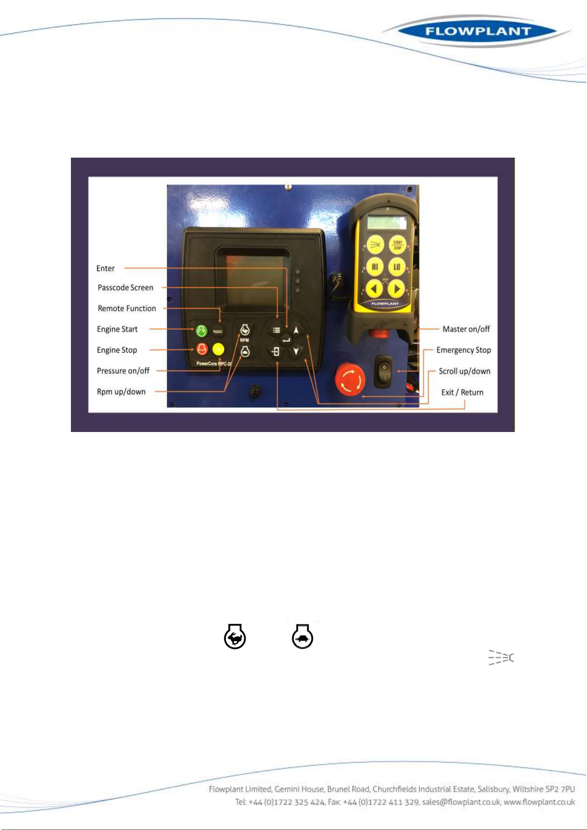
The below notes are to add in the understanding and navigation of the screens contained within the
Murphy MPC-20 Controller. MPC-20 Screen Display Sequence: -
Powering up the display screen: -
NB…when the E-stop circuit is activated, all power will be blocked to the control panel.
To power up the control panel, ensure the E-stop button is deactivated with the twist lock out.
switch the power on by pressing the master rocker switch located on the RHS, below the main
control panel to the 1 position. The three LED lights on the RHS of control screen will come on to
indicate that they work then screen will now power up and will prompt the entering of a passcode.
The three LED’s will indicate the following.
RED …Shutdown Alarm active
Amber …Warning Alarm
Green …Auto Mode
The screen will also indicate any alarm state that would prevent unit operation (i.e. water tank
empty) the screen will indicate the alarm and that it needs to be acknowledged and silenced by
pressing the enter/return button. Also, a STOP indication symbol will appear in the lower RHS of
screen, and the red LED on the control panel will be on and will prevent engine start.
To enter a passcode
NB…Normally when first switched on, the digit to the far RHS is highlighted.
1. Press enter/return on the control cursors to move highlighted digit to the far LHS
2. Press the up arrow on control cursors to advance digital to the required number
3. Press enter/return to select that digit and move to the next digit
4. Repeat the process until all four digits are entered
5. Press enter/return and the screen will then show the main screen
6. Indicating the flowplant logo, unit pressure, set temperature, engine RPM and engine status.
Passcodes: -
There are two passcodes that are used on this the MPC-20 controller.
•2010…Entree level passcode, give a basic entree level to the most basic of operation i.e.
operational screens
•1111…Low security level passcode, gives a more interactive entry level giving means of
changing minor settings, dates and times etc.
To enter a passcode level first press the main screen/passcode button. Then enter the required
passcode using the procedure listed above.

NB…The entree level code must have been entered before secondary levels and the engineering
level can be selected.

Display Screen’s: - (passcode…2010)
On entering this passcode, the following operational screens and accessible…
NB…these screens are only status displays and not settings that can be changed
NB…To navigate and access required screen, press the up/down arrow buttons to move through
the list of screens until the desired screen is indicated. Then press enter/return button
To navigate within the screen use of up/down arrows to move through screen list, then press the
enter/return button to access the parameter settings.
Press the return button to exit parameter settings or press the passcode button to return to main
home screen.
1. Main Screen...Indicating flowplant logo, unit pressure (Bar), engine RPM and engine status, with
a pressure indicating percentage bar along the bottom of the screen.
2. Operational Screen…12 box screen indicating the operational state of the unit
Box 1…Actual RPM…Display’s the actual RPM of the engine.
(via the signal from the magnetic pickup)
Box 2…Target RPM…Display’s the required set RPM of the unit.
(set by the operator via the speed up/down cursor button)
Box 3…Engine Battery… Display’s the voltage within the battery and the battery charging
voltage.
Box 4…Run Hours…Display’s the current run hours for the unit.
Box 5…Engine Status…Display’s the operational status of the engine, (i.e., Loaded,
Spindown, Stabilise, Stopped)
Box 6…Status Time…Display’s the countdown status of not active operations?
(countdown for 30mins)
Box 7…Remote…Display’s the operational state of the remote system. (i.e. Remote
Disabled, Remote enabled)
Box 8…Water…Display’s the operational state of the jetting sequence (i.e. OFF/ON)
Box 9…Time…Display’s time (Rear time)
Box 10…Date…Display’s Date (Rear Date)
Box 11…Unit Pressure…Display’s unit operating pressure (Displayed in Bar)
Box 12…Not Used…
3. Digital Input Status Screen…Indicates the operational status of the digital inputs received by
the controller. (when unit in non-operational state)
DI 1 Disabled Open
DI 2 Disabled Open
DI 3 Disabled Open
DI 4 Tank Empty Neg
DI 5 Disabled Open
DI 6 Low Oil Pressure SW Neg

4. Relay Status Screen…Indicates the status of the internal solid-state relays within the control
panel. (when unit in non-operational state)
R1 Crank Off
R2 Fuel Off
R3 Pre-Heat Relay Off
R4 Water Diverter Solenoid Off
R5 Not Used Off
R6 Not Used Off
5. Analog Input Status Screen…Indicates the status of the Analog signals received by the
controller. (when unit in non-operational state)
AI 1 Disabled
AI 2 Disabled
AI 3 Flowplant Water Pressure
AI 4 Engine Temperature
AI 5 Disabled
AI 6 Disabled
AI 7 Disabled
AI 8 Disabled
6. System Info Screen…Indicates general system info,
(i.e. time, day, date, P/N number, Serial Number, etc.)
Display Screen’s: - (passcode…1111)
On entering this passcode, the following setting screens and accessible…
NB…these screens allow access to minor level settings that can be changed
NB…To navigate and access required screen, press the up/down arrow buttons to move through
the list of screens until the desired screen is indicated. Then press enter/return button
To navigate within the screen use of up/down arrows to move through screen list, then press the
enter/return button to access the parameter settings.
Press the page back (enter Pic) button to exit parameter settings or press the home/passcode
button (enter pic) to return to main home screen.
1. First level Setting Screen…indicating the following setting screens for the unit
Flowplant Settings…allows access to the ‘Start Alarm Silence’ settings
System…allows access to the ‘Date/Time’ and the ‘Backlight’ settings.
Engine Settings…no access to these settings on this level entree
Advanced Engine Settings…no access to these settings on this level entree

Flowplant Settings…
Start Alarm Silence…
Start Alarm Silence…
Start alarm silence on…will silence the start-up siren (default is siren on)
Display Actual Temperature…
Display Actual Temperature…Displays actual temperature on main temperature screen
Hide Actual Temperature…Hides actual temperature on temperature screen (default)
System…
Date/Time…
Time…
Date…
Backlight…
Brightness…
Other manuals for 320 Series
2
This manual suits for next models
2
Table of contents
Other Flowplant Cleaning Equipment manuals


Popular Cleaning Equipment manuals by other brands


Alfalaval
Alfalaval GJ Tote Blast Station instruction manual

IPC Eagle
IPC Eagle HighPure HP 0 instruction manual

AU Tool
AU Tool CT150 user manual

Alfalaval
Alfalaval Toftejorg SaniJet 25 instruction manual

Silvercrest
Silvercrest SRB 6 A1 384456 2107 Operating instructions and safety instructions

e.ziclean
e.ziclean Cyclosteam P310 manual


