CRG CDM8240 User manual
Service Manual
CDM8240
(Level 2)
SN:YT2.291.036WHSC-JX2
Version:v1.0
Released date:2009-06-25

YT2.291.036WHSC-JX2
Revision Record
Version Date Page Description
V1.0 Jun. 2009 All Initial release
CDM8240 Sevice manual(Level 2) page i of iv

YT2.291.036WHSC-JX2
Contents
1NOTE FEEDER...............................................................................1
1.1 TOOLS................................................................................................................2
1.1.1 Standard service tools
..................................................................................2
1.1.2 Cleaning tools
..............................................................................................2
1.2 DISMOUNTING PARTS.............................................................................................3
1.2.1 Removing the note feeder
.............................................................................3
1.2.2 Removal of outter transport assembly
............................................................3
1.2.3 Removal of localizer, eccentric cam and eccentric cam fork
.............................4
1.2.4 Removal of counter rotating roller (CRR) assembly
.........................................4
1.2.5 Removal of upper transport assembly
............................................................5
1.2.6 Removal of lower transport assembly
............................................................6
1.2.7 Removal of pick motor
..................................................................................7
1.2.8 Removal of pick and separate assembly
........................................................8
1.2.9 Removal of gear and timing pulley
.................................................................9
1.2.10 Removal of transport shaft assembly
...........................................................10
1.3 REPLACING PARTS ..............................................................................................11
1.3.1 Replacement of gear and timing pulley
........................................................11
1.3.2 Replacement of pick motor
.........................................................................12
1.3.3 Replacement of CRR
.................................................................................13
1.3.4 Replacement of CRR guide plate
................................................................16
1.3.5 Replacement of elastomer assembly
...........................................................16
1.3.6 Replacement of pick and separate assembly
................................................17
1.3.7 Replacement of acceleration roller
...............................................................17
1.4 NF CLEANING ITEM..............................................................................................18
2NOTE CASSETTE.........................................................................19
2.1 TOOLS..............................................................................................................20
2.1.1 Standard service tools
................................................................................20
2.2 DISMOUNTING AND REPLACING PARTS.....................................................................20
2.2.1 Replacement of cassette ID magnet
............................................................20
2.2.2 Replacement of push spring
........................................................................21
3NOTE TRANSPORT......................................................................26
3.1 TOOLS..............................................................................................................27
3.1.1 Standard service tools
................................................................................27
3.2 DISMOUNTING PARTS...........................................................................................27
CDM8240 Sevice manual(Level 2) page ii of iv

YT2.291.036WHSC-JX2
3.2.1 Remove the note transport (NT)
..................................................................27
3.2.2 Removal of transport cover
.........................................................................27
3.2.3 Removal of count sensor holder and cable holder
.........................................28
3.2.4 Removal of solenoid assembly
....................................................................28
3.2.5 Removal of gear and count disk
..................................................................29
3.2.6 Removal of float roller spring and float roller collar
........................................29
3.2.7 Removal of gear
........................................................................................29
3.2.8 Removal of timing belt
................................................................................30
3.2.9 Removal of main motor
..............................................................................30
3.2.10 Removal of transport knob, timing pulley, idler and gear
................................31
3.2.11 Removal of thickness sensor assembly
........................................................31
3.2.12 Removal of BRTS_T plate, TES lower plate and TES_lower guide
.................32
3.2.13 Removal of sensors plates
..........................................................................32
3.2.14 Removal of drive shafts, diverter assembly and thickness detection shaft
........33
3.3 REPLACING PARTS ..............................................................................................34
3.3.1 Replacement of thickness sensor assembly
.................................................34
3.3.2 Replacement of TRANSPORT_RUBBER_ASSY
..........................................35
3.3.3 Replacement of impellers
...........................................................................35
3.3.4 Replacement of gear and timing pulley
........................................................36
3.3.5 Replacement of main motor
........................................................................36
3.3.6 Replacement of flat belts
............................................................................37
3.3.7 Replacement of timing belt
..........................................................................38
3.3.8 Replacement of Microswitch
.......................................................................39
3.3.9 Replacement of solenoid
............................................................................39
4NOTE STACKER ..........................................................................40
4.1 TOOLS..............................................................................................................41
4.1.1 Standard service tools
................................................................................41
4.2 DISMOUNTING PARTS...........................................................................................41
4.2.1 Removal of NS
..........................................................................................41
4.2.2 Removal of brush
.......................................................................................41
4.2.3 Removal of SCS Sensor
.............................................................................42
4.2.4 Removal of cam driver
................................................................................43
4.2.5 Removal of upper tansport assembly
...........................................................44
4.2.6 Removal of lower transport assembly
..........................................................45
4.3 REPLACING PARTS ..............................................................................................46
4.3.1 Replacement of brush
................................................................................46
4.3.2 Replacement of SCS Sensor
......................................................................47
4.3.3 Replacement of SLPS and SCPS sensor
.....................................................47
CDM8240 Sevice manual(Level 2) page iii of iv

YT2.291.036WHSC-JX2
4.3.4 Replacement of upper transport assembly
...................................................48
4.3.5 Replacement of lower transport assembly
....................................................49
5PRESENTER................................................................................51
5.1 TOOLS..............................................................................................................52
5.1.1 Standard service tools
................................................................................52
5.2 DISMOUNTING PARTS...........................................................................................52
5.2.1 Removing the presenter (long/short)
............................................................52
5.2.2 Removal of gear, timing pulley and timing belt
..............................................52
5.2.3 Removal of floating shaft torsion spring
........................................................53
5.2.4 Removal of floating bracket assy
.................................................................54
5.2.5 Removal of PCS assembly
.........................................................................56
5.2.6 Removal of PES assembly
..........................................................................57
5.2.7 Removal of flat belt
....................................................................................58
5.3 REPLACING PARTS ..............................................................................................59
5.3.1 Replacement of gear, timing pulley and timing belt
........................................59
5.3.2 Replacement of floating shaft torsion spring
.................................................60
5.3.3 Replacement of floating bracket torsion spring
..............................................61
5.3.4 Replacement of PCS sensor
.......................................................................63
5.3.5 Replacement of PES parts
..........................................................................64
5.3.6 Replacement of flat belt
..............................................................................65
CDM8240 Sevice manual(Level 2) page iv of iv
YT2.291.036WHSC-JX2
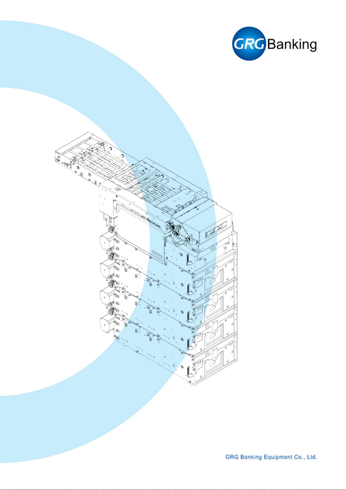
1 Note Feeder
YT4.029.039
CDM8240 Sevice manual(Level 2) Page 1 of 65

YT2.291.036WHSC-JX2
1.1 Tools
1.1.1 Standard service tools
Cross screwdriver
Slotted screwdriver
Long nose plier
Hexagonal screwdriver (M3, M4)
Force meter
1.1.2 Cleaning tools
Soft brush
Blower
Cloth
Alcohol
Grease lubricant
CDM8240 Sevice manual(Level 2) Page 2 of 65
YT2.291.036WHSC-JX2
1.2 Dismounting parts
1.2.1 Removing the note feeder
Refer to 《CDM8240Service Manual(Level 1)》 for the detailed operations on how to remove
the NF from CDM8240.
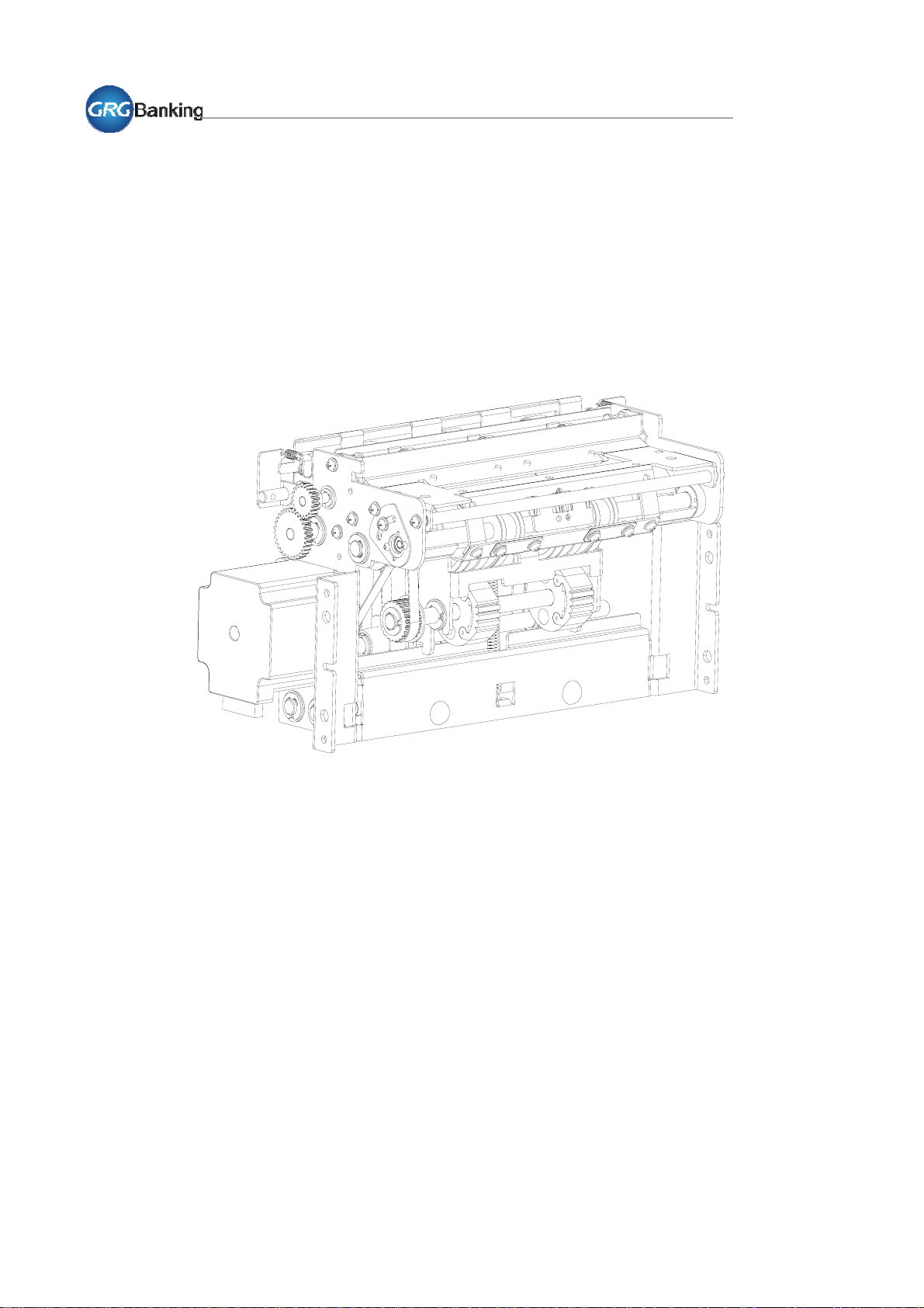
1.2.2 Removal of outter transport assembly
As is shown in the right picture,
remove the E rings and bearings
from the transport shaft, and then
remove 2 screws (combination
screw M3X8) from the short shaft.
Release the snap fits to unfold the
outer transport assembly, and take
it down.
Unfold
Short shaft
Outter transport
assembly
CDM8240 Sevice manual(Level 2) Page 3 of 65

YT2.291.036WHSC-JX2
1.2.3 Removal of localizer, eccentric cam and eccentric cam fork
Remove the screw (M3X6),
eccentric cam and eccentric cam
fork (be careful to protect the
one-way bearing from damage) on
right side of the separation roller
shaft.
Remove the localizers and CRR
eccentric cams on both sides of
counter rotating shaft (CRR shaft).
It is unnecessary to remove 2
screws (M2) securing the localizers
and eccentric cams.
Screws
Localizer
CRR eccentric cam Screws
Eccentric
cam
Eccentric
cam fork
1.2.4 Removal of counter rotating roller (CRR) assembly
Following the steps mentioned
above, remove the localizers,
eccentric cams and eccentric cam
fork.
And then remove 4 screws
(combination screw M3X6 and M3
X8, respectively) from the upper
fixing plate and top fixing shaft,
unfold the upper fixing plate, and
take down the CRR assembly.
Screws Fixing shaft
Screws
CRR
CDM8240 Sevice manual(Level 2) Page 4 of 65

YT2.291.036WHSC-JX2
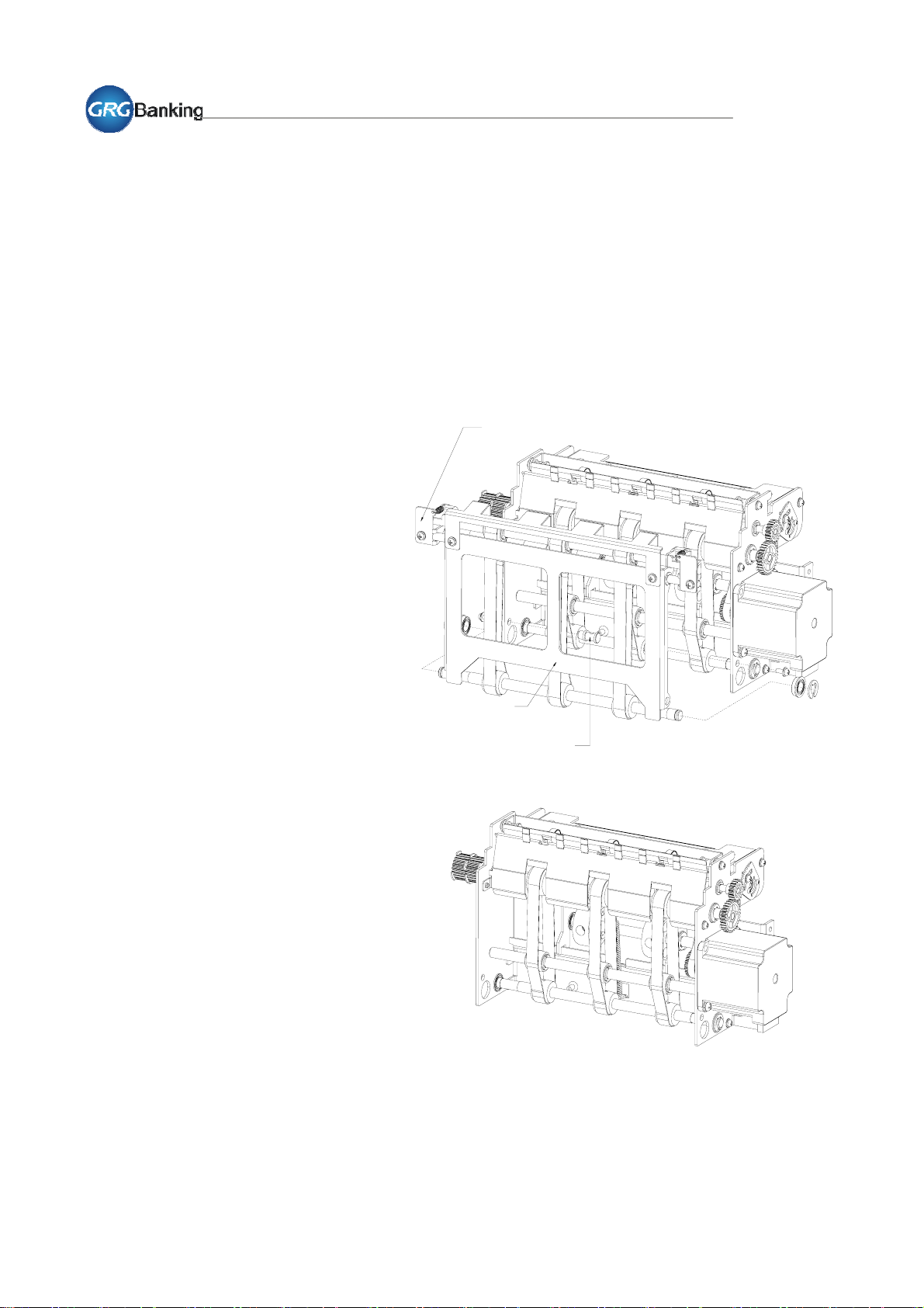
1.2.5 Removal of upper transport assembly
Following the steps mentioned
above, remove CRR assembly.
Remove 2 screws (combination
screw M3X8) from the short shafts
of upper transport assembly, and
then take down the upper transport
assembly.
Upper transport assembly
Short shafts
CDM8240 Sevice manual(Level 2) Page 5 of 65

YT2.291.036WHSC-JX2
1.2.6 Removal of lower transport assembly
Following the steps mentioned
above, remove upper transport
assembly.
Remove 2 screws (combination
screw M3X6 and M3X8,
respectively) on each side of the
lower transport assembly, and then
take down the lower transport
assembly.
Lower transport assembly
CDM8240 Sevice manual(Level 2) Page 6 of 65

YT2.291.036WHSC-JX2
1.2.7 Removal of pick motor
Remove 2 screws (combination
screw M4X10) and release the
timming belt from the pick motor
pulley then take down the motor.
Timing belt Pick motor
CDM8240 Sevice manual(Level 2) Page 7 of 65
YT2.291.036WHSC-JX2
1.2.8 Removal of pick and separate assembly
As is shown in the right picture.
Following the steps mentioned
above, remove upper and lower
transport assembly.
Using a long nose plier, remove the
Feeder spring, then remove c-clip
on the left, eccentric cam on the
right and bearings from the
separation roller shaft, take down
the pick and separate assembly.
Note: Please don’t remove the
timming belt in pick and separate
assembly.
Pick and separate assembly
Feeder spring
CDM8240 Sevice manual(Level 2) Page 8 of 65

YT2.291.036WHSC-JX2
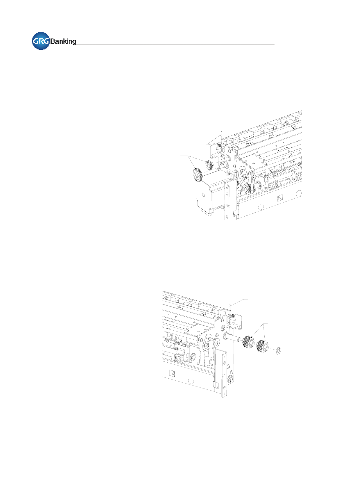
1.2.9 Removal of gear and timing pulley
Remove the fixing pins from the left
of acceleration roller shaft and
transport shaft to take down 2
gears.
Remove the timing pulley from the
right of transport shaft.
Pin
Gear
Pin
Timing Pulley
CDM8240 Sevice manual(Level 2) Page 9 of 65

YT2.291.036WHSC-JX2
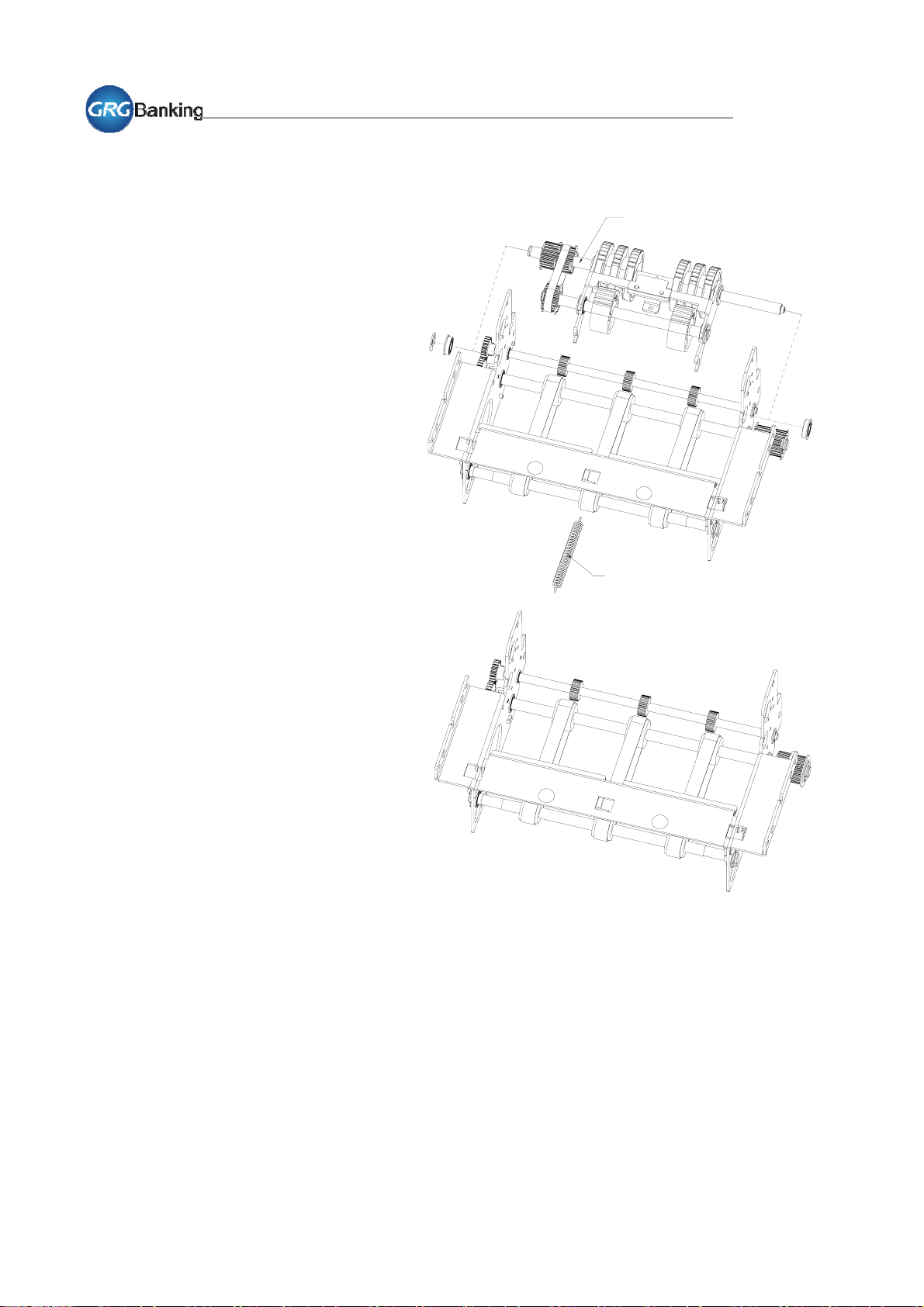
1.2.10 Removal of transport shaft assembly
Following the steps mentioned
above, remove upper and lower
transport assembly.
Remove the fixing screws from the
transport shaft (IM) to take down
the shaft, and then remove the E
rings and bearings from the
transport shaft (IU), acceleration
roller shaft and transport shaft (IL)
to take down the shafts and belts
(235mm). Transport shaft
(IL) assembly
Transport shaft
(IU) assembly Transport shaft
(IM) assembly
Accelaration Roller
Belt
(235mm)
CDM8240 Sevice manual(Level 2) Page 10 of 65
YT2.291.036WHSC-JX2
1.3 Replacing parts
1.3.1 Replacement of gear and timing pulley
Place the gear (teeth number=30)
onto the end of transport shaft (IU),
ensure the hole in the gear aligns
with the hole in the shaft, and then
push and glue the fixing pin into
the hole to fasten the gear using a
long nose plier.
Similarly, fit another gear (teeth
number=20) to the acceleration
roller shaft, make sure two gears
joggled with each other completely.
Note:Please make sure the fixing
pins are firmly fixed with glue and
prevent the pins from moving out.
Pin
Gear
Insert the fixing pin into the hole on
the right end of transport shaft (IU)
and place the timing pulley on the
shaft.
Fit c-clip in the groove on the shaft
to protect the pulleys from moving
out.
Pin
Timing pulley
CDM8240 Sevice manual(Level 2) Page 11 of 65
YT2.291.036WHSC-JX2
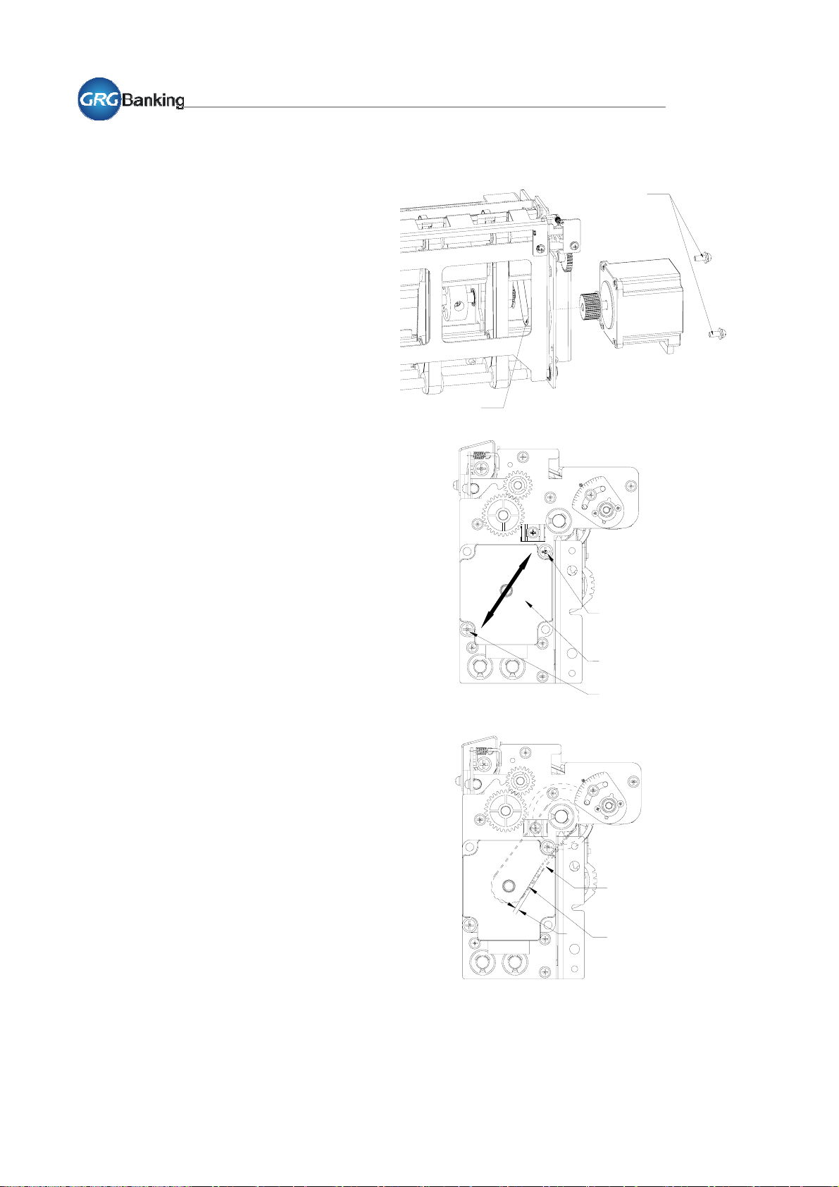
1.3.2 Replacement of pick motor
Fit the timing pulley to pick motor,
put the belt onto the timing pulley
while securing the pick motor onto
the left frame of note feeder by
tightening 2 screws (combination
screw M4X10).
Then follow the adjust instructions
to adjust the timming belt tension. Timing belt
Screws
Belt tension adjustment
Step 1: Release the 2 fixing screws
securing the pick motor.
Step 2: Move the pick motor in the
direction shown in right picture,
and make the belt tension
P=150±50gf while the belt
displacement A=1 mm.
Timing belt
P
Fixing Screw
Pick motor
Fixing Screw
A
CDM8240 Sevice manual(Level 2) Page 12 of 65

YT2.291.036WHSC-JX2
1.3.3 Replacement of CRR
Insert and make sure CRR shaft
ends into the holes on both sides of
note feeder frame, and then fit the
localizers and eccentric cams,
eccentric cam fork (be careful to
protect the one-way bearing from
damage) to the shaft.
Shut down the upper fixing plate to
proper position, and tighten 4 fixing
screws (combination screw M3X6
and M3X8, respectively).
Fit the eccentric cam to the
separation roller shaft and tighten
the fixing screw (screw M3X6).
Note: After replacement, please
follow the adjustment and test
instructions to adjust the gap.
CRR
Screws
Screws CRR
Fixing shaft
Eccentric
cam fork
CRR eccentric cam Screws
Eccentric
cam
Screws
Localizer
CDM8240 Sevice manual(Level 2) Page 13 of 65
YT2.291.036WHSC-JX2
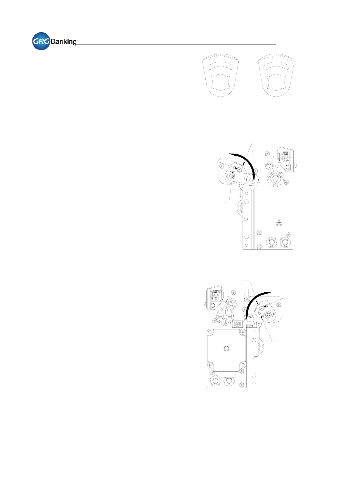
Gap adjustment
Step 1:
Loosen the screw on one side of NF frame.
Step 2:
Dial the Localizer to the very scale, and
make sure the scale is at the mark. Turn
localizer on the left clockwise and localizer
on the right counter-clockwise will make the
gap bigger. Otherwise, the gap will become
smaller.
Step 3:
Fasten the screw.
Step 4:
Following the Step 1 to Step 3 mentioned
above, adjust the scale on the other side. If
possible, the scales on both sides should be
same.
Note:Before and after the adjustment, it’s
strongly recommended that the scale should
be taken down as a record for recovery,
tracking and some other uses.
-8
0
+8
Right Side
0
-8
+8
Left Side
Localizer
Gap is bigger
To adjust the gap, loosen the screw,
dial the localizer to the very scale.
Screw
Mark
Mark Gap is bigger
Screw
Gap is smaller
Left Side
Gap is smaller
Localizer
Right Side
CDM8240 Sevice manual(Level 2) Page 14 of 65

YT2.291.036WHSC-JX2
Gap test
Step 1:
Follow the “Gap Adjustment” mentioned above to adjust the gap.
Step 2:
Use toolplus to test dispense, at least 1000 pcs note for each NF adjusted.
If reject too much notes, such as double note and long note, the gap should be adjusted to
decrease 1 or 2 scales.
If note is hard to be separated, such as skew note, damaged note and even jammed note, gap
should be adjusted to increase 1 or 2 scales.
Step 3:
Once adjusting the gap, “Gap Test” should be done to make sure note dispense is ok.
Note:During the maintenance, each time gap adjustment and test should be done if
pick-separate assembly or CRR is replaced. However, if just disassemble and assemble
pick-separate assembly or CRR without replacement, it’s necessary to adjust to the former
scale taken down as a record, and then follow the steps above to test.
CDM8240 Sevice manual(Level 2) Page 15 of 65
Table of contents
Popular Dispenser manuals by other brands


Welbilt
Welbilt Delfield NLFACP Original Instructions Installation, Operation and Maintenance Manual

SureShot
SureShot FlavorShot AC-FS10 Technical & service manual

SureShot
SureShot AC2-GP Operation manual

New Air
New Air Magic Chef Top Loading Water Dispenser manual

SureShot
SureShot AC2-GP-1-G38 Operation manual

Fillmaster Systems
Fillmaster Systems Auto user guide