Part Number: 9291482 04/22 9
Section 3 Operation
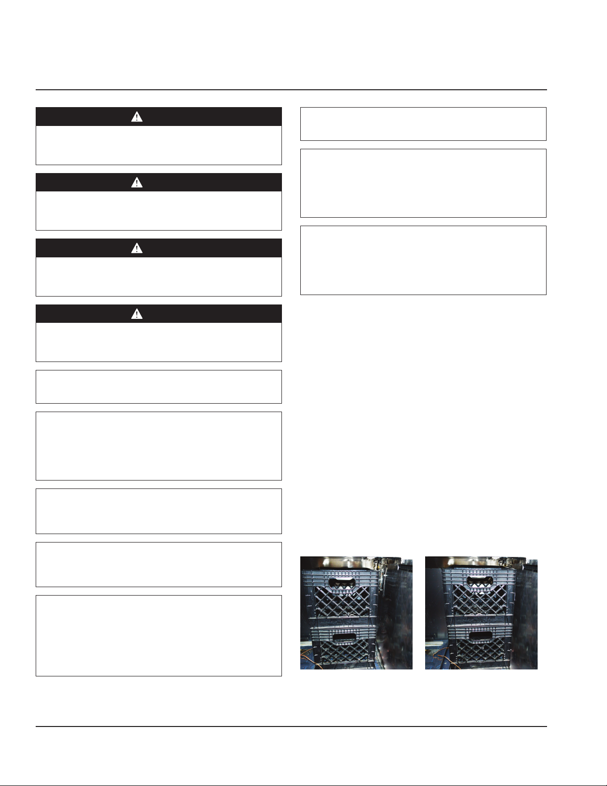
Lid Operation
Operating the unit for extended periods of time with the lid
open may result in product temperature change. For best
operation, leave the lid open no longer than 2 hours during
peak usage.
Evaporator Fan Operation
Depending on the units requirements, units may have
evaporator fans that run continually or cycle on and off when
power is applied. If you have a unit that you notice the fan is
cycling, please see the operations sequence below.
When the refrigerator is initially powered up or immediately
following a power outage the unit will begin cooling after a
3-6 minute delay. During normal operation the evaporator
fan pulses independently of the compressor as dictated by
the controller as follows:
1. During the cooling mode, compressor and evaporator
fan run simultaneously.
2. During the compressor off mode, evaporator fan pulses
three minutes on and three minutes off.
3. During an actual defrost event other than the off-cycle
defrost, compressor stays off but the evaporator fan
runs continuously.
Cooling Cycle Defrost Cycle
Compressor On Compressor Off Compressor Off
Evaporator Fan On Evap Fan Cycles On
3-Min, Off 3-Min
Evaporator Fan On
CONTROLS
At Start Up
1. At initial start-up or anytime power is disconnected, then
reconnected to the unit, the control will go into defrost
mode.
2. The control will enter a DEFROST mode and the display
will read dEF. The compressor and condenser fan as well
as the evaporator fan will remain off until this initial
defrost is complete. This initial defrost cycle may take up
to 35 minutes to complete.
3. The display will continue to read dEF for an additional 30
minutes while the cooling cycle cools the box to the set
temperature.
4. Then the digital thermostat will display box temperature.
Normal operation setpoint is 36°F.
5. The temperature control will cycle the compressor,
evaporator fan motor and condenser fan motor to
maintain box temperature at the control setting. For more
information see Evaporator Fan Operation on page 9.
Defrost
The temperature control also monitors the evaporator
temperature and will turn off the compressor and condenser
fan motor when needed to allow accumulated frost on the
evaporator to clear. During this defrost cycle, the digital
temperature display will read dEF. After the defrost cycle is
complete, the temperature control will return to a normal
cooling cycle, but the display will continue to read dEF until
the evaporator returns to normal cooling temperatures (up
to 30 minutes).
The electronic temperature controller monitors evaporator
temperature and compressor run time to determine the
proper time for a positive defrost cycle. A defrost cycle can
occur as often as every 2 hours under extremely heavy
usage. It can last a minimum of 2 minutes. When the
controller enters the defrost mode the compressor is shut
off and will remain off until the evaporator coil temperature
exceeds:
• 41°F (5°C) or the controller reaches a time limit of 100
minutes on a refrigerated unit.
ERC112 TEMPERATURE CONTROL
Status Displayed Comments
Normal (°C) Temp. [°C] Unit depends on setting
(parameters in control)
Normal (°F) Temp. [°F]
Show set-point Temp.
Set to Defrost dEF / Temp Depends on setting
(parameters in control
or as chosen by upper
left button)
Sensor 1 defect E01 X Air sensor
Sensor 2 defect E02 X Coil sensor
Sensor 3 defect E03 X Open
Sensor 4 defect E04 X Open
High temperature alarm Hi X Automatically switching
at 2 sec rate
Low temperature alarm Lo X
Line voltage too high,
above 140 volts
uHi X
Line voltage too low,
below 96 volts
uLi X
Control calls for cooling
for more than 24 hours
straight
LEA X Time includes defrost.
Error will go away if the
control cycles off the
compressor or if the
power is shut off. If error
is on a cold pan it could
be related to a high
ambient temperature or
not shutting the rail off
nightly.
All alarms sound for approximately 10 seconds and then