Cristec RCE/100 – 2E – 3IG User manual
RCE
Nederlands Gebruikershandleiding
Product beschrijving
De Battery Isolator is een elektronische laadstroomverdeler die op zeer betrouwbare wijze dient voor
het gelijktijdig en verliesarm laden van meerdere accugroepen van dezelfde nominale spanning.
De
Battery Isolator beïnvloed de gunstige laadkarakteristiek van de aange
sloten lader en/of dynamo
niet, zodat de accu's direct met de juiste 'boostspanning' worden opgeladen. Er hoeft daarom geen
spanningscompensatie worden uitgevoerd, zoals bij conven
tionele scheidingsdiodes Door
toepassing van de Battery Isolator wordt voorkomen dat de accugroepen elkaar kunnen ontladen. De
Battery Isolator is uitsluitend geschikt voor in
stallatie tussen de positieve uitgang van de acculader
en/of dynamo en de positieve aanslui
tingen van de beide accugroepen. Hierbij dienen de negatieve
uitgang van de accula
der/dynamo en de negatieve aansluitingen van de accugroepen direct met
elkaar te worden
doorverbonden. Kostbare accuschakelaars en lasse onderhoudsladers op
iedere accuset
zijn hierdoor overbodig geworden
Installatie
Overtuig uzelf ervan dat de uitgang van de acculader/dynamo spanningsloos is gedurende de
installatiewerkzaamheden. Verbreek hiertoe aile elektrische verbindingen met de accula
der/dynamo
en de ac
cu's. Zorg er tevens voor dat er geen gebruikers zijn aangesloten op de accugroepen ter
voorkoming van onveilige situaties. Monteer de Battery Isolator zo dicht mogelijk bij zowel de
acculader/dynamo ais bij de accugroepen, maar nooit direct boven een accu
i.v.m. mogelijke
corrosieve accudampen. De Battery Isolator kan warm worden ais ge
volg van grote stromen.
Installeer de Battery Isolator daarom op een goed geventileerde plaats, bij voorkeur op een vlakke
metalen ondergrond (nooit op de hoofdmotor), met de koelribben verticaal geplaatst.
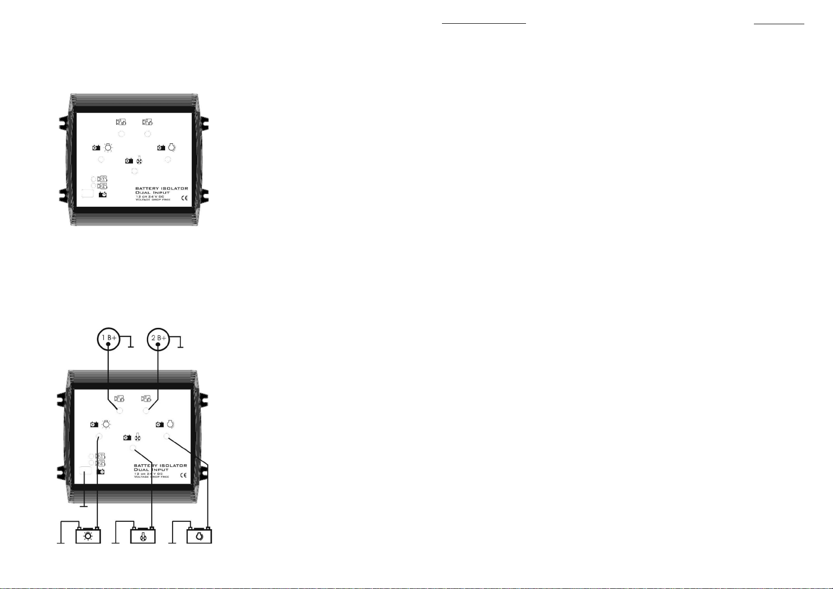
Zie tekening voor de juiste wijze van aansluiten. Monteer de negatieve aansluitingen van de
accugroepen en de acculader/dynamo op een gemeenschappelijk massapunt. De groene LED aan
de bovenzijde van de Battery Isolator licht op wanneer er spanning op de ingang van de Battery
Isolator staat. De Battery Isolator detecteert automatisch de nominale laadspanning (12V of 24V). ln
tegenstelling tot conventionele scheidingsdiodes is er bij de Battery Isolator nauwelijks sprake van
spanningsverlies. Bij gebruik van de Battery Isolator dient de uitgangsspanning van voedingsbron
daarom NIET te worden verhoogd voor diodecompen satie. Ais de lader accuspanning moet
"proeven" alvorens te gaan laden, dan is deze vaak uitgevoerd met een z.g.n. sense-ingang.
Gebruikers handleiding,
Operation manual,
Betriebsanleitung,
Mode d'emploi
Veiligheidsvoorschriften en
-
maatregelen
1. Installeer de Battery Isolator vol gens bovengenoemde instructies
2. Gebruik de Battery Isolator nooit op een locatie met gas- of stofontploffingsgevaar.
3.Aansluitingen en beveiligingen moeten in overeenstemming met de plaatselijk geldende
voorschriften worden uitgevoerd.
4. Gebruik kabels met voldoende draaddoorsnee en houd aile afstanden zo kart mogelijk. Gebruik
deugdelijke kabelschoenen en draai aile aansluitmoeren goed aan.
Aansprakelijkheid
Fabrikant kan niet aansprakelijk worden gesteld voor:
•Schade ontstaan door het gebruik van de Battery Isolator
•Eventuele fouten in bijbehorende handleiding en de gevolgen daarvan
•Ander gebruik geldend ais niet conform de bestemming van het product
Garantiebepalingen
Fabrikant garandeert dat de Battery Isolator is geproduceerd volgens de wettelijk van toe
passing
zijnde normen en bepalingen. Gedurende de productie en vo
or aflevering zijn aile Battery Isolators
uitvoerig getest en gecontroleerd. Wanneer niet volgens de in deze hand
leiding gegeven
voorschriften, aanwijzingen en bepalingen wordt gehandeld, kunnen be
schadigingen ontstaan en/of
het apparaat zal niet aan de specificaties voldoen. Een en an
der kan inhouden dat de garantie komt
te vervallen. De garantietermijn is twee jaar.
Type
Number of inputs
Number of outputs
Max current
System voltage
Input voltage range
Insulation to ground
Operating temperature
Voltage drop
Dimensions (l x h x d)
Weight
RCE/100 -2E – 3IG
3
100
12 -24 VDC
8 - 30 VDC
>500V@50 HZ
-40 to +85 'C
0.0V@10A / 0.1V@20A
146x85x 158 mm
1115 g
LI
GHT
BO
W
PROP
START
06-06-2007
2
RCE
English User Manual
Product descriptio
n
The Manufacturer Battery Isolator is an electronic device which is designed to distribute the charg
e
current with a low voltage dro
p between several (sets of) batteries with the same nominal voltage.
The Battery Isolator prevents the current from flowing from one battery to
another. The Battery
Isolator can only be installed in the positive lead between the supplying source (for instance a
charger or an alternator) and the batteries. Therefore the negative output of the supplying source
should be connected directly to
the negative connections of the battery sets. The Battery Isolator has
no voltage dro
p when the batteries are fully charged. This is achieved by using the latest electronic
technologies, other diode splitters have at least a voltage drop of 0,7 Volt and at a high c
harging
current this voltage drop can reach 1,5 Volt. The voltage dro
p of the Battery Isolator will never
exceed 0,4 Volt at max amperage. At a charging current of 20 Amps. per battery, the voltage dro
p is
negligible. The Battery Is
olator has therefore no influence on the charging characteristics of the
charger or the alternator. Diode compensation is not required to be ab
le to charge the batteries up to
100%
Installation
Be sure that the output of the supplying source is switched
off during installation. Disconnect ail
electrical connections to the charger/ alternator and the batteries. Also be sure th
at no consumers
are connected to the batteries during installation, to prevent hazardous situa
tions. Install the Battery
Isolator not only as close as possible to the supplying source, but to the batteries as well
, but do not
install The Battery Isolator straight above the batteries be
cause of possible corrosive sulphur fumes.
The Battery Isolator must be installed in a well ventila
ted environment, as high currents will heat up
the Battery Isolator. Preferably, the battery isolator should be mounted on a flat
metal surface (never
directly to the main engine), with the fins vertical.
For correct connection see drawing. Connect the n
egative pales of the battery sets and the supplying
source to a common ground. When DC-
power is available from the Battery charger / Alternator, the
green LED on top of the Battery Isolator illuminates
The Battery Isolator automatically detects the nominal charge voltage (12V or 24V). Unlike
convention al battery isolators, the Battery Isolator is almost free of voltage drops. Therefore, when
the Battery Isolator is applied, the output voltage of the supplying source should NOT be increased
for diode compensation. No internal or external settings are required.
Safety regulations and measures
1. Install the Battery Isolator according to the stated instructions.
2.Never use the Battery Isolator at a location where there is danger of gas or dust explosions.
3. Connections and safety features must be executed according to the locally applicable regulations.
4. Use cables with appropriate size wire and keep the cable connections as short as possible. Use
reliable terminals and fasten the bolts tightly, but do not over torque.
Liability
Manufacturer cannot be held liable for:
•Damage resulting from the use of the Battery Isolator.
•Possible errors in the included manual and the consequences of these.
Guarantee terms
Manufacturer guarantees that the Battery Isolator has been built according to the legally ap
plicable
standards and stipulations. During production and before delivery ail Battery Isola
tors were
exhaustively tested and contra lied. If you fail to act in accordance with the regulations, instructio
ns
and stipulations of this user's manual, damage can occur and/or the unit will not fulfil the
specifications. This may mean that the guarantee will become null and void. The guarantee period is
2 years.
Type
Number of inputs
Number of outputs
Max current
System voltage
Input voltage range
Insulation to ground
Operating temperature
Voltage drop
Dimensions (l x h x d)
Weight
RCE/100 -2E – 3IG
3
100
12 -24 VDC
8 - 30 VDC
>500V@50 HZ
-40 to +85 'C
0.0V@10A / 0.1V@20A
146x85x 158 mm
1115 g
06-06-2007
3
1
RCE/100 – 2E – 3IG
For 12 and 24 VDC systems
Voltage drop free

RCE/100 -2E – 3IG
3
100
12 -24 VDC
8 - 30 VDC
>500V@50 HZ
-40 to +85 'C
0.0V@10A / 0.1V@20A
146x85x 158 mm
1115 g
RCE
Deutsch Betriebsanleitung
Produkt beschreibung
Der Sattery Isolator ist sin elektronischer Ladeverteiler zur gleichzeitigen und verlustarmen Verteilung
des Ladestroms zwischen mehreren Batteriesatzen der gleichen nominalen Spannung. Der Einsatz
des Sattery Isolator sorgt dafür, dass sich die Batteriesatze nicht ge
genseitig entladen. Der Battery
Isolator ist ausschliel3lich geeignet für eine Montage zwischen dem Plus-
Ausgang eines
Stromerregers (Ladegerat oder Lichtmaschine) und dem Plus-
Anschluss der Batteriesatze. Der
Minusausgang des Stromerregers und die Minus
Anschlüsse der Batteriesatze müssen direkt mit
einander verbunden werden.
Installation
Stellen Sie sicher, dass der Stromerreger wahrend der Installation spannungsfrei ist Tren
nen Sie aile
elektrischen Verbindungen vo
n dem Ladegerat / der Lichtmaschine und den Batterien. Es ist
ebenfalls wichtig dass, keine Verbraucher an den Batteriesatzen ange
schlossen sind. Montieren Sie
den Battery Isolator mëglichst nah an den Stromerreger und ebenfalls mëglichst nah an die
Batteriesatze,
aber niemals direkt oberhalb der Batterien, wegen moglicher korrosiver
Batteriedampfe. Der Battery Isolator kann durch die hohen Strome sehr warm werden. Installieren
Sie deswegen den Battery Isolator in einem gut belülteten Raum, vorzugsweise a
uf einem flachen
Metall-
Untergrund (aber nie direkt auf dem Motor) und mit senkrecht angeordneten Kühlrippen. Für
die richtige Anschlussweise siehe Zeichnung. Verbinden Sie die Minus-
Anschlüsse der Batteriesatze
und den Stromerreger mit einem gemeinsamen
Massepunkt Wenn Spannung von dem Akkulader /
der Lichtmaschine zur Verfügung steht, leuchtet die grüne LED an der Oberseite des Battery Isolator
auf. Die Battery Isolator entdeckt die nominale Ladespannung (12 oder 24V) automatisch. ln Gegen-
satz zu den konventionellen Trenndioden kommt es bei dem Battery Isolator kaum zu Span-
nungsverlusten. Deswegen brauchen Sie die Ausgangsspannung des Stromerregers NICHT zur
Diodenkompensation erhohen.
Sicherheitsvorschriften und
-
maBnahmen
1. Installieren Sie den Battery Isolator gema~ den genannten Anweisungen.
2.Benutzen Sie den Battery Isolator nie in einer Umgebung, in der die Gefahr einer Gasoder
Staubexplosion besteht.
3. Anschlüsse und Sicherheitsvorkehrungen müssen den lokalen Vorschrilten entsprechend
ausgeführt werden.
4. Benutzen Sie Kabel mit geeignetem Querschnitt und halten Sie die Lange moglich kurz. Benutzen
Sie zuverlassige Kabelverbinder und drehen Sie aile Verbindungen fest.
Haftung
Fabrikante haltet nicht für:
1. Durch die Benutzung des Battery Isolator entstandene Schèden.
2. Mëgliche Fehler in der mitgelieferten Anleitung und die daraus entstehenden Foigen.
3.Einen anderen Gebrauch, d.h. einen Gebrauch, der nicht mit der Bestimmung des Produkts
übereinstimmt.
Garantiebestimmungen
Fabrikante garanti
ert, dass der Battery Isolator unter Einhaltung der gesetzlichen Normen und
Bestimmungen gebaut wurde. Bei der Herstellung und vor der Lieferung werden aile Battery Isolators
weitgehend getestet und kontrolliert. Wenn die in dieser Gebrauchsanlei
tung besc
hriebenen
Vorschriften, Anweisungen und Bestimmungen nicht beachtet werden, kënnen Schèden entstehen
und/oder kann das Gerat nicht den Spezifikationen entsprechen. Das bedeutet, dass keine Garantie
mehr geleistet werden kann. Die Garantiezeit betragt 2 Jahre
Type
Number of inputs
Number of outputs
Max current
System voltage
Input voltage range
Insulation to ground
Operating temperature
Voltage drop
Dimensions (l x h x d)
Weight
RCE/100 -2E – 3IG
3
100
12 -24 VDC
8 - 30 VDC
>500V@50 HZ
-40 to +85 'C
0.0V@10A / 0.1V@20A
146x85x 158 mm
1115 g
06
-
06
-
2007
RCE
Français Mode d'emploi
Description
Le Battery Isolator est un répartiteur électronique conçu pour distribuer le courant de charge avec
une faible chute de tension entre différent
es batteries ou parcs de batteries avec la même tension
nominale. Le Battery Isolator empêche le courant de circuler d'une batterie
à
une autre. Le Battery
Isolator peut être installé seulement entre le pôle positif de la source de courant (par exemple un
chargeur ou un alternateur) et les batteries. Le pôle négatif de la source de courant doit être
connecté au pôle négatif des batteries.
Installation
S'assurer que la sortie de la source de courant est arrêtée pendant l'installation. Débrancher toutes
les
connexions électriques au chargeur / alternateur et aux batteries. Vérifier qu'aucun appareil n'est
connecté aux batteries, afin d'éviter toute situation dangereuse. Installer
le Battery Isolator très près
de la source de courant et également très près des batteries, mais jamais au-
dessus des batteries,
à
cause de possible dégagements
corrosifs de soufre. Il doit être installé dans un endroit bien
ventilé, en effet les courants élevés augmentent
la température du Battery Isolator. Si possible, il
doit être installé sur une surface en métal
plate (jamais directement sur le moteur), les lamelles
verticales. Pour une connexion correcte
, se reporter au schéma. Connecter les pôles négatifs de la
batterie et de la source de courant
à
la masse. Lorsque la tension
du chargeur / alternateur est
disponible, le voyant vert s'allume. Le Battery Isolator détecte automatiquement la tension nominale
de charge (12V ou 24V). Contrairement aux répartiteurs de charge
à
diodes traditionnels, le Battery
Isolator ne provoque qu'une très faible chute de tension. Par conséquent, la tension de sortie
de la
source de charge NE doit PAS être augmentée.
Consignes et mesures de sécurité
1. Installer le Battery Isolator conformément aux instructions.
2.Ne jamais utiliser le Battery Isolator
à
un endroit comportant un risque d'explosion de gaz ou de
poussière.
3. Les raccordements et sécurisations doivent être effectués conformément
à
la réglementation
locale.
4. Utiliser des câbles de section appropriée aussi courts que possibles. Utiliser des cosses et serrer
bien les écrous, mais ne pas les forcer.
Responsabilité
Le fabricant décline toute responsabilité dans les cas suivants
1. Dommage survenu suite
à
l'emploi du Battery Isolator.
2. Eventuelles erreurs dans le manuel correspondant et leurs conséquences
3. Autre utilisation considérée comme non conforme
à
la destination du produit
Conditions de garantie
Le fabricant certifie que le Battery Isolator est fabriqué conformément aux normes et dispositions
légales en vigueur. Tous les Battery Iso
lators sont minutieusement testés et contrôlés pendant leur
production et avant leur livraison. L'utilisation non conforme aux consignes, instructions et
dispositions fournies dans ce manuel d'utilisation peut entraîner des dommages et/ou l'appareil ne
répondra pas aux spécifications. Ce qui peut donner lieu
à
l'annulation de la garantie. Le délai de
garantie est de 2 ans
Type
Number of inputs
Number of outputs
Max current
System voltage
Input voltage range
Insulation to ground
Operating temperature
Voltage drop
Dimensions (l x h x d)
Weight
4
06
-
06
-
2007
5
Other Cristec Media Converter manuals


Popular Media Converter manuals by other brands


Enterasys
Enterasys VHIM1000-S1GM Quick installation guide

AJA
AJA ROI Installation & operation guide

HEIDENHAIN
HEIDENHAIN ERO 6070 Mounting instructions

Niveo Professional
Niveo Professional NMC220 Series Quick installation guide

CYP
CYP CLUX-SDI2HS Operation manual

Extron electronics
Extron electronics NAV E 501 Setup guide


