Cristec 12V / 10A User manual

CPS-UNIT-DAA 30016653
Documentation
C.P.S. Power unit
Range
12V / 10A
12V / 16A
12V / 25A
S.A.S CRISTEC
31, rue Marcel Paul - Z.I. Kerdroniou Est
29000 QUIMPER FRANCE
Tél : 33 (0)2.98.53.80.82 Fax : 33 (0)2.98.55.64.94
e-mail : info@cristec.fr http://www.cristec.fr

CRISTEC
CPS-UNIT-DAA Page 2
Operating Manual in English Page 3
WARRANTY CARD Page 22
Do not forget to fill in the warranty card and
send it back to us.

CRISTEC
CPS-UNIT-DAA Page 3
CONTENTS
DESCRIPTION PAGE
Contents 3
nIntroduction 4
1.1 Installation and operating manual 4
1.2 Validity of this document 4
1.3 Guarantee 4
1.4 Brief presentation 4
Installation and connection diagram 5
1.5 Reference standards applied 6
oCharacteristics and operation 7
2.1 Technical characteristics 7
2.2 Charger operation 10
pInstallation 12
3.1 Introduction 12
3.2 Items supplied 12
3.3 Additional supplies necessary for electrical installation 12
3.4 Special recommendations for installation 14
3.5 Commissioning 16
qMaintenance and repair of equipment 17
4.1 Introduction 17
4.2 Equipment maintenance 17
4.3 Equipment repair 17
rSafety 18
5.1 Standards references 18
5.2 Precautions relating to personnel safety 18
5.3 Precautions relating to protection against fire and explosion 18
sAppendice 19

CRISTEC
CPS-UNIT-DAA Page 4
nIntroduction
1.1 Installation and operating manual
The present document applies to power unit in the CRISTEC CPS range of power
units listed below.
Power (Watts) U/I Rating CRISTEC Reference
120 12/10 SEEL006685
190 12/16 SEEL006686
300 12/25 SEEL006687
This manual is intended for users, installers and equipment maintenance personnel
who must ensure they understand the present document before any intervention on
the power unit.
1.2 Validity of this document
This document is the property of CRISTEC; all the information contained in this
document applies to the accompanying product. The company reserves the right to
modify the specifications without prior notice.
1.3 Guarantee
Failure to comply with the rules for installation and operation cancels the
manufacturer's guarantee and absolves CRISTEC of all responsibility.
The period of guarantee is 36 months. It applies to parts and labour for an
equipment returned to the factory. Only parts acknowledged to have been
defective from the outset will be replaced under the guarantee.
Equipment which has been misused or damaged by errors in connections, impacts,
falls or which is defective from having been worked upon by persons other than those
authorized by CRISTEC Industries.
Equipment which has been installed or operated at variance with procedures outlined
in the manual provided with each unit.
Under no circumstances, can any indemnity be granted by this warranty.
This warranty does not apply to the following terms :
nTransportation and packaging charges to and from the factory or authorized
service station.
oDamage sustained in shipment, apparent or concealed.
Claims for such damage must be reported and filed with the carrier by the person
receiving the equipment.

CRISTEC
CPS-UNIT-DAA Page 5
1.4 Brief presentation
Designed in partnership with the main French boat builders, the CRISTEC power
units allow to get in a single cabinet the on-board 230VAC protection and a battery
charger.
The power housings meet the European on-going rules. Compact and lightweight,
they provide practical entry for the cabling that reduces mounting time.
The 230VAC user protection is insured by a 16A/30mA differential circuit breaker.
The 230VAC on-board utilisation outputs are protected by 2 off 10 DPN thermo-
magnetic circuit breakers.
The charger function is made by a switch mode charger PCB from our classic CPS
charger range : Selective Programmable Charge.
General characteristics :
- Input voltage : 115 or 230VAC +/-15%
- Input frequency : from 47 to 63 Hz
- Display : green LED for mains present
- Input and output cabling on gland
- Functioning temperature : 0°C/+40°C
- Matt black RAL 9011 and grey RAL 7035, salt atmosphere resistant
- CE standards: EN50081-1, EN50082-1, EN 55011, EN55022, EN60950 & ISO 13297
Charger characteristics :
- Input voltage : 115 or 230VAC +/-15% by internal switch
- Output voltage : 12VDC +/-1%
- Three automatic charge cycles : boost, absorption, floating
- Six hours programmable timed boost by internal switch
¾Position "BOOST ON" for authorize boost
¾Position "BOOST OFF" for inhibit boost
- Charge distributor incorporated into each battery output
- Specific output matched to the engine battery charging on 16A and 25A models
- Selection of the level of charge according to the type of battery by internal switch
¾Plomb/Antimoine (ANT)
¾Plomb/Calcium (CAL)
- Internal potentiometer allows output voltage to be adjusted
- Protection against shorts-circuits and polarity reversal. Fuses on input and output.
- Low noise, thermostatically controlled electric fan on 25A model

CRISTEC
CPS-UNIT-DAA Page 6
Characteristics distribution AC :
- General input protection by a 30mA / 16A differential circuit breaker.
- AC outputs : protected by 2 thermo-magnetic circuit breaker DPN 10A.
ÂWhen they leave the factory the chargers are configured as follows :
¾Mains supply: 230 Vac
¾Battery: Lead/Antimony
¾Charging mode : Boost then automatic switch to Floating
¾Output voltage setting in Floating:
at 13.8 V ±1% off load
ÂCable entry is via cable glands.
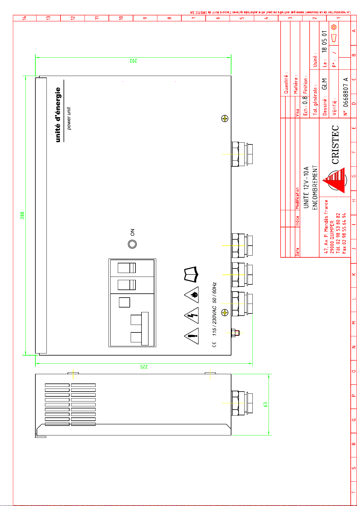
ÂDimensions drawing : see appendice.
ÂTerminal drawing : see appendice.
ÂFixing drawing : see appendice.
ÂSetting charger board drawing : see appendice.
1.5 Reference standards applied
The standards applied are:
¾NF EN 60950 + A1 + A2 (October 93): safety of information processing
equipment including electrical office
equipment.
¾NF EN 50081-1 (June 92) EMC: Generic standard for emissions
¾NF EN 50082-1 (June 92) EMC: Generic standard for immunity
¾NF EN 55022 (December 1994): Limits and methods for measuring the
characteristics of RF interference
produced by information processing
equipment.
Enacted at Quimper on: 2 March 2000 For and on behalf of CRISTEC SA,

CRISTEC
CPS-UNIT-DAA Page 7
oCharacteristics and operation
2.1 Technical characteristics
2.1.1 Mechanical characteristics
All models have an IP 21 protection rating. The are made of steel or of aluminium.
These parts are protected by several coats of epoxy paint.
Overall dimensions and weights of the various models are specified in the table
below :
Model Length (mm) Height (mm) Depth (mm) Weight (kg)
12V / 10A 290 220 75 3.2
12V / 16A 345 220 110 4.4
12V / 25A 345 220 110 4.4
Dimensions and fixing drawing : see appendice.
2.1.2 Input characteristics of charger
Model
Permissible
input
voltage
(Vac)
Permissible
input
frequency
(Hz)
Typical input
current rating
at 115 Vac
Typical input
current rating
at 230 Vac
Fuse
rating
and
format
12V / 10A 3A 1.5A 3.15A T
5 x 20
12V / 16A 4A 2A 10 A T
6.3 x 32
12V / 25A
115 Vac
+/- 15% or
230 Vac
+/- 15%
single phase
by manual
selection
47 to 63 Hz
6A 3.3A
10 A T
6.3 x 32
2.1.3 Output characteristics of charger
2.1.3.1 Output voltage of charger
The output voltages shown in the table below are obtained at 10% of rated power on
outputs BAT 1 and BAT 2. For those models having a BAT D output, the voltage
level is reduced by about 0.4 V.

CRISTEC
CPS-UNIT-DAA Page 8
These values are set in the factory with an accuracy of ±1% and can be adjusted by
turning the potentiometer POT U (use a suitable tool for turning the potentiometer
screw).
They depend on the type of battery and mode of operation selected.
Model
Lead/Antimony
Battery
"Floating" Mode
Lead/Antimony
Battery
"Boost" Mode
Lead/Calcium
Battery
"Floating" Mode
Lead/Calcium
Battery
"Boost" Mode
12V / 10A
12V / 16A
12V / 25A
13.8 Vdc 14.5 Vdc 14.6 Vdc 15,4 Vdc
2.1.3.2 Output current of charger
The table below defines the maximum output current at rated output power as well
as the type and rating of the fuses placed in series with the charger outputs.
Model Maximum output
current Fuse rating Type of fuse
12V / 10A 10 A 15 A 257015 LITTLEFUSE
12V / 16A 16 A 20 A 257020 LITTLEFUSE
12V / 25A 25 A 25 A 257025 LITTLEFUSE
2.1.4 Environmental specification
All chargers in the range meet the following characteristics:
¾Storage temperature: - 20°C to + 70°C.
¾Operating temperature: 0°C to + 40°C.
¾Humidity: < 90% non-condensing
2.1.5 Protection and operating safety of charger
2.1.5.1 Input protection
Models 12V / 10A, 12V / 16A, 12V / 25A are fitted with two pole protection by 2
fuses F1 and F2 whose ratings are given in section 2.1.2.
2.1.5.2 Output protection
Output protection is provided by a fuse placed in series with the "–" terminal of the
charger. The rating and type of this fuse are defined in the table in section 2.1.3.2.
CRISTEC
CPS-UNIT-DAA Page 9
2.1.5.3 Additional safety devices
All models are fitted with the following safety devices:
¾Protection against input voltage surges by a Varistor (275 Vac).
¾Protection against abnormal heating of the power semiconductors.
¾Protection against polarity reversal (output fuse blows)
¾Protection against overloads on the output by limiting the power to the rated
value for each model.
2.1.6 Options
The options do not form part of the basic power unit supply. They are available
from your reseller or from CRISTEC's Sales Department.
zAnalogue voltmeter for displaying the charging voltage at the input side of
the charge distribution diodes.
Model Rated output
voltage (V) Voltmeter reference
Charger 12V 12 V VLT 0012
zAnalogue ammeter for displaying the total battery charging current
Model Maximum output
current
Ammeter reference
12V / 10A 10 A AMP 0120/1
12V / 16A 16 A AMP 0190/1
12V / 25A 25 A AMP 0300/1
zBattery temperature compensation*
Probe length Probe reference
1 m STEMP/1
3 m STEMP/3
* : Except for models 12V / 10A.
CRISTEC
CPS-UNIT-DAA Page 10
2.2 Charger operation
2.2.1. Output voltage
The charger delivers a voltage suitable for recharging 1, 2 or 3 separate batteries.
All models (12V / 10A) are fitted with an output suitable for recharging the engine
battery (BAT D output). Nevertheless, for chargers 12V / 10A, you can use one of
the outputs for recharging engine battery.
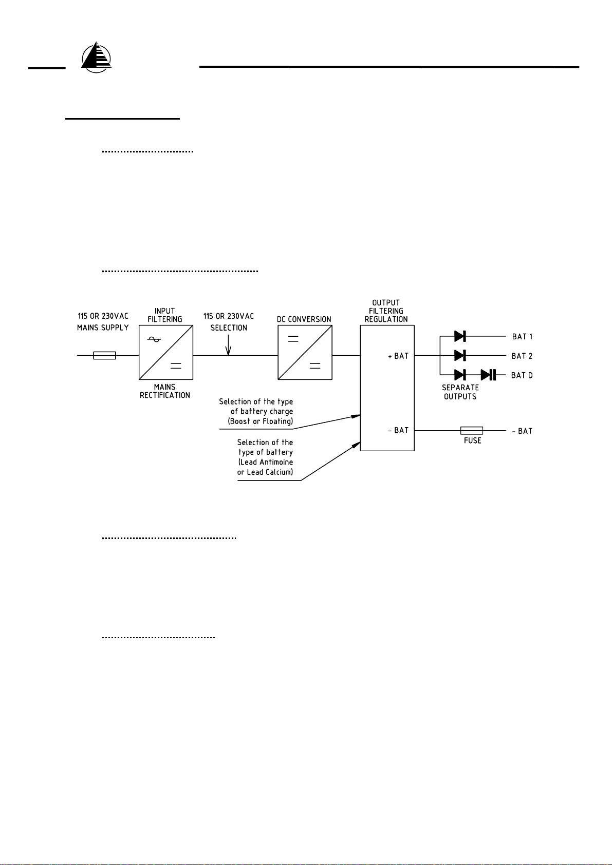
2.2.2. Block diagram of charger
2.2.3. Principle of operation
The CPS range of battery chargers are designed on the basis of a high frequency
switching converter which transforms the ac signal into a regulated, filtered dc
voltage suitable for charging accumulator batteries.
2.2.4. Detailed operation
After the initial selection of input mains, type of battery and type of charge, battery
charger operation is entirely automatic.
2.2.4.1 Selector operation
zMains voltage selector
The charger is fitted with an internal voltage selector enabling it to operate on 2
types of mains supply :
ÂEuropean mains supply: 230 Vac – 50/60 Hz
ÂOther mains supplies (USA, etc. …): 115 Vac – 50/60 Hz

CRISTEC
CPS-UNIT-DAA Page 11
zBattery type selector
The charger is fitted with an internal selector enabling it to operate on 2 types of
battery just by changing a switch:
ÂLead/Antimony battery: "ANT"
ÂLead/Calcium battery: "CAL"
zCharge type selector
The charger is fitted with an internal selector enabling it to provide 2 types of
charging just by changing a switch:
ÂCharge in Floating mode: "BOOST OFF"
ÂCharge in Boost mode for 6 hours ±30 minutes then automatic switch to
Floating mode: "BOOST ON"
NB: The Boost voltage off load is about 5% higher than the off load Floating
mode voltage.
2.2.4.2 Operation of the indicators
This indicator is fitted on the charger front panel and displays the unit's mode of
functioning. Differential circuit breaker ON.
z"Mains present" indicator
This indicator is extinguished in the following circumstances:
ÂAbsence or degradation of the ac mains supply,
ÂDifferential circuit breaker OFF or triped.
2.2.4.3 Special operation
zSpecial batteries
The factory settings are for standard use of Lead/Antimony and Lead/Calcium
batteries. Refer to a professional installer for special settings to match the battery
manufacturer's specifications, taking into account the special features of the
installation.

CRISTEC
CPS-UNIT-DAA Page 12
zElectricity generating sets
The CRISTEC battery charger is designed for use from an electricity generating
set.
In certain circumstances, electricity generating sets can generate large
overvoltages. Before connecting the charger, check that the charger is compatible
with the generator: power, voltage, voltage surges, frequency, current, …
pInstallation
3.1 Introduction
This section deals with matters relating to charger installation.
Installation and operating the charger for the first time must be undertaken by an
electrician or professional installer in accordance with the standards in force (in the
case of pleasure boats, comply with the international standard ISO 13297).
The installer must take note of this operating manual and must inform users of the
matters relating to installation and safety contained in section 5.
3.2 Items supplied
CRISTEC supply items include the following elements:
¾1 metal case containing the battery charger electronic functions and circuit
breaker
¾the present documentation (operating manual).
3.3 Additional supplies necessary for electrical installation
These items do not form part of CRISTEC's supply.
References to additional supply items which are necessary for correct operation of
the charger are defined in the following sections:
Any failure to comply with these provisions will result in cancellation of the
manufacturer's guarantee.

CRISTEC
CPS-UNIT-DAA Page 13
3.3.1. Cable connecting to the public mains supply or to an electricity generating set
Depending on line lengths, cables connecting to the ac mains supply MUST have a
cross-section equal to, or greater than, the values shown in the table below:
Model Minimum cross-section
and types of cable
for 115 Vac
Minimum cross-section
and types of cable
for 230 Vac
12V / 10A
12V / 16A
12V / 25A
3 x 1.5 mm² HO7-VK 3 x 1.5 mm² HO7-VK
It is ESSENTIAL to use endfittings with insulated sleeves (in accordance with standard
NF G 63-023) for connecting the mains input.
The PE conductor (commonly called "earth" green/yellow wire) of the AC source
MUST be connected to the power unit on the terminal provided for this purpose.
3.3.2. Battery connection cable
Depending on line lengths, cables connecting to the batteries MUST have a cross-
section equal to, or greater than, the values shown in the table below:
Model
Cross-section and type
of battery connection
cables
Type of terminal
Cross-section of cable and
diameter of the terminal hole
12V / 10A 4 mm² HO7-VK 4 mm² - 6 mm
12V / 16A 6 mm² HO7-VK 6 mm² - 5 mm
12V / 25A 10 mm² HO7-VK 10 mm² - 5 mm
It is ESSENTIAL to use the cable glands on the underside of the case in order to
prevent any damage to the cables on the metal edges of the case and to guarantee
double insulation between the live conductors and electrical earth.
3.3.3. Voltmeter and Ammeter link cable (only on certain models)
These cables must have a cross-section equal to, or greater than, 0.34 mm² and be of
type: KZ0506 - 600 V.
They must have endfittings with insulating sleeves in accordance with NF G 63-023.
It is ESSENTIAL to use the cable glands on the underside of the case in order to
prevent any damage to the cables on the metal edges of the case and to guarantee
double insulation between the charging circuit and electrical earth.

CRISTEC
CPS-UNIT-DAA Page 14
3.3.4. Installation earthing cable
The cable linking the installation to earth MUST be connected to the earth screw
situated inside the power unit.
The cable used must have a minimum cross-section of 2.5 mm², be of the type HO7-
VK and be fitted with a suitable terminal.
3.4 Special recommendations for installation
3.4.1. Case position
3.4.1.1. Preventing the charger overheating
The charger is designed to be mounted on a vertical wall as shown on
appendice drawing.
An area of 150 mm from the sides, top and bottom of the case should be kept
clear.
Cooling is provided by forced ventilation on certain models. The installer must
make the necessary arrangements to ensure that the temperature of the air at
entry is less than 40°C in extreme operating conditions.
Arrangements must also be made to ensure hot air can get away either side of
the power unit.
3.4.1.2 Preventing running water or spray falling on the power unit
The protection factor is IP21 and the power unit position must be chosen so as
to prevent any moisture or salt entering the power unit.
If this were to occur, the equipment would be irreversibly damaged and there
would be a potential risk to the user.
You are recommended to position the power unit in a dry, well-ventilated
location, away from any source of heat.
3.4.1.3 Arrangements for the batteries
Batteries connected to the charger are likely to give off explosive gases during
the charging phase.
You are therefore recommended:
Âto ban the use of any equipment generating sparks and flames near to the
batteries.
Âto position the batteries in a well-aired and ventilated location.
Âto take note of the battery manufacturer's instructions when installing the
batteries.

CRISTEC
CPS-UNIT-DAA Page 15
3.4.1.4 Accidental leakage currents to earth
cAccidental leakage current between line and earth
Comply with standard NFC 15-100 in respect of precautions over
installation. Have the connection work done by an electrician or
professional installer.
dAccidental leakage current between charge circuit and earth
Detection of accidental leakage currents to earth must be provided by a
safety device outside the power unit (residual differential current device
or insulation monitor device).
The installer must ensure that the rating and nature of the protection are
appropriate for the risks.
Special precautions are recommended on any installation where there is a
danger of electrolytic effects.
Regulations require the presence of a battery cut-out on the output + pole
and on the output - pole.
3.4.1.5 Precautions regarding lightning strike
In geographic zones exposed to a high risk of lightning strikes, it may be
worthwhile fitting a lightning conductor on the inlet side of the power unit in
order to prevent the latter being irreversibly damaged.
3.4.1.6 Electromagnetic interference generated by the power unit
zUse screened cable for all connections (*). The screening at both the emitter
end and receiver end must be connected to earth.
zMake sure the length of the cables and screening connections are kept as
short as possible.
zRoute the cables as close to earthed objects as possible ("flying" cables or
cable loops are to be avoided – fasten the cables against earthed objects).
zSeparate the power supply cables from output cables.
zSeparate power cables from monitor signal cables (minimum 200 mm).
zCables must carry only the power unit power supply. Branch or bridging
connections in order to supply another equipment are to be banned.
(*) This is advice for installation and not an obligation. The electrician installer
will decide whether to use screened cable or not, based on the EMC
environment.

CRISTEC
CPS-UNIT-DAA Page 16
3.5 Commissioning
This section lists the operations to be performed in order to commission the power
unit. It is advisable to comply strictly with these instructions before switching on for
the first time.
3.5.1. Selecting the mains supply voltage
Selection of the input mains supply is made using the selector inside the metal
case.
Precautions to be taken in using this selector are as follows:
¾There must be no ac voltage present when the selector is moved.
¾Position the voltage selector as a function of the type of alternating
mains supply used.
If this selector is incorrectly set irreversible damage to the power unit may
occur.
3.5.2. Selecting battery type
Drawings in appendice show the position of the selector as a function of the
type of battery used.
Precautions to be taken in using this selector are as follows:
¾You MUST check the compatibility of the selection and the type of
battery connected BEFORE you switch on.
3.5.3. Selecting charge mode
Drawings in appendice show the position of the selector as a function of the
type of charge used.
Precautions to be taken in using this selector are as follows:
¾You MUST check the compatibility of the "BOOST ON" mode voltage
with the type of battery connected.
¾During the winter period, or periods of prolonged power unit connection
to the batteries, if the charger remains switched on set the switch to
"BOOST OFF" as a matter of course.
¾If using the "BOOST ON" function, the starter motor battery MUST be
connected to BAT D on models having 3 outputs.
¾If the charger is supplying 1, 2 or 3 banks of batteries with a low rate of
discharge, you are advised to select the "BOOST OFF" mode.
¾If there is instability on the alternating mains supply to the charger
(micro-breaks > 500 ms), the charger will re-initialise the Boost period
of 6 hours ±30 minutes and, in time, result in battery deterioration. In
such circumstances, we recommend that you select the "BOOST OFF"
mode.

CRISTEC
CPS-UNIT-DAA Page 17
3.5.4. Verifying the charge voltage
Before connecting batteries to the charger, you MUST check battery polarity.
Check also the voltage of the batteries using a calibrated voltmeter. Too low a
voltage on certain types of battery can indicate irreversible damage and an
inability to take a recharge.
3.5.5. Connecting up the options
You MUST contact your reseller or CRISTEC's Sales Department.
qMaintenance and repair of the equipment
4.1 Introduction
This section deals with arrangements for maintenance and repair of the equipment.
Correct operation and the life of the product are conditional on strictly complying
with the recommendations below.
4.2 Equipment maintenance
zDisconnect the power unit from the alternating mains supply for all maintenance
operations.
zIf the power unit is placed in a dusty environment, vacuum it periodically to clean
it since layers of dust might affect heat dissipation.
zCheck the state of charge of the batteries every three months.
zAn annual check that nuts and bolts are tight is necessary in order to guarantee
correct functioning of the power unit (especially in an environment subject to
vibration, shock, large changes in temperature, etc.).
zA complete technical examination by a CRISTEC recommended serviceman is
advisable every 5 years. This general technical examination can also be carried
out in our factories.
4.3 Equipment repair
zDisconnect the power unit from the AC mains supply and from the batteries
before carrying out any repairs.
zIf a fuse has blown, make sure the replacement complies with the rating and type
of fuse recommended in section 2.1.
zFor any other repair action, contact a reseller or CRISTEC.

CRISTEC
CPS-UNIT-DAA Page 18
rSafety
5.1 Standards references
zClass I equipment in accordance with standard NF EN 60950.
zInstallation requirements are contained in standard NFC 15-100 and the specific
standard for "pleasure boats– electrical systems – Installation of ac distribution
system", reference ISO 13297.
5.2 Precautions relating to personnel safety
zInstallation must be undertaken by an electrician or professional installer.
zThe alternating mains supply must be cut off before any intervention on the
equipment.
5.3 Precautions relating to protection against fire and explosion
zUse the fuses defined in section 3.1.
zIn the vicinity of the batteries:
¾Ventilate the room,
¾Do not smoke,
¾Do not use a naked flame.

CRISTEC
CPS-UNIT-DAA Page 19
APPENDICE
Dimensions POWER UNIT 12V/10A 06688 07
Dimensions POWER UNIT 12V/16A 06689 07
Dimensions POWER UNIT 12V/25A 06690 07
Connecting fixing POWER UNIT 12V/10A 06688 08
Connecting fixing POWER UNIT 12V/16A 06689 08
Connecting fixing POWER UNIT 12V/25A 06690 08
Setting charger board 12V/10A 05381 04
Setting charger board 12V/16A 05383 03
Setting charger board 12V/25A 05386 03
This manual suits for next models
2
Table of contents
Other Cristec Portable Generator manuals


