Cromtech Outback CTG4500iE User manual

CROMTECH OUTBACK 4.5i
OPERATION MANUAL

Pg. 2
Thank you for purchasing your Cromtech Generator.
This manual provides understanding of the operaon
and maintenance of your generator. Please read this
manual carefully before operang.
For any quesons regarding operaon or
maintenance, please consult your local service agent.
Find your local service agent at www.crommelins.
com.au.
IMPORTANT ICONS
Important informaon is disnguished by the nocaons
below. The Safety Alarm Symbol ( !) alerts you to
potenal hazards. Please obey all safety informaon in the
symbol to avoid any possible injury or even death.
!DANGER: - Indicates a hazardous situaon which,
if not strictly complied with, will result in substanal
property damage, serious injury or DEATH.
!WARNING: Indicates a hazardous situaon
which, if not strictly complied with, may result in property
damage.
!CAUTION: Indicates a hazardous situaon which,
if not strictly complied with, could result in property
damage or injury.
!NOTE: Indicates important informaon to simplify
operaon and understanding.
!WARNING: PLEASE READ AND UNDERSTAND THIS
MANUAL BEFORE OPERATING THE GENERATOR.
!

INDEX:
Consumer Advice ...................................................... 5
Contact Details .......................................................... 5
Symbol Meanings ..................................................... 8
Poisonous Exhaust .................................................... 9
Highly Flammable and Poisonous Fuel ..................... 10
Operaon or Moving ................................................ 10
Hot Engine and Muer ............................................ 10
Electric Shock Prevenon ......................................... 11
Control Panel ............................................................ 12
Fuel Switch ................................................................ 13
Engine Switch ............................................................ 13
Engine Start Buon .................................................. 13
Remote Control ........................................................ 13
Eco Switch ................................................................. 13
AC Outlet ................................................................... 13
LED Indicators ........................................................... 13
Low Oil Alarm (Yellow) ........................................ 14
Overload Alarm and Reset Buon (Red) ............. 14
Output Indicator (Green) ..................................... 15
Fuel & Tank Capacity ................................................. 16
Engine Oil .................................................................. 17
Recommend Engine Oil ........................................ 17
Engine Oil Capacity .............................................. 17
Ground (Earth) Terminal ........................................... 18
Mul-funcon power pack (Baery) ........................ 18
Connect mul-funcon power pack .................... 18
Starng the Generator .............................................. 20
Electric Start ......................................................... 20
Remote Start ........................................................ 20
Recoil Start ........................................................... 20
Pg. 3

AC Connecon (Powering Equipment) ................... 22
Starng the Generator .............................................. 23
DC Connecon (Baery Charging) .......................... 24
Stopping the Generator ............................................ 25
Maintenance Chart ................................................... 26
Spark Plug Inspecon ................................................ 28
Air Filter Inspecon ................................................... 28
Oil Replacement ........................................................ 30
Spark Arrestor Element ............................................. 31
Fuel Tank Filter .......................................................... 32
Transport .................................................................. 34
Features .................................................................... 39
Applicaons .............................................................. 39
Accessories ............................................................... 39
Pg. 4

WARRANTY
CROMTECH™and CROMMELINS™ are a registered trademark of
Crommelins Machinery. Crommelins Machinery warrants their goods
against defects in materials and workmanship under normal use and
service.
The warranty does not cover fair wear commensurate with the age of
the product, any damage caused by accident, abuse, misuse, neglect or
failure to observe proper operang instrucons or proper machinery
maintenance as described in the instrucon manual.
It is the owner’s responsibility to regularly maintain a product in
accordance with the owner’s manual and only use the equipment for its
designed purpose.
Our goods come with guarantees that cannot be excluded under the
Australian Consumer Law. You are entled to a replacement or refund
for a major failure and for compensaon for any other reasonably
foreseeable loss or damage. You are also entled to have goods repaired
or replaced if the goods fail to be of acceptable quality and the failure
does not amount to a major failure.
CONSUMER ADVICE
Any claim under these warranes must be made in the warranty period
from the date of purchase of the product.
There are over 185 naonal authorised service/repair agents available,
visit www.crommelins.com.au for their details and locaons.
To make a claim under the warranty, you must return the product (with
proof of purchase) to the closest warranty agent or to the place of
purchase.
Where a failure does not amount to a major failure, Crommelins
Machinery is entled to choose between providing you with a repair,
replacement or refund. To obtain compensaon, you would need to
provide documentary evidence of the loss or damage suered, and
documentary evidence that such loss or damage was a reasonably
foreseeable consequence of a failure by Crommelins Machinery to
comply with a consumer guarantee under the Australian Consumer Law.
Crommelins Operaons Pty Ltd trading as Crommelins
Machinery, The Crommelin Group and Crommelins Australia.
CROMMELINS MACHINERY
Ph: 1300 650 659
recepon@crommelins.com.au
www.crommelins.com.au
PO Box 352, BENTLEY WA 6982
ABN 11 008 889 656

LOCATION OF IMPORTANT LABELS
!
Main logo placement/s
Control panel
Inverter generator
Model number
Spark plug information
Oil fill and type
Emission control
information
Unleaded fuel only
Never operate
indoors warning
Operation instructions
warning
Name plate and serial number
Warning hot surfaces
Connect power pack
No oil in engine

Pg. 7

SYMBOL MEANINGS
(Refer to SAFETY INFORMATION for more details. Page 8)
!Aenon! Be alert!
Your safety is important!
Read the manual before operaon.
Be careful of poisonous exhaust.
Never operate the machine in a closed area.
Avoid touching hot surfaces, such as engine
and muer.
!

SAFETY INFORMATION
DO NOT use in a closed vehicle. This
generator is not designed for marine-
use.
DO NOT modify or use the generator
with any component removed.
DO NOT allow children to operate
the generator.
Make sure to move the generator
only by its telescope handle or the
liing handles.
① Telescope handle
② Liing handles
Do not place any obstacle on the
generator.
Do not place any obstacle in front of
exhaust pipe
Do not operate generator on wet
or dusty/sandy surface. Operate on
hard, dry surfaces only.
POISONOUS EXHAUST
Never operate generator in a
closed area, as it may cause
unconsciousness or death. Generator
exhaust is carbon monoxide. This is
a poisonous gas that you cannot see
or smell.
Operate the generator in a well-venlated area.

HIGHLY FLAMMABLE AND POISONOUS FUEL
Always stop the engine when
refueling.
Do not operate, refuel, or store
generator near any source of ignion,
including re, heater, grinding sparks
etc.
Never refuel when smoking or near
an open ame.
Be careful not to spill any fuel on the
engine or muer when refueling.
Do not swallow, inhale fuel vapor, or allow any fuel
into your eye. If this occurs, seek medical aenon
immediately.
If you spill fuel on your skin or clothing, wash it
immediately with soap and water.
OPERATION OR MOVING
When carrying the generator, keep
the machine vercal (upright).
Tilng may cause fuel leakage from
carburetor or fuel tank. It may also
cause oil overow and block air lter
element. Refer to troubleshoong if
problem occurs.
During transportaon, ensure fuel tank cap is ghtly on.
HOT ENGINE AND MUFFLER
Place the generator in a place where
pedestrians or children can not reach.
During operaon, avoid placing any
ammable material near the exhaust
outlet.

Keep the generator at least 1 metre
distance from buildings or other
equipment, if not, the generator may
overheat.
Do not operate the generator in a
conned space or when covered with
dust cover (or other materials).
Ensure the engine and muer are
completely cooled, before covering
generator.
ELECTRIC SHOCK PREVENTION
Never operate generator in rain
or snow to avoid electric shock.
Never touch the generator with
wet hands, or electric shock may
occur.
CONNECTION TO A BUILDINGS ELECTRICAL SYSTEM
!WARNING: Connecon of a generator set to a
buildings electrical system must be performed by a
qualied and licensed electrician, and must apply with
all applicable laws and all Australian electrical standards.
Incorrect connecons to a buildings electrical system
can allow for electrical current feedback into power
ulity lines. This feedback may electrocute the power
ulity worker or others who come into contact with
the power-lines during a power outage. The generator
may explode, burn, or cause res when the power is
restored.

① Top housing
② Air inlet cover
③ Handlebar 1
④ Mul-funcon
power pack cover
⑤ Wheel
⑥ Le housing
⑦ Control panel
⑧ Recoil starter bar
⑨ N/A
⑩ Telescope handle
⑪ Fuel tank cap
⑫ Fuel gauge window
⑬ Right plate housing
⑭ Handlebar 2
⑮ Muer exhaust outlet
⑯ Boom plate
⑰ Maintenance cover
⑱ Air inlet port, air lter
⑲ Mul-funcon power pack
(See page 18)
⑳ Mul-funconal power pack cover
CONTROL PANEL
① ECO switch ⑦ AC Outlets
② Reset buon ⑧ Ground terminal
③ Fuel switch ⑨ USB Outlets
④ Engine switch ⑩ Volts / Frequency / Hrs
⑤ Engine start ⑪ LED Indicators
⑥ DC Outlet - Output indicator
- Overload alarm indicator
- Low oil alarm indicator

FUEL SWITCH
OFF - Fuel supply o.
ON - Fuel supply on.
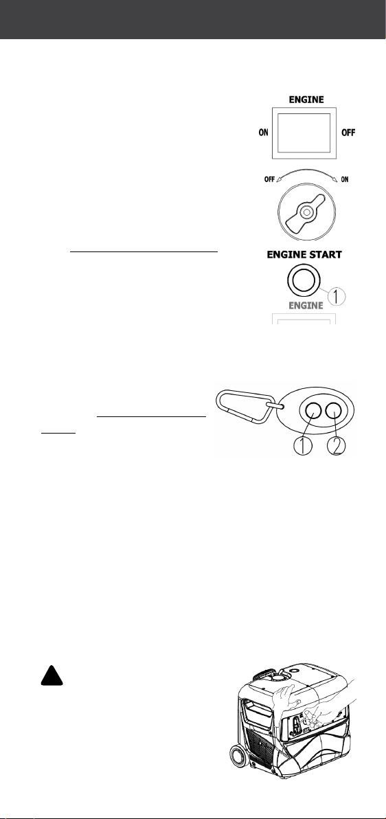
ENGINE SWITCH
OFF: Ignion circuit o; generator stops.
ON: Ignion circuit on; generator OK to
STA RT.
ENGINE START BUTTON
When FUEL SWITCH and the ENGINE
SWITCH are both in the ON posion,
press the ENGINE START buon
① Press buon (green) - The
generator will automacally start (aer a few seconds).
REMOTE CONTROL
When the FUEL SWITCH and ENGINE SWITCH are both
in the ON posion, press START ① on the remote
control and the generator will automacally start (aer
a few seconds). Press STOP ② on the remote control to
shutdown.
① START
② STOP
!NOTE: The remote start distance may be shorter due
to obstacles or baery power reducon. It is suggested to
not exceed 20 metres.
ECO SWITCH
ON: When the ECO SWITCH is ON the
generator runs at idle speed with no load.
When a load is connected, it runs at various
RPMs as per the load, which reduces fuel
consumpon and lowers the noise level.
OFF: The generator will run at its full rated RPM. This
suits equipment that require a high inial output or for
equipment that require high connuous output.
!NOTE: The ECO SWITCH must be set to OFF for
equipment that require a high starng current. E.g.
Compressor submersible pump.

This generator is ed
with two IP23 rated
230V outlets with
weather covers.
LED INDICATORS
① OUTPUT INDICATOR (GREEN)
When the generator is started. The
OUTPUT INDICATOR will turn ON
connuously to show that there is
an output of power.
② OVERLOAD ALARM and RESET BUTTON (RED)
When the total power of connected electrical devices
detected is too close to the rated power, the OVERLOAD
ALARM indicator will turn ON and blink.
When the total power of connected electrical devices
detected overloads the generator, the OVERLOAD
ALARM indicator will turn ON connuously. The
electrical breaker will acvate to stop the power
generaon in order to protect the generator and
connected electric devices. The OUTPUT INDICATOR will
turn OFF, and the OVERLOAD ALARM indicator will stay
ON. The generator will connue to run.
When the generator stops output
due to an overload, disconnect all
electric devices and reduce the
total power of connected electric
devices to a range in the limit of
the generators rated power. Press
the RESET BUTTON and the generator will reset the
power output.

!NOTE: The generator will automacally reset
the power output when the generator is stopped and
restarted. The overload indicator may icker for a
number of seconds inially. When using electric devices
that require a high starng current, such as compressor
or submersible pump. It is not a fault.
③ LOW OIL ALARM (YELLOW)
When oil level falls below the lower limit, the LOW
OIL ALARM indicator will turn on and the engine will
automacally shutdown. Unless you rell the oil the
engine will not restart.
!NOTE: If generator will not start, please turn the
FUEL SWITCH to the ON posion, and then pull the
recoil starter. If the LOW OIL ALARM light ickers for a
few seconds, it means that the oil is insucient. Refer to
page 30 to add/change the oil.
This generator is equipped with a digital display that
provides a connuously updated status of informaon for
the following;
• (V) Voltage output for the generator
• (Hz) Hertz output for the generator
• (Hr) The total run me since the rst start (in hours)
!
The digital display will illuminate when the engine is
turned on. Within a few seconds of illuminaon, the
display will begin to show new data, and at that point
the generator is ready to supply power. The display will
show each reading for a few seconds and repeat the cycle
connuously while running.
Voltage
-V
-Hz
-HR
Hertz
-V
-Hz
-HR
-V
-Hz
-HR

!
FUEL
Remove the fuel tank cap. Add fuel up to the lower red
mark of fuel lter, and then replace the fuel tank cap unl
you hear a clicking sound (Which means the fuel tank cap
is fully ghtened).
Unleaded petrol: #92 or above
Fuel tank capacity: 7.0L
① Red mark in fuel lter
② Fuel level
!
!
!
!
!
!

ENGINE OIL
For new unit or changing oil, place the generator
horizontally, remove the maintenance cover (See page 30),
take out oil plug and ll with 600ml of recommended oil
unl the oil reaches the lower level.
When relling, the oil level should be at the same
level of oil port lower level. Assemble the oil plug and
maintenance cover in reverse procedures (See page 27 for
cover removal).
① Oil port lower level.
② Oil port
③ Oil plug
!
!
RECOMMENDED ENGINE OIL
A: SAE15W-40
B: SAE10W-30
C: SAE5W-30
ENGINE OIL CAPACITY
600ml
!

The ground terminal on this generator is connected to
NON-current carrying parts of the generator frame and to
each AC outlet.
Before aaching a ground (earth)
lead, consult with a qualied
electrician on the intended use of this
generator.
① Ground (earth) terminal
The generator uses a mul-funcon power pack as its
baery for starng the generator.
This power pack also features mulple charging points.
Including; two USB outlets, one MICRO USB outlet and a
DC 12V outlet for charging a range of equipment such as
mobile phones, laptops, etc. There is also a torch, a jump
starter for emergency starng of a car, and a seatbelt
cuer.
!
Ensure the mul-funcon power pack is connected before
starng the generator. To access, remove the power pack
cover and connect the two cables. See below.
① Two screws ④ Connecng cable
② Baery cover ⑤ Charging cable
③ Mul-funcon power pack (baery)

OPERATION INSTRUCTIONS
!
!
!
!
!
•
•
•
STARTING THE GENERATOR
The generator has three types of starng, including
ELECTRIC START, REMOTE START and
RECOIL START.
ELECTRIC START
1. Turn the ENGINE SWITCH to ON.
2. Turn the FUEL SWITCH to ON.
3. Turn ECO SWITCH to OFF.
4. Press the ENGINE START buon
(green) to start the generator (once
only. Do not hold buon down.
REMOTE START
1. Turn the ENGINE SWITCH to ON.
2. Turn the FUEL SWITCH to ON.
3. Turn ECO SWITCH to OFF.
4. Press START (once only) on the remote control and
the generator will start
automacally (aer a few
seconds). Do not hold buon
down.
① START
② STOP
RECOIL START
1. Turn the ENGINE SWITCH to ON.
2. Turn the FUEL SWITCH to ON.
3. Turn ECO SWITCH to OFF.
4. Pull slowly on the recoil start handle unl engine
compression has reached maximum resistance. Carefully
allow the recoil start handle to fully retract. Then pull
smoothly and swily to START.
!
Table of contents
Other Cromtech Portable Generator manuals


Popular Portable Generator manuals by other brands

Baumer
Baumer HUBNER TDPZ 0,2 Series Installation and operating instructions

Mase
Mase VS 10.5 Use, maintenance and installation manual

Woodward
Woodward EGCP-1 Operation and Users Manual

Ingersoll-Rand
Ingersoll-Rand G 220 Users guide and maintenance manual

Smarter tools
Smarter tools GP-3750 owner's manual

BERGER
BERGER Powerstation BPS600 user manual


