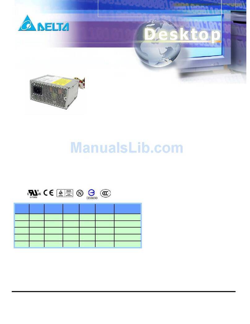
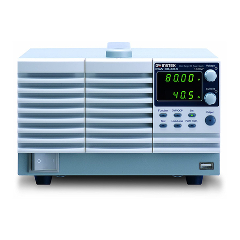
Crouzet IPS12 Assembly instructions

INSTALLATION SHEET
Industrial Power Supply
IPS12 & IPS24
IPS12 IPS24
AC to DC
AC to DC
CROUZET RANGE OF DIN RAIL INDUSTRIAL POWER SUPPLIES, from 60 to 480 W at 12 & 24 Vc. With its narrow width (from 43 to 60 mm max), they are designed
for a wide range of industrial applications. Characterised by their wide voltage input ranges (90 to 264 Va), they allow the supply of single-phase mains electric power to
DC power lines. With a high efficiency of up to 87 % @230 V, these new power supplies will fully satisfy the need of 12 & 24 Vcapplications.
Please refer to the data sheet available on www.crouzet.com
Industrial Power Supply
•Industrial 12 VcPower Supplies range
from 60 to 216 W
•High Efficiency, up to 87% @ 230 Va
•DIN Rail Mount
•UL & CE Certifications
Industrial Power Supply
•Industrial 24 VcPower Supplies range
from 60 to 480 W
•High Efficiency, up to 87% @ 230 Va
•DIN Rail Mount
•UL & CE Certifications
Ref.: 70105301_EN
For more information please go to www.crouzet.com
PART NUMBER NOMENCLATURE
IPS12 89 452 061
89 452 061
89 452 061
IPS 60
W: 60
W: 96
W: 216
IPS12
Series
Series
Output
Power
Part Number
IPS24 89 452 062
89 452 122
89 452 242
89 452 242
IPS 60
W: 60
W: 120
W: 240
W: 480
IPS24
Series
Series
Output
Power
Part Number
POWER SUPPLY REMOVAL FROM DIN RAIL
Switch main power off and disconnect your system from the supply network.
Move the removal hole on the rear down edge downwards by rotating screw driver.
Gently lift lower front edge of the unit (tipping) and remove it.
MOUNTING INSTRUCTIONS
MOUNTING ON DIN RAIL DISMOUNTING
2
3
1
DIN rail connected to
protection wire (ground).
Refer to the derating curve. Do not exceed the load deratings. Keep ventilation
holes clear, leave enough space for cooling.
Please contact your local sales for particular application related to surrounding
space.
1. Unit slightly rearwards, fit the unit over top hat rail.
2. Slide it downward until it hits the stop.
3. Press against the bottom front side for locking.
Shake the unit slightly to check the locking action.
WARNING: Make sure input and output wire disconnected when mount
power supply onto rail.
!
DERATING CURVES
Output Power (%)
Ambient Temperature (°C)
12 Vc& 24 Vc
60 W - 96 W - 120 W - 240 W - 216 W - 480 W
-25
0
40
20
60
80
100
-10 10 30 50 70
°C
WARNINGPROTECTIONS
Input Fuse
Output
Over Load
Output
Short Circuit
Output
Over Voltage
Over
temperature
2A (60W), 3.15A (96W/120W), 4A (216W/240W), 8A (480W)
- 250 VaInternal
≥110% (60W/96W/120W), 110➝140% (216W/240W/480W)
of rated output current
Protection type: Hiccup mode ; recovers automatically after fault
condition is removed
Hiccup mode when output is shorted ; Recovers automatically
after condition is removed
IPS12:17Vc± 1Vc(60W/96W), 16Vc± 0.5Vc(216W),
IPS24: 31.5Vc± 1Vc(60W/120W),
31.5Vc± 0.5Vc(240W/480W)
Protection type: Latched ; Input apower has to be recycled to
recover the power supply
(60W/96W/120W/480W) Power supply shuts down when the
tempertarure of PCB below main transformer reaches typically
120°C ; Turns on only after the temperature falls below 90°C
typically an apower is recycled there after.
(216W/240W) Power supply shuts down when the tempertarure of
PCB below PFC main transformer reaches typically 120°C ;
Recovers automatically when temperature falls to typically 90°C.

INSTALLATION SHEET
Industrial Power Supply
IPS12 & IPS24
Ref.: 70105301_EN
For more information please go to www.crouzet.com
INSTALLING / STORAGE ENVIRONMENT
1. Store the product with ambient temperature -40 to + 85 °C, and relative humidity
5 to 95 % (No Dewdrop).
2. Avoid operating the unit in over current, short circuit conditions or outside the
specified input voltage range as damage may occur.
3. Confirm connections to input/output terminals are correct as indicated in the
instruction manual.
4. Use the product where the relative humidity is 5 to 95 % (No Dewdrop).
5. Avoid places where the product is subjected to direct sun light.
6. Avoid places where the product is subjected to penetration of liquid, foreign
substance or corrosive gas.
7. A device such as a contact breaker may be a vibration source. Set the Power
Supply as far as possible from possible sources of shock or vibration.
8. If the Power Supply is used in an area with excessive electronic noise, be sure to
separate the Power Supply as far as possible from the noise sources.
9. Don’t use the product in the environment with strong electromagnetic field,
corrosive gas and conductive substance.
SAFETY INSTRUCTIONS
• This manual is meant for personnel involved in wiring installation operation &
routine maintenance of the equipment.
• Disconnect power supply of your system before starting any installation
operation or wiring.
• Improper installation operation or wiring may impair safety & failure of the unit
or electrical shock or damage.
• Connect the ground completely. A protective earthing terminal stipulated in
safety standards is used. Electric shock or malfunction may occur if ground is
not connected property.
CERTIFICATIONS
CE Marking, when applied to a product covered by this handbook indicates
compliance with :
• Restriction Of the use of certain Hazardous Substances Directive 2011/65/EU
(RoHS)
• LVD Directive 2014/35/EU
• EMC Directive 2014/30/EU
• UL-508 approved • UKCA
WIRING DIAGRAM
IPS12 - 60 W- 96 W - 216 W IPS24 - 60 W- 120 W - 240 W - 480 W
100 - 240 VAC
12 VDC / 5 A
+
-
DC OK
V. ADJ
28
IPS12-60W
LN
DC OK
V. ADJ
12 14
POWER
SUPPLY
60W
IPS24-480W
100 - 240 VAC
12 VDC / 8 A
+
-
-
+
DC OK
V. ADJ
28
IPS12-120W
LN
DC OK
V. ADJ
12 14
POWER
SUPPLY
96W
12 VDC / 18 A
+
-
+
-
DC ON
DC OK
V. ADJ
12 14
POWER
SUPPLY
216W
100 - 240 VAC
IPS12-240W
LN
100 - 240 VAC
24 VDC / 2.5 A
+
-
DC OK
V. ADJ
28
IPS24-60W
LN
DC OK
V. ADJ
24 28
POWER
SUPPLY
60W
100 - 240 VAC
24 VDC / 5 A
+
-
-
+
IPS24-120W
LN
DC OK
V. ADJ
24 28
POWER
SUPPLY
120W
IPS24-240W
Output terminal
Output terminal
Green LED lights when Output Voltage on
AC Input terminal Live line (fuse in line)
AC Input terminal Neutral line
Output voltage adjust trimmer.
The output voltage rises when a trimmer is turned clockwise.
PE (Protective Earth ) Input
+
-
DC OK
L
N
V. ADJ
WIRING INSTRUCTIONS
1. To prevent risk of electric shock, power supply equipment must be
kept OFF while wiring.
2. Terminals and electrically charged parts must not be touched when the
power is ON.
3. Wiring shall be done strictly according to terminal layout provided in the
operating manual.
WARNINGWARNING
BEFORE USING THE POWER SUPPLY UNIT
Pay attention to all warnings and cautions before using the unit. Incorrect usage
could lead to an electrical shock, damage to the unit or a fire hazard.
• Do not modify, disassemble the power supply.
• Read instruction manual before connecting to mains.
• Do not use the power supply without proper grounding (Protective Earth).
• Minor electric shock, fire or product failure may occasionally occur. do not
allow any pieces of metal or conductors or any clippings or cuttings resulting
from installation work to enter the product.
• Electric shock hazardous on the connector section.
• WEEE symbol for electrical and electronic equipment waste management.
WARNING
HAZARD OF ELECTRIC SHOCK, EXPLOSION OR ARC FLASH
!
WARNING
TERMINAL CONNECTING METHOD
• Pay attention to the input wiring. If it is connected to wrong terminal, the power
supply will be damaged.
• Input must be off when making connections.
• The output load line and input line shall be separated and twisted to improve
noise sensitivity.
• When connecting or removing input and output wire, do not apply stress to
PCB.
+
-
L
N
LOAD
a

FICHE D’INSTALLATION
Alimentations industrielles
IPS12 et IPS24
IPS12 IPS24
AC en DC
AC to DC
LA GAMME CROUZET D'ALIMENTATIONS INDUSTRIELLES SUR RAIL DIN de 60 à 480 W à 12 et 24 VDC. Avec sa largeur étroite (de 43 à 60 mm maxi), elles sont conçues
pour un vaste éventail d'applications industrielles. Caractérisées par leurs larges plages de tensions d'entrées (90 à 264 VAC), elles permettent l'alimentation de lignes
électriques principales monophasées et lignes électriques DC. Avec un haut rendement allant jusqu'à 87 % à 230 V, ces nouvelles alimentations répondront avec succès
au besoin des applications de 12 et 24 VDC.
Veuillez vous reporter à la fiche technique disponible sur www.crouzet.fr
Alimentation industrielle
•La gamme d'alimentations industrielles de
12 VDC s'étend de 60 à 216 W
•Haut rendement, jusqu'à 87 % à 230 VAC
•Fixation sur rail DIN
•Certifications UL et CE
Alimentation industrielle
•La gamme d'alimentations industrielles de
24 VDC s'étend de 60 à 480 W
•Haut rendement, jusqu'à 87 % à 230 VAC
•Fixation sur rail DIN
•Certifications UL et CE
Réf. : 70105301_FR
Pour en savoir plus, nous vous invitons à visiter le site www.crouzet.fr
RÉFÉRENCE NOMENCLATURE
IPS12 89 452 061
89 452 061
89 452 061
IPS 60
W: 60
W: 96
W: 216
Série
IPS12
Série
Puissance
de sortie
Référence
IPS24 89 452 062
89 452 122
89 452 242
89 452 242
IPS 60
W: 60
W: 120
W: 240
W: 480
Série
IPS24
Série
Puissance
de sortie
Référence
DÉPOSE D'UNE ALIMENTATION D'UN RAIL DIN
Couper l'alimentation principale puis débrancher votre système du réseau électrique.
Déplacer le trou de dépose situé sur le bord arrière inférieur vers le bas à l'aide d'un
tournevis.
Lever légèrement le bord avant inférieur de l'unité (en l'inclinant) et le déposer.
CONSIGNES DE FIXATION
FIXATION SUR RAIL DIN DÉMONTAGE
2
3
1
Rail DIN connecté à un fil de
protection (masse).
Se référer à la courbe de réduction de charge. Ne pas dépasser les réductions de
charge. Conserver les orifices de ventilation dégagés, laisser un espace suffisant
pour le refroidissement.
Veuillez contacter votre représentant commercial local pour les applications
particulières en termes d'espace aux alentours.
1. Unité légèrement vers l'arrière, monter l'unité par-dessus le rail symétrique
supérieur.
2. La faire coulisser vers le bas jusqu'à ce qu'elle touche la butée.
3. Exercer une pression contre la face avant inférieure pour assurer le
verrouillage.
Secouer légèrement l'unité pour vérifier l'action de verrouillage.
ATTENTION : S'assurer que le fil d'entrée et le fil de sortie sont
déconnectés lors de la fixation de l'alimentation sur rail.
!
COURBES DE RÉDUCTION DE CHARGE
Puissance de sortie (%)
Température ambiante (°C)
12 VDC et 24 VDC
60 W - 96 W - 120 W - 240 W - 216 W - 480 W
-25
0
40
20
60
80
100
-10 10 30 50 70
°C
WARNINGPROTECTIONS
Fusible
d'entrée
Sortie
Surcharge
Sortie
Court-circuit
Sortie
Surtension
Température
excessive
2 A (60 W), 3,15 A (96 W/120 W), 4 A (216 W/240 W), 8 A (480 W)
- 250 VAC interne
≥110 % (60 W/96 W/120 W), 110 ¬140 % (216 W/240 W/480 W)
de courant de sortie nominal
Type de protection : Mode hiccup ; restauration automatique après
la suppression de la condition d'anomalie
Mode hiccup en cas de sortie court-circuitée ; restauration
automatique après la suppression de la condition
IPS12:17 VDC ± 1 VDC (60 W/96 W),
16 VDC ± 0,5 VDC (216 W),
IPS24: 31,5 VDC ± 1 VDC (60 W/120 W),
31,5 VDC ± 0,5 VDC (240 W/480 W)
Type de protection : Verrouillée ; entrée de puissance devant être
réactivée pour restaurer l’alimentation
(60 W/96 W/120 W/480 W) L’alimentation s’arrête lorsque la
température du PCB sous le transformateur principal atteint
120 °C ; l’alimentation ne se met sous tension qu'une fois que la
température retombe en dessous de 90 °C et que l'alimentation
est réactivée.
(216 W/240 W) L’alimentation s’arrête lorsque la température du
PCB sous le transformateur principal PFC atteint 120 °C ;
l’alimentation se rétablit automatiquement lorsque la température
retombe à 90 °C.

FICHE D’INSTALLATION
Alimentations industrielles
IPS12 et IPS24
Réf. : 70105301_FR
Pour en savoir plus, nous vous invitons à visiter le site www.crouzet.fr
ENVIRONNEMENT D'INSTALLATION/DE STOCKAGE
1. Conservez le produit à une température ambiante -40 à +85 °C et une humidité
relative de 5 à 95 % (sans condensation).
2. Évitez de faire fonctionner l’unité dans des conditions de surintensité, de
court-circuit ou en dehors de la plage de tensions d’entrée spécifiée au risque
de l'endommager.
3. Vérifier que les connexions aux bornes d’entrée/sortie sont correctes comme
indiqué dans le manuel d’instructions.
4. Utilisez le produit avec une humidité relative de 5 à 95 % (Sans condensation).
5. Évitez les endroits où le produit est soumis à la lumière directe du soleil.
6. Évitez les endroits où le produit est soumis à la pénétration de liquide, de corps
étrangers ou de gaz corrosif.
7. Un dispositif tel qu'un rupteur peut être une source de vibrations. Placez
l’alimentation aussi loin que possible des sources potentielles de choc ou de
vibration.
8. Si l'alimentation est utilisée dans une zone où le bruit électronique est excessif,
veillez à installer l'alimentation au plus loin des sources de bruit.
9. N’utilisez pas le produit dans un environnement présentant un important champ
électromagnétique, un gaz corrosif ou une substance conductrice.
CONSIGNES DE SÉCURITÉ
• Ce manuel est destiné au personnel impliqué dans le câblage de l'installation
et la maintenance de routine de l’équipement.
• Débranchez l’alimentation de votre système avant de commencer toute
procédure de pose ou opération de câblage.
• Une procédure de pose incorrecte ou un câblage incorrect peut entraver la
sécurité et endommager l'unité ou provoquer un choc électrique ou des
dommages.
• Connectez complètement la masse. Une borne de mise à la terre de
protection conforme aux normes de sécurité est utilisée. Un choc électrique
ou un dysfonctionnement peut survenir si la terre n’est pas connectée
correctement.
CERTIFICATIONS
Le marquage CE, lorsqu'il est appliqué à un produit couvert par ce manuel, indique
la conformité avec :
• Directive 2011/65/UE relative à la limitation de l’utilisation de certaines
substances dangereuses (RoHS)
• Directive LVD 2014/35/UE
• Directive EMC 2014/30/UE
• Homologuée UL-508 • UKCA
SCHÉMA DE CÂBLAGE
IPS12 - 60 W- 96 W - 216 W IPS24 - 60 W- 120 W - 240 W - 480 W
Borne de sortie
Borne de sortie
La LED verte s’allume lorsque la tension de sortie est activée
Borne d’entrée AC phase (fusible en ligne)
Borne d’entrée AC neutre
Réglage de la tension de sortie trimmer.
La tension de sortie augmente lorsqu'un potentiomètre est tourné
dans le sens des aiguilles d’une montre.
Entrée PE (Terre protectrice)
+
-
DC OK
L
N
V. ADJ
CONSIGNES DE CÂBLAGE
1. Pour éviter tout risque de choc électrique, l’équipement d’alimentation doit
être maintenu HORS TENSION pendant le câblage.
2. Les bornes et les pièces chargées électriquement ne doivent pas être
touchées lorsque l’alimentation est SOUS TENSION.
3. Le câblage doit être effectué strictement conformément à la disposition des
bornes prévue dans le manuel d’utilisation.
WARNINGATTENTION
AVANT D’UTILISER L'UNITÉ D’ALIMENTATION
Faites attention à tous les avertissements et précautions avant d’utiliser l’unité.
Une utilisation incorrecte pourrait entraîner un choc électrique, l'endommagement
de l'unité ou un risque d'incendie.
• Ne pas modifier, démonter l’alimentation.
• Lisez le manuel d’instructions avant de vous connecter au secteur.
• N’utilisez pas l’alimentation électrique sans mise à la terre appropriée (Terre
protectrice).
• Un choc électrique mineur, un incendie ou une défaillance du produit peut le
cas échéant se produire. Empêchez toute introduction dans le produit de
morceaux de métal, de conducteurs, d'attaches ou de résidus de découpe
résultant de travaux d’installation.
• Choc électrique dangereux sur la section connecteur.
• Symbole DEEE pour la gestion des déchets d’équipements électriques et
électroniques.
ATTENTION
RISQUE DE CHOC ÉLECTRIQUE, D'EXPLOSION OU D'ÉCLAIR D'ARC ÉLECTRIQUE
!
WARNING
MÉTHODE DE CONNEXION DES BORNES
• Faites attention au câblage d’entrée. S’il est connecté à une mauvaise borne,
l’alimentation sera endommagée.
• L’entrée doit être désactivée lors de l’établissement de connexions.
• La ligne de charge de sortie et la ligne d’entrée doivent être séparées et
torsadées pour améliorer la sensibilité au bruit.
• Lors de la connexion ou du retrait du fil d’entrée et du fil de sortie,
n’appliquez pas de contrainte sur le PCB.
+
-
L
N
CONTRÔLE DE
a
100 - 240 VAC
12 VDC / 5 A
+
-
DC OK
V. ADJ
28
IPS12-60W
LN
DC OK
V. ADJ
12 14
POWER
SUPPLY
60W
IPS24-480W
100 - 240 VAC
12 VDC / 8 A
+
-
-
+
DC OK
V. ADJ
28
IPS12-120W
LN
DC OK
V. ADJ
12 14
POWER
SUPPLY
96W
12 VDC / 18 A
+
-
+
-
DC ON
DC OK
V. ADJ
12 14
POWER
SUPPLY
216W
100 - 240 VAC
IPS12-240W
LN
100 - 240 VAC
24 VDC / 2.5 A
+
-
DC OK
V. ADJ
28
IPS24-60W
LN
DC OK
V. ADJ
24 28
POWER
SUPPLY
60W
100 - 240 VAC
24 VDC / 5 A
+
-
-
+
IPS24-120W
LN
DC OK
V. ADJ
24 28
POWER
SUPPLY
120W
IPS24-240W

INSTALLATIONSANLEITUNG
Industrielle Netzteile
IPS12 und IPS24
IPS12 IPS24
Wechselstrom
zu Gleichstrom
Wechselstrom
zu Gleichstrom
CROUZETS SERIE VON INDUSTRIELLEN NETZTEILEN FÜR DIN-SCHIENEN – VON 60 BIS 480 W SOWIE MIT 12 und 24 VDC Mit ihrer geringen Breite (von 43 mm bis maximal
60 mm) sind sie für eine Vielzahl von industriellen Anwendungen geeignet. Sie zeichnen sich durch ihre großen Eingangsspannungsbereiche aus (90 bis 264 VAC) und
ermöglichen das Einspeisen von einphasigem Netzstrom in Gleichstromleitungen. Mit einem hohen Wirkungsgrad von bis zu 87 % bei 230 V werden diese neuen
Netzteile den Anforderungen von Anwendungen mit 12 und 24 VDC voll gerecht.
Siehe dazu das Datenblatt auf www.crouzet.de
Industrielles Netzteil
•Industrielle Netzteile mit 12 Vc im Bereich zwischen
60 und 216 W
•Hoher Wirkungsgrad von bis zu 87 % bei 230 VAC
•DIN-Schienenmontage
•Zulassung gemäß UL und CE
Industrielles Netzteil
•Industrielle Netzteile mit 12 VDC im Bereich
zwischen 60 und 480 W
•Hoher Wirkungsgrad von bis zu 87 % bei 230
VAC
•DIN-Schienenmontage
•Zulassung gemäß UL und CE
Ref.: 70105301_DE
Für weitere Informationen, siehe www.crouzet.de
NOMENKLATUR DER TEILENUMMERN
IPS12 89 452 061
89 452 061
89 452 061
IPS 60
W: 60
W: 96
W: 216
Serie
IPS12
Serie Ausgangsleistung
Teilenummer
IPS24 89 452 062
89 452 122
89 452 242
89 452 242
IPS 60
W: 60
W: 120
W: 240
W: 480
Serie
IPS24
Serie Ausgangsleistung
Teilenummer
ENTFERNEN DES NETZTEILS VON DER DIN-SCHIENE
Die Hauptstromversorgung ausschalten und das System vom Versorgungsnetz
abklemmen.
Die Entnahmeöffnung an der Unterkante der Rückseite durch Drehen des
Schraubendrehers nach unten schieben.
Die untere Vorderkante des Geräts vorsichtig anheben (kippen) und das Gerät
entfernen.
MONTAGEANLEITUNG
MONTAGE AUF DIN-SCHIENE DEMONTAGE
2
3
1
DIN-Schiene angeschlossen
an Schutzdraht (Erde)
Siehe die Derating-Kurve. Die Last-Deratings nicht überschreiten. Die
Lüftungsöffnungen freihalten und genügend Raum für die Kühlung vorsehen.
Bitte wenden Sie sich bei spezifischen Anwendungen für den erforderlichen
umgebenden Raum an Ihren Crouzet-Vertrieb.
1. Die Einheit leicht nach hinten neigen und auf die Hutschiene setzen.
2. Bis zum Anschlag nach unten schieben.
3. Zum Verriegeln unten gegen die Vorderseite drücken.
Um die Verriegelung zu überprüfen, das Gerät leicht schütteln.
WARNHINWEIS : Erst das Eingangskabel und das Ausgangskabel
abklemmen, dann das Netzteil auf die Schiene montieren.
!
DERATING-KURVEN
Ausgangsleistung (%)
Umgebungstemperatur (ºC)
12 VDC und 24 VDC
60 W - 96 W - 120 W - 240 W - 216 W - 480 W
-25
0
40
20
60
80
100
-10 10 30 50 70
°C
WARNINGSCHUTZVORRICHTUNGEN
Eingangssi-
cherung
Ausgang
Überlast
Ausgang
Kurzschluss
Ausgang
Überspan-
nung
Übertempera-
tur
2 A (60 W), 3,15 A (96 W / 120 W), 4 A (216 W / 240 W), 8 A (480
W) – 250 Va intern
≥110 % (60 W / 96 W / 120 W), 110 bis ¬140 % (216 W / 240 W /
480 W)
des Nennausgangsstroms
Schutzart: Hiccup-Modus: Automatisches Wiederherstellen nach
Fehlerbehebung
Hiccup-Modus bei kurzgeschlossenem Ausgang. Automatisches
Wiederherstellen nach Fehlerbehebung.
IPS12:17 VDC ± 1 VDC (60 W / 96 W), 16 VDC ± 0,5 VDC (216W)
IPS24: 31,5 VDC ± 1 VDC (60 W / 120 W)
31,5 V ± 0,5 V (240 W / 480 W)
Schutzart: Verriegelungsschaltung: Eingangsstrom muss zum
Wiederherstellen der Stromversorgung erneut geschaltet werden.
(60 W / 96 W / 120 W / 480 W) Die Stromversorgung wird
abgeschaltet, wenn die Temperatur der Leiterplatte unter dem
Haupttransformator in der Regel 120 °C erreicht. Sie wird erst
wieder eingeschaltet, wenn die Temperatur unter 90 ° C fällt. Der
Strom wird danach erneut geschaltet.
216 W / 240 W) Die Stromversorgung wird abgeschaltet, wenn die
Temperatur der Leiterplatte unter dem PFC-Haupttransformator in
der Regel 120 °C erreicht. Sie wird automatisch wieder
eingeschaltet, wenn die Temperatur auf in der Regel 90 °C fällt.

INSTALLATIONSANLEITUNG
Industrielle Netzteile
IPS12 und IPS24
Ref.: 70105301_DE
Für weitere Informationen, siehe www.crouzet.de
UMGEBUNGSBEDINGUNGEN FÜR INSTALLATION / LAGERUNG
1. Das Produkt zwischen -40 und +85 °C Umgebungstemperatur sowie 5 und
95 % relativer Luftfeuchte (tautropfenfrei) lagern.
2. Das Gerät gerät nicht bei Überstrom, Kurzschluss oder außerhalb des
angegebenen Eingangsspannungsbereichs betreiben. Das Gerät könnte dabei
beschädigt werden.
3. Überprüfen, ob die Anschlüsse an den Eingangsklemmen und den
Ausgangsklemmen den Vorgaben der Bedienungsanleitung entsprechen.
4. Das Produkt nur bei einer relativen Luftfeuchtigkeit von 5 bis 95 % (tautropfenfrei)
betreiben.
5. Orte mit direkter Sonnenstrahlung auf das Produkt vermeiden.
6. Orte vermeiden, an denen das Produkt dem Eindringen von Flüssigkeiten,
Fremdstoffen oder korrosiven Gasen ausgesetzt ist.
7. Geräte wie Trennschalter können Vibrationsquellen sein. Das Netzteil so weit wie
möglich von möglichen Stoß- oder Vibrationsquellen entfernt einrichten.
8. Falls das Netzteil in Bereichen mit übermäßigem elektronischem Rauschen
verwendet wird, das Netzteil so weit wie möglich von den Störquellen isolieren.
9. Das Produkt nicht in Umgebungen mit starken elektromagnetischen Feldern,
korrosiven Gasen und leitfähigen Substanzen einsetzen.
SICHERHEITSANWEISUGEN
• Dieses Handbuch richtet sich an Personen, die mit der Verdrahtung, dem Betrieb
und der Routinewartung der Ausrüstung befasst sind.
• Erst die Stromversorgung des Systems abklemmen, dann mit der Installation
oder Verdrahtung beginnen.
• Unsachgemäße Installation oder Verdrahtung kann die Sicherheit des Geräts
beeinträchtigen und Ausfall, Stromschlag oder Beschädigung verursachen.
• Die Erdung vollständig einrichten. Verwendet wird eine von den
Sicherheitsnormen vorgegebene Schutzerdungsklemme. Falls die Erdung
fehlerhaft ausgeführt ist, können Stromschlag und Fehlfunktionen die Folge sein.
ZULASSUNGEN
Die CE-Kennzeichnung eines Produkt in dieses Handbuch bedeutet Konformität mit:
• Richtlinie 2011/65/EU zur Beschränkung der Verwendung bestimmter gefährli-
cher Stoffe (RoHS)
• LVD-Richtlinie 2014/35/EU
• EMC-Richtlinie 2014/30/EU
• Zulassung gemäß UL-508 – UKCA • UKCA
SCHALTPLAN
IPS12 - 60 W- 96 W - 216 W IPS24 - 60 W- 120 W - 240 W - 480 W
Ausgangsklemme
Ausgangsklemme
Grüne LED leuchtet bei eingeschalteter Ausgangsspannung
Wechselstrom-Eingangsklemme des stromführenden Leiters
(Sicherung in Leiter)
Wechselstrom-Eingangsklemme des Neutralleiters
Trimmer für Ausgangsspannung
Um die Ausgangsspannung zu erhöhen, den Trimmer im
Uhrzeigersinn drehen.
PE (Schutzerde) Eingang
+
-
DC OK
L
N
V. ADJ
VERDRAHTUNGSANLEITUNG
1. Um Stromschlagrisiken zu vermeiden, müssen Stromversorgungsgeräte beim
Verdrahten AUSGESCHALTET sein.
2. Bei EINGESCHALTETER Stromversorgung dürfen Klemmen und unter Strom
stehende Teile nicht berührt werden.
3. Die Verdrahtung muss genauestens gemäß dem in der Bedienungsanleitung
aufgeführten Klemmenanschlussplan ausgeführt werden.
WARNINGWARNHINWEIS
VOR EINSATZ DES NETZTEILS
Erst alle Warnhinweise und Vorsichtsmaßnahmen beachten, dann das Gerät
verwenden. Falsche Verwendung kann zu Stromschlag, Beschädigung des
Geräts oder Brandgefahr führen.
• Das Netzteil nicht modifizieren und nicht auseinanderbauen.
• Erst die Bedienungsanleitung durchlesen, dann das Gerät an das Stromnetz
anschließen.
• Das Netzteil nicht ohne vorgabegemäße Erdung (Schutzerde) verwenden.
• Gelegentlich können kleinere Stromschläge, Brände oder Produktversagen
auftreten. Keine bei Installationsarbeiten anfallenden Metallstücke,
Leiterstücke oder Verschnitt in das Produkt gelangen lassen.
• Stromschlagrisiko im Anschlussbereich.
• WEEE-Symbol für die Entsorgung von Elektro- und Elektronikgeräten.
WARNHINWEIS
GEFAHR VON STROMSCHLAG, EXPLOSION ODER LICHTBOGENÜBERSCHLAG
!
WARNING
KLEMMENANSCHLUSSVERFAHREN
•Die Eingangsverdrahtung sorgfältigst durchführen. Falscher Klemme-
nanschluss beschädigt das Netzteil.
•Der Eingang muss beim Erstellen von Verdrahtungen ausgeschaltet sein.
•Um den Schutz vor Störgeräuschen zu verbessern, müssen die
Ausgangslastleitung und die Eingangsleitung getrennt verlegt sowie verdrillt
werden.
•Die Leiterplatte beim Anschließen oder Entfernen von Eingangsdrähten und
Ausgangsdrähten keiner mechanischen Belastung aussetzen.
+
-
L
N
LAST
a
100 - 240 VAC
12 VDC / 5 A
+
-
DC OK
V. ADJ
28
IPS12-60W
LN
DC OK
V. ADJ
12 14
POWER
SUPPLY
60W
IPS24-480W
100 - 240 VAC
12 VDC / 8 A
+
-
-
+
DC OK
V. ADJ
28
IPS12-120W
LN
DC OK
V. ADJ
12 14
POWER
SUPPLY
96W
12 VDC / 18 A
+
-
+
-
DC ON
DC OK
V. ADJ
12 14
POWER
SUPPLY
216W
100 - 240 VAC
IPS12-240W
LN
100 - 240 VAC
24 VDC / 2.5 A
+
-
DC OK
V. ADJ
28
IPS24-60W
LN
DC OK
V. ADJ
24 28
POWER
SUPPLY
60W
100 - 240 VAC
24 VDC / 5 A
+
-
-
+
IPS24-120W
LN
DC OK
V. ADJ
24 28
POWER
SUPPLY
120W
IPS24-240W

HOJA DE INSTALACIÓN
Fuente de alimentación industrial
IPS12 e IPS24
IPS12 IPS24
AC a DC
AC a DC
GAMA CROUZET DE FUENTES DE ALIMENTACIÓN INDUSTRIALES CON RAÍL DIN, de 60 W a 480 W en 12 VDC y 24 VDC. De dimensiones reducidas (de 43 a 60 mm), están
diseñadas para una amplia gama de aplicaciones industriales. Caracterizadas por sus amplios rangos de entrada de tensión (de 90 a 264 VAC), permiten el suministro de
energía eléctrica monofásica a las líneas eléctricas de DC. Con una alta eficiencia de hasta el 87 % a 230 V, estas nuevas fuentes de alimentación satisfarán plenamente
las necesidades de las aplicaciones de 12 y 24 VDC.
Consulte la hoja de datos disponible en www.crouzet.com
Fuente de alimentación industrial
• La gama de fuentes de alimentación
industriales de 12 VDC van de 60 a 216 W
•Alta eficiencia, hasta el 87 % a 230 VAC
•Montaje en raíl DIN
•Certificaciones UL y CE
Fuente de alimentación industrial
•La gama de fuentes de alimentación
industriales de 24 VDC van de 60 a 480 W
•Alta eficiencia, hasta el 87 % a 230 VAC
•Montaje en raíl DIN
•Certificaciones UL y CE
Ref.: 70105301_ES
Para obtener más información, visite la página www.crouzet.com
NOMENCLATURA DE LA REFERENCIA
IPS12 89 452 061
89 452 061
89 452 061
IPS 60
W: 60
W: 96
W: 216
Series
IPS12
Serie
Potencia
de salida
Referencia
IPS24 89 452 062
89 452 122
89 452 242
89 452 242
IPS 60
W: 60
W: 120
W: 240
W: 480
Series
IPS24
Serie
Potencia
de salida
Referencia
EXTRACCIÓN DE LA FUENTE DE ALIMENTACIÓN DEL RAÍL DIN
Corte la alimentación principal y desconecte su sistema de la red de suministro.
Desplace el orificio de extracción situado en el borde inferior trasero hacia abajo
girando el destornillador.
Levante con cuidado el borde frontal inferior de la unidad (inclinándolo) y retírela.
INSTRUCCIONES DE MONTAJE
MONTAJE EN RAÍL DIN DESMONTAJE
2
3
1
Raíl DIN conectado al cable
de protección (masa)
Consulte la curva de reducción. No exceda las reducciones de carga.
Mantenga los orificios de ventilación despejados, deje suficiente espacio para
la refrigeración.
Póngase en contacto con su oficina local de ventas para consultar sobre una
aplicación concreta relacionada con el espacio circundante.
1. Incline la unidad ligeramente hacia atrás y colóquela sobre el raíl de perfil
de sombrero superior.
2. Deslícela hacia abajo hasta que llegue al tope.
3. Presione la parte frontal inferior para bloquearla.
Mueva ligeramente la unidad para comprobar que está bien bloqueada.
ADVERTENCIA: Asegúrese de que los cables de entrada y salida estén
desconectados al montar la fuente de alimentación en el raíl.
!
CURVAS DE REDUCCIÓN TÉRMICA
Potencia de salida (%)
Temperatura ambiente (°C)
12 VDC & 24 VDC
60 W - 96 W - 120 W - 240 W - 216 W - 480 W
-25
0
40
20
60
80
100
-10 10 30 50 70
°C
WARNINGPROTECCIONES
IFusible de
entrada
Salida
Sobrecarga
Salida
Cortocircuito
Salida
Sobretensión
Temperatura
excesiva
2 A (60 W), 3,15 A (96 W/120 W), 4 A (216 W/240 W), 8 A (480 W)
- 250 VAC interno
110 % (60 W/96 W/120 W), 110➝140 % (216 W/240 W/480 W)
de corriente nominal de salida
Tipo de protección: Modo hipo; se recupera automáticamente
después de eliminar el estado de error
Modo hipo cuando la salida ha cortocircuitado; se recupera
automáticamente después de eliminar el estado
IPS12: 17 VDC ± 1 VDC (60 W/96 W),
16 VDC ± 0,5 VDC (216 W),
IPS24: 31,5 VDC ± 1 VDC (60 W/120 W),
31,5 VDC ± 0,5 VDC (240 W/480 W)
Tipo de protección: cerrado; la AC de entrada se tiene que reciclar
para recuperar la fuente de alimentación
(60 W/96 W/120 W/480 W) La fuente de alimentación se apaga
cuando la temperatura de la PCB situada debajo del
transformador principal alcanza los 120 °C; no se enciende hasta
que la temperatura haya caído por debajo de los 90 °C y la AC se
recicla después.
(216 W/240 W) La fuente de alimentación se apaga cuando
la temperatura de la PCB situada debajo del transformador
principal PFC alcanza los 120 ºC; se recupera automáticamente
cuando la temperatura desciende a los 90 ºC.

HOJA DE INSTALACIÓN
Fuente de alimentación industrial
IPS12 e IPS24
Ref.: 70105301_ES
Para obtener más información, visite la página www.crouzet.com
ENTORNO DE INSTALACIÓN / ALMACENAMIENTO
1. Conserve el producto a una temperatura ambiente de -40 a +85 °C y con una
humedad relativa del 5 al 95 % (sin gota de rocío).
2. Evite utilizar la unidad en condiciones de sobretensión, cortocircuito o fuera del rango
de tensión de entrada especificado, ya que la unidad puede sufrir daños.
3. Confirme que las conexiones a los terminales de entrada/salida son correctas, tal
como se indica en el manual de instrucciones.
4. Utilice el producto en lugares en los que la humedad relativa sea de entre el
5 y el 95 % (sin gota de rocío).
5. Evite los lugares donde el producto esté sometido a la luz solar directa.
6. Evite los lugares en los que pueda entrar líquido, sustancias extrañas o gases
corrosivos en el producto.
7. Un dispositivo como un interruptor puede ser una fuente de vibración. Sitúe
la fuente de alimentación lo más lejos posible de posibles fuentes de choque
o vibraciones.
8. Si la fuente de alimentación se utiliza en una zona con ruido electrónico excesivo,
asegúrese de separarla en la medida de lo posible de las fuentes de ruido.
9. No utilice el producto en entornos con campos electromagnéticos fuertes, gases
corrosivos y sustancias conductoras.
INSTRUCCIONES DE SEGURIDAD
• Este manual está destinado al personal implicado en la operación de instalación,
cableado y en el mantenimiento rutinario del equipo.
• Desconecte la fuente de alimentación de su sistema antes de iniciar cualquier
operación de instalación o cableado.
• Una operación de instalación o un cableado mal ejecutados pueden afectar a la
seguridad y provocar fallos en la unidad, un choque eléctrico o daños en el equipo.
• Asegúrese de conectar la toma a tierra. Se utiliza un terminal de puesta a tierra de
protección estipulado en las normas de seguridad. Si la toma a tierra no está
conectada de forma adecuada se puede producir un choque eléctrico o un mal
funcionamiento.
CERTIFICACIONES
El marcado CE, cuando hace referencia a un producto incluido en este manual, indica el
cumplimiento de:
• Directiva 2011/65/UE (RoHS) sobre restricciones a la utilización de determinadas
sustancias peligrosas
• Directiva de baja tensión 2014/35/UE
• Directiva de compatibilidad electromagnética 2014/30/UE
• Homologación UL-508 • UKCA
DIAGRAMA DE CABLEADO
IPS12 - 60 W- 96 W - 216 W IPS24 - 60 W- 120 W - 240 W - 480 W
Terminal de salida
Terminal de salida
Luces LED verdes cuando la tensión de salida enciende
Terminal de entrada AC ‐ Fase (Fusible en línea)
Terminal de entrada AC ‐Neutro
Trimmer de ajuste de tensión de salida.
La tensión de salida aumenta cuando el trimmer se gira en el sentido
de las agujas del reloj.
Entrada PE (puesta a tierra de protección)
+
-
DC OK
L
N
V. ADJ
INSTRUCCIONES DE CABLEADO
1. Para evitar el riesgo de choque eléctrico, mantenga apagada la fuente de limentación
durante el cableado.
2. Los terminales y las piezas bajo tensión no deben tocarse cuando la alimentación
está encendida.
3. El cableado se realizará estrictamente de acuerdo con el diseño del terminal incluido
en el manual de instrucciones.
WARNING
ADVERTENCIA
ANTES DE UTILIZAR LA FUENTE DE ALIMENTACIÓN
Preste atención a todas las advertencias y precauciones antes de usar la unidad. El uso
incorrecto podría provocar un choque eléctrico, daños en la unidad o riesgo de incendio.
• No modifique ni desmonte la fuente de alimentación.
• Lea el manual de instrucciones antes de conectar la unidad a la red eléctrica.
• No utilice la fuente de alimentación sin una conexión a tierra adecuada (puesta a
tierra de protección).
• Ocasionalmente se puede producir un choque eléctrico menor, un incendio o un
fallo del producto. No permita la entrada en la unidad de ninguna pieza de metal,
conductor o cualquier esquirla o recorte resultante de los trabajos de instalación.
• Choque eléctrico peligroso en la sección del conector.
• Símbolo RAEE para la gestión de residuos de aparatos eléctricos y electrónicos.
ADVERTENCIA
PELIGRO DE CHOQUE ELÉCTRICO, EXPLOSIÓN O ARCO ELÉCTRICO
!
WARNING
MÉTODO DE CONEXIÓN DEL TERMINAL
• Preste atención al cableado de entrada. Si está conectado al terminal incorrecto,
la fuente de alimentación sufrirá daños.
• La entrada debe estar desconectada a la hora de realizar conexiones.
• La línea de carga de salida y la línea de entrada se deben separar y trenzar
para mejorar la sensibilidad al ruido.
• Al conectar o extraer los cables de entrada y salida, no conecte la tensión
en la PCB.
+
-
L
N
CARGA
a
100 - 240 VAC
12 VDC / 5 A
+
-
DC OK
V. ADJ
28
IPS12-60W
LN
DC OK
V. ADJ
12 14
POWER
SUPPLY
60W
IPS24-480W
100 - 240 VAC
12 VDC / 8 A
+
-
-
+
DC OK
V. ADJ
28
IPS12-120W
LN
DC OK
V. ADJ
12 14
POWER
SUPPLY
96W
12 VDC / 18 A
+
-
+
-
DC ON
DC OK
V. ADJ
12 14
POWER
SUPPLY
216W
100 - 240 VAC
IPS12-240W
LN
100 - 240 VAC
24 VDC / 2.5 A
+
-
DC OK
V. ADJ
28
IPS24-60W
LN
DC OK
V. ADJ
24 28
POWER
SUPPLY
60W
100 - 240 VAC
24 VDC / 5 A
+
-
-
+
IPS24-120W
LN
DC OK
V. ADJ
24 28
POWER
SUPPLY
120W
IPS24-240W

FOGLIO DI INSTALLAZIONE
Alimentatore industriale
IPS12 e IPS24
IPS12 IPS24
Da CA a CC
CA to CC
GAMMA CROUZET DI ALIMENTATORI INDUSTRIALI SU GUIDA DIN, da 60 a 480 W a 12 e 24 VDC. Con una larghezza ridotta (da 43 a 60 mm max), sono progettati per una
vasta gamma di applicazioni industriali. Caratterizzati da un ampio intervallo di tensioni d'ingresso (da 90 a 264 VCA), consentono la fornitura di alimentazione elettrica di
rete monofase a linee di alimentazione CC (DC).Con un alto rendimento fino all'87% a 230 V, questi nuovi alimentatori soddisfano pienamente le esigenze delle
applicazioni da 12 e 24 VCC.
Consultare la scheda tecnica disponibile su www.crouzet.com
Alimentatore industriale
•Gli alimentatori industriali da 12 VCC vanno
da 60 a 216 W
•Alto rendimento, fino all'87% a 230 VCA
•Montaggio su guida DIN
•Omologazioni UL e CE
Alimentatore industriale
•Gli alimentatori industriali da 24 VCC vanno
da 60 a 480 W
•Alto rendimento, fino all'87% a 230 VCA
•Montaggio su guida DIN
•Omologazioni UL e CE
Ref.: 70105301_IT
Per ulteriori informazioni consultare il sito www.crouzet.com
NOMENCLATURA CODICE PRODOTTO
IPS12 89 452 061
89 452 061
89 452 061
IPS 60
W: 60
W: 96
W: 216
Serie
IPS12
Serie
Potenza
utile
Codice prodotto
IPS24 89 452 062
89 452 122
89 452 242
89 452 242
IPS 60
W: 60
W: 120
W: 240
W: 480
Serie
IPS12
Serie
Potenza
utile
Codice prodotto
RIMOZIONE DELL'ALIMENTATORE DALLA GUIDA DIN
Spegnere l'interruttore principale e scollegare il sistema dalla rete di alimentazione.
Spostare il foro di rimozione sul bordo inferiore posteriore verso il basso
ruotando il cacciavite.
Sollevare delicatamente il bordo anteriore inferiore dell'unità (ribaltamento)
e rimuoverlo.
ISTRUZIONI DI MONTAGGIO
MONTAGGIO SU GUIDA DIN RIMOZIONE
2
3
1
Guida DIN collegata al cavo
di protezione (terra)
Fare riferimento alla "curva di declassamento" (derating curve). Non superare i valori
di declassamento di carico. Mantenere liberi i fori di ventilazione, lasciare
abbastanza spazio per il raffreddamento.
Si prega di contattarci per applicazioni particolari relative allo spazio circostante.
1. Inclinare l'unità leggermente all'indietro, montare l'unita sulla guida DIN.
2. Fare scorrere verso il basso finché non scatta in posizione.
3. Premere contro il lato anteriore inferiore per bloccare.
Scuotere leggermente l'unità per verificare che sia fissata correttamente.
ATTENZIONE: Assicurarsi che il cavo di ingresso e di uscita siano scollegati
quando si monta l'alimentatore sulla guida.
!
CURVE DI DECLASSAMENTO
Potenza utile (%)
Temperatura ambiente (°C)
12 VCC e 24 VCC
60 W - 96 W - 120 W - 240 W - 216 W - 480 W
-25
0
40
20
60
80
100
-10 10 30 50 70
°C
WARNINGPROTEZIONI
Fusibile di
ingresso
Uscita
Sovraccarico
Uscita
Corto circuito
Uscita
Sovratensione
Sovratempera-
tura
2A (60W), 3,15A (96W/120W), 4A (216W/240W), 8A (480W) -
250 VCA interni
≥110% (60W/96W/120W), 110➝140% (216W/240W/480W)
della corrente nominale di uscita
Tipo di protezione: Modalità a singhiozzo (hiccup); ritorno
automatico al funzionamento normale dopo la cessazione della
causa
Modalità a singhiozzo (hiccup) in presenza di un cortocircuito sul
lato uscita; ritorno automatico al funzionamento normale dopo la
cessazione della causa
IPS12:17Vc ± 1Vc (60W/96W), 16Vc ± 0,5Vc (216W),
IPS24: 31,5Vc ± 1Vc (60W/120W),
31,5 V c ± 0,5 V c (240 W/480 W)
Tipo di protezione: Blocco; L'alimentazione in ingresso deve
essere rigenerata (riconnessa) per ripristinare l'alimentazione
(60W/96W/120W/480W) L'alimentatore di solito si spegne quando
la temperatura del circuito stampato collegato al trasformatore di
alimentazione raggiunge i 120°C; si riaccende solo quando la
temperatura scende di nuovo sotto i 90°C, dopodichè in genere
viene ripristinata l' alimentazione in ingresso.
(216W/240W) L'alimentatore di solito si spegne quando la
temperatura del circuito stampato collegato al trasformatore di
alimentazione PFC raggiunge i 120°C; si ripristina automatica-
mente quando la temperatura scende di nuovo a 90°C.

FOGLIO DI INSTALLAZIONE
Alimentatore industriale
IPS12 e IPS24
Ref.: 70105301_IT
Per ulteriori informazioni consultare il sito www.crouzet.com
CONDIZIONI DI INSTALLAZIONE / CONSERVAZIONE
1. Conservare il prodotto a temperatura ambiente da -40 a + 85 °C e con
un'umidità relativa tra il 5 e il 95 % (senza condensa).
2. Evitare di utilizzare l'unità in condizioni di sovracorrente, cortocircuito o al di fuori
dell'intervallo di tensione di ingresso specificato per prevenire possibili danni.
3. Verificare che i collegamenti ai terminali di ingresso/uscita siano corretti, come
indicato nel manuale di istruzioni.
4. Utilizzare il prodotto se l'umidità relativa è compresa tra il 5 e il 95 % (senza
condensa).
5. Evitare l'esposizione diretta alla luce solare.
6. Evitare il contatto con liquidi, sostanze estranee o gas corrosivi.
7. Un dispositivo come un ruttore può essere una fonte di vibrazioni. Collocare
l'alimentatore il più lontano possibile da possibili fonti di urti o vibrazioni.
8. Se l'alimentatore viene utilizzato in un'area con un rumore elettronico estremo,
assicurarsi di isolare l'alimentatore, tenendolo il più lontano possibile dalle fonti di
disturbo.
9. Non utilizzare il prodotto in presenza di forti campi elettromagnetici, gas corrosivi
e sostanze conduttive..
ISTRUZIONI DI SICUREZZA
• Questo manuale è destinato al personale coinvolto nelle operazioni di collega-
mento e responsabile della manutenzione ordinaria delle apparecchiature.
• Scollegare l'alimentazione del sistema prima di iniziare qualsiasi operazione di
installazione o collegamento.
• Un'installazione o un collegamento mal eseguiti possono compromettere la
sicurezza e provocare guasti dell'unità, scosse elettriche o danneggiamenti.
• Mettere a terra tutto l'impianto. Viene utilizzato un terminale di messa a terra
di protezione in conformità agli standard di sicurezza. In caso di errato
collegamento della messa a terra esiste il rischio di scariche elettriche o
malfunzionamenti.
CERTIFICAZIONI
Il marchio CE, se applicato a un prodotto contemplato dal presente manuale, indica
la conformità a:
• Direttiva 2011/65/UE (RoHS) per la limitazione dell'uso di determinate sostanze
pericolose
• Direttiva LVD 2014/35/UE
• Direttiva EMC 2014/30/UE
• Omologazione UL-508 • UKCA
SCHEMA DI COLLEGAMENTO
IPS12 - 60 W- 96 W - 216 W IPS24 - 60 W- 120 W - 240 W - 480 W
Terminale di uscita
Terminale di uscita
Il LED verde si accende quando la tensione di uscita è attiva
Terminale di ingresso linea CA in tensione (fusibile in linea)
Terminale di ingresso linea CA neutro
Regolatore di tensione di uscita.
La tensione di uscita aumenta quando il regolatore viene ruotato
in senso orario.
Ingresso PE (Protective Earth - Messa a terra di protezione)
+
-
DC OK
L
N
V. ADJ
ISTRUZIONI PER IL CABLAGGIO
1. Per prevenire il rischio di scosse elettriche, le apparecchiature di alimentazione
devono essere mantenute spente durante il collegamento.
2. I terminali e le parti sotto tensione non devono essere toccati quando
l'alimentazione è accesa.
3. Il collegamento deve essere effettuato rigorosamente secondo lo schema dei
terminali fornito nel manuale operativo.
WARNINGATTENZIONE
PRIMA DI UTILIZZARE L'ALIMENTATORE
Prestare attenzione a tutte le avvertenze e le precauzioni da adottare prima di
utilizzare l'unità. Un uso scorretto potrebbe causare una scossa elettrica,
provocare danni all'unità o un incendio.
• Non modificare, smontare l'alimentatore.
• Leggere il manuale di istruzioni prima di collegarsi alla rete elettrica.
• Non utilizzare l'alimentatore senza un'adeguata messa a terra (messa a terra
di protezione).
• Possono occasionalmente verificarsi lievi scosse elettriche o guasti del
prodotto. Non permettere che pezzi di metallo o cavi, ritagli o residui derivanti
da lavori di installazione finiscano all'interno del prodotto.
• Pericolo di scossa elettrica nella sezione del connettore.
• Simbolo RAEE per la gestione dei rifiuti di apparecchiature elettriche ed
elettroniche.
ATTENZIONE
PERICOLO DI SCOSSA ELETTRICA, ESPLOSIONE O ARCO ELETTRICO
!
WARNING
METODO DI COLLEGAMENTO DEI TERMINALI
• Prestare attenzione al collegamento di ingresso. Se il cablaggio viene collega-
to a un terminale sbagliato può provocare danni all'alimentatore.
• La corrente deve essere staccata quando si effettuano dei collegamenti.
• La linea di carico in uscita e la linea di ingresso devono essere separate e
attorcigliate per migliorare la sensibilità alle interferenze.
• Quando si collega o si rimuove il cavo di ingresso e di uscita, fare attenzione
a non applicare pressione al circuito stampato.
+
-
L
N
CARICO
a
100 - 240 VAC
12 VDC / 5 A
+
-
DC OK
V. ADJ
28
IPS12-60W
LN
DC OK
V. ADJ
12 14
POWER
SUPPLY
60W
IPS24-480W
100 - 240 VAC
12 VDC / 8 A
+
-
-
+
DC OK
V. ADJ
28
IPS12-120W
LN
DC OK
V. ADJ
12 14
POWER
SUPPLY
96W
12 VDC / 18 A
+
-
+
-
DC ON
DC OK
V. ADJ
12 14
POWER
SUPPLY
216W
100 - 240 VAC
IPS12-240W
LN
100 - 240 VAC
24 VDC / 2.5 A
+
-
DC OK
V. ADJ
28
IPS24-60W
LN
DC OK
V. ADJ
24 28
POWER
SUPPLY
60W
100 - 240 VAC
24 VDC / 5 A
+
-
-
+
IPS24-120W
LN
DC OK
V. ADJ
24 28
POWER
SUPPLY
120W
IPS24-240W
This manual suits for next models
1
Table of contents
Languages:
