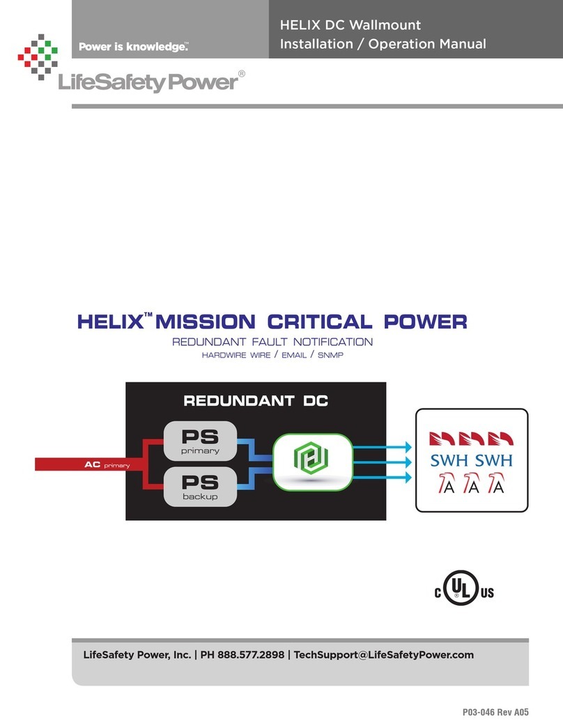
RH Series Rackmount Helix Installation Manual
iv 1
Installation and Operation
Introduction
DC Product Power Outputs Description
RH75 Series 75W 2 Single Voltage 6A @ 12VDC or 3A @ 24VDC / dual output
RH150 Series 150W 2 Single Voltage 12A @ 12VDC or 6A @ 24VDC / dual output
RH250 Series 250W 2 Single Voltage 20A @ 12VDC or 10A @ 24VDC / dual output
Remote monitoring
RH75-XN 75W 8, 16 Single Voltage / Network 6A @ 12VDC or 3A @ 24VDC / multiple outputs / network
RH150-XN 150W 8, 16 Single Voltage / Network 12A @ 12VDC or 6A @ 24VDC / multiple outputs / network
RH250-XN 250W 8, 16 Single Voltage / Network 20A @ 12VDC or 10A @ 24VDC / multiple outputs / network
The LifeSafety Power Helix RH rackmount power supplies are
a redundant power source for use in the Access Control indus-
try. Two identical FPO power supplies are combined in a single
enclosure with the Helix module to provide a single output
voltage. In the event of a failure of the main power source, the
Helix module will automatically switch the output to the back-
up FPO power supply. Designed to fit neatly into standard 19"
equipment racks, the streamlined cabinetry and exceptional
features combine to significantly reduce installation and ser-
vice costs. Features include removable terminal strips for field
wiring, input and output surge suppression, automotive blade
fuses for improved reliability, a front removable chassis face
plate for serviceability and is enclosed in a 16 gauge steel 2U
rack mount chassis.
The Helix RH Series of single voltage DC power supplies pro-
vide 12 or 24 VDC power at 75W, 150W and 250W of total
power. They are available with 8 or 16 outputs and the capabili-
ty of remote monitoring of the supply's parameters via internet
or intranet connection. Ideal for Access Control, CCTV, Burglar,
Fire, or Mass Notification applications. Helix provides added
system integrity by automatically switching to the backup
power supply in the event of a problem with the primary power
supply. Each output is fused at 3A, but may be increased up to
7.5A by the installer for powering high power devices.
i Due to the nature of this product and its intended ap-
plications, the limitations and conditions of installation of
the Helix power supply must be fully understood by the sys-
tem planner & installer. Please thoroughly read and under-
stand the following sections before using the Helix power
supply.
Redundancy
The Helix RH series of power supplies adds a layer of redun-
dancy over the typical FPO power supply. Only the FPO power
supply is redundant - any distribution in the system is not re-
dundant. Also, the Helix cannot overcome any problems in the
field wiring or load devices - if a short circuit shuts down the
main supply, the backup supply will also be shut down by this
short circuit.
Primary AC Connection
Both FPO power supplies must be powered from the same AC
branch circuit. Powering the two internal FPO power supplies
from different branch circuits could lead to possible improper
operation and loss of output voltage.
Backup Battery
FPO2 must have battery backup connected for proper opera-
tion. A battery should not be connected to FPO1 - this is to
prevent cycling between FPO1 and FPO2 during battery dis-
charge on loss of AC.
Fault Contacts
The fault contacts of BOTH FPO power supplies must be moni-
tored to annunciate failure of either power supply. The fault
contacts may either be monitored separately or series/paral-
leled as needed for a common fault indication. Use of a Netlink
network monitoring module is also highly recommended.
Product Description
HELIX RH Series
Limitations
