manuals.online logo
Brands
  1. Home
  2. •
  3. Brands
  4. •
  5. Crown
  6. •
  7. Amplifier
  8. •
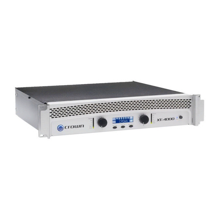
  9. Crown CDi2 600 Installation and operating instructions

Crown CDi2 600 Installation and operating instructions

1
Crown CDi 2 | 600 Amplifier Addendum
OVERVIEW
This guide provides instructions on how to setup and congure a Crown CDi2 | 600
amplier and landscape speaker system.
CONTENTS
• 1x Crown CDi2 | 600 amplier
• 1x Amplier addendum
• 5 x Spade Lugs
• 2 x 6-Conductor Audio Input Phoenix Connectors
• 5 x Rack Screws
• 1 x 8-Conduct GPIO/Aux Phoenix Connector
• 1 x Power Cord
CALCULATING AMPLIFIER POWER
The Crown CDi 2 | 600 has two modes of operation and can be used to drive both low
impedance and high impedance speakers on separate channels, simultaneously.
In low impedance mode the total combined speaker load on the amplier cannot be lower
than 2Ω per channel (4 x 8Ω speakers wired in parallel)
In high impedance mode (70V/100V) the total number of speakers that can be driven by
the amplier is determined by the total available amplier power per channel and the
total combined sum of each speakers tap settings per channel. To determine the total
combined load on the amplier, use this chart:
For 70V/100V installations, we recommend leaving 20% of additional headroom (using
only 80% of the rated power of the amplier). For the Crown CDi 2| 600 this would be
600W X 80% = 480W
Speaker Tap
Setting (A) Ch1 Qty (B) CH2 Qty (C) Ch1 Total
(A x B)
Ch2 Total
(A x C)
3.75W
7.5W
15W
30W
Sub Total
Total Watts
2
INPUT WIRING
Balanced wiring provides better rejection of unwanted noise and hum, however,
unbalanced line may also be used. To wire your source to the amplier use the supplied
male connectors.
NOTE:
When using a subwoofer, it MUST be wired to Output 1 of the Crown CDi 2|600 Amplifier
NOTE:
Burial-rated wire is recommended for all installations.
Figure 1: Unbalanced Wiring Figure 2: Balanced Wiring
SPEAKER WIRING
Low Impedance 8Ω Wiring
For Maximum Performance:
• For wire distances up to 100 ft / 30M, 16-gauge wire or larger is recommended.
• For wire runs up to 200 ft / 60M, 14-gauge wire or larger is recommended.
• For wire runs up to 300 ft /91M, 12-gauge wire or larger is recommended.
Smaller wire gauges may be used, but overall performance will be reduced depending on
the wire gauge used. The chart below shows the wire length and the amount of signal loss
that you can expect on a typical run.
Wire
Gauge
8 Ohm Speakers 4 Ohm Speakers
(Or Two 8 Ohm Speakers in Parallel)
11%
Power Loss
21%
Power Loss
37%
Power Loss
11%
Power Loss
21%
Power Loss
37%
Power Loss
12 291 ft
88.7 m
622 ft
189.6 m
1352 ft
412.1 m
143 ft
43.6 m
331 ft
100.9 m
680 ft
207.3 m
14 189 ft
57.6 m
403 ft
122.8 m
876 ft
267 m
92 ft
28 m
199 ft
60.6 m
437 ft
133.2 m
16 117 ft
35.6 m
225 ft
68.6 m
553 ft
168.5 m
61 ft
18.6 m
128 ft
39 m
278 ft
84.7 m
18 87 ft
26.5 m
194 ft
59.1 m
405 ft
123.4 m
41 ft
12.5 m
92 ft
28 m
201 ft
61.3 m
INPUT
SOURCE
INPUT
SOURCE
3
High Impedance 70V/100V Wiring
One of the advantages of 70V systems is that a smaller wire gauge can be used with lower
power loss. A 20ga cable can be used for up to 1,147 feet with only an 11% power loss.
An 18ga cable can be used for up to 2,029 feet and a 16ga up to 2,783 feet.
NOTE:
Burial-rated wire is recommended for all outdoor installations.
CHOOSING THE CORRECT DEVICE PRESET
The Crown CDi 2 | 600 amplier is pre-loaded with speaker tunings that have been
specically designed for landscape speakers to help make installations quicker and easier.
We do not recommend mixing the 4” and 6” Landscape speakers on the same amplier
channel as custom speaker settings cannot be properly enabled.
NOTE:
If you are using a subwoofer in your installation, it MUST be connected to Output 1.
NOTE:
It is not recommend mixing 4” and 6” speaker on the same Output as custom device
presets cannot be loaded.
(REFER TO DEVICE CHART ON NEXT PAGE)
LOADING DEVICE PRESETS
To load a device preset from the amplier front panel:
1. From the Home screen, press the MENU button.
2. Select the “Congure Amplier” option from the menu using the ENCODER.
3. Select the “Load Preset” option.
4. Use the ENCODER to navigate presets using the on-screen “PREV” and “NEXT”
buttons. As each preset is selected, the preset number, name, and conguration will
be displayed on-screen.
5. Once the desired preset has been selected, use the ENCODER to select “LOAD”.
4
Technical Support: 1-800-448-0976
Copyright © 2018 Nortek Security and Control. All Rights Reserved
P/N: 10021514 - Rev-A0
DEFAULT DEVICE FILE
Preset
#
Preset
Name Output (Voltage) Speaker Hookup
Conguration Comments Tap Setting On Satellite
2AW4
Channel 1=70V SAT 4” connected to
Channel 1
1-12 Satellites/Channel
(wired in parallel) 30W or less
13-24 Satellites/Channel
(wired in parallel) 15W or less
Channel 2=70V SAT 4” connected to
Channel 2
25-50 Satellites/Channel
(wired in parallel) 7.5W or less
51-100 Satellites/Channel
(wired in parallel) 3.75W
3AW6
Channel 1=70V SAT 6” connected to
Channel 1
1-12 Satellites/Channel
(wired in parallel) 30W or less
13-24 Satellites/Channel
(wired in parallel) 15W or less
Channel 2=70V SAT 6” connected to
Channel 2
25-50 Satellites/Channel
(wired in parallel) 7.5W or less
51-100 Satellites/Channel
(wired in parallel) 3.75W
4 AW4-6-MIX
Channel 1=70V SAT 4” connected to
Channel 1
1-12 Satellites/Channel
(wired in parallel) 30W or less
13-24 Satellites/Channel
(wired in parallel) 15W or less
Channel 2=70V SAT 6” connected to
Channel 2
25-50 Satellites/Channel
(wired in parallel) 7.5W or less
51-100 Satellites/Channel
(wired in parallel) 3.75W
5AW4-
10SUB
Channel 1=8/4 ohm BURIAL SUB 10”
connected to Channel 1
Maximum 2 subwoofers can be used in
parallel connection 1-12 Satellites (wired in parallel) 30W or less
Front level controls can be used to raise/
lower the subwoofer level (Channel 1) relative
to level of the satellite speakers (Channel 2)
13-24 Satellites (wired in parallel) 15W or less
Channel 2=70V SAT 4” connected to
Channel 2
25-50 Satellites (wired in parallel) 7.5W or less
51-100 Satellites (wired in parallel) 3.75W
6AW6-
10SUB
Channel 1=8/4 ohm BURIAL SUB 10”
connected to Channel 1
Maximum 2 subwoofers can be used in
parallel connection 1-12 Satellites (wired in parallel) 30W or less
Front level controls can be used to raise/
lower the subwoofer level (Channel 1) relative
to level of the satellite speakers (Channel 2)
13-24 Satellites (wired in parallel) 15W or less
Channel 2=70V SAT 6” connected to
Channel 2
25-50 Satellites (wired in parallel) 7.5W or less
51-100 Satellites (wired in parallel) 3.75W
7AW4-
12SUB
Channel 1=8/4 ohm BURIAL SUB 12”
connected to Channel 1
Maximum 2 subwoofers can be used in
parallel connection 1-12 Satellites (wired in parallel) 30W or less
Front level controls can be used to raise/
lower the subwoofer level (Channel 1) relative
to level of the satellite speakers (Channel 2)
13-24 Satellites (wired in parallel) 15W or less
Channel 2=70V SAT 4” connected to
Channel 2
25-50 Satellites (wired in parallel) 7.5W or less
51-100 Satellites (wired in parallel) 3.75W
8AW6-
12SUB
Channel 1=8/4 ohm BURIAL SUB 12”
connected to Channel 1
Maximum 2 subwoofers can be used in
parallel connection 1-12 Satellites (wired in parallel) 30W or less
Front level controls can be used to raise/
lower the subwoofer level (Channel 1) relative
to level of the satellite speakers (Channel 2)
13-24 Satellites (wired in parallel) 15W or less
Channel 2=70V SAT 6” connected to
Channel 2
25-50 Satellites (wired in parallel) 7.5W or less
51-100 Satellites (wired in parallel) 3.75W
98-AW4-10S
Channel 1=8/4 ohm BURIAL 10” connected
to Channel 1
Maximum 2 subwoofers can be used in
parallel connection Maximum 4 Satellites
wired in parallel 8 ohm
Front level controls can be used to raise/
lower the subwoofer level (Channel 1) relative
to level of the satellite speakers (Channel 2)
Channel 1=8/4 ohm SAT 4” connected to
Channel 2
10 8-AW6-10S
Channel 1=8/4 ohm BURIAL SUB 10”
connected to Channel 1
Maximum 2 subwoofers can be used in
parallel connection Maximum 4 Satellites
wired in parallel 8 ohm
Front level controls can be used to raise/
lower the subwoofer level (Channel 1) relative
to level of the satellite speakers (Channel 2)
Channel 1=8/4 ohm SAT 6” connected to
Channel 2
11 8-AW4-12S
Channel 1=8/4 ohm BURIAL SUB 12”
connected to Channel 1
Maximum 2 subwoofers can be used in
parallel connection Maximum 4 Satellites
wired in parallel 8 ohm
Front level controls can be used to raise/
lower the subwoofer level (Channel 1) relative
to level of the satellite speakers (Channel 2)
Channel 1=8/4 ohm SAT 4” connected to
Channel 2
12 8-AW6-12S
Channel 1=8/4 ohm BURIAL SUB 12”
connected to Channel 1
Maximum 2 subwoofers can be used in
parallel connection Maximum 4 Satellites
wired in parallel 8 ohm
Front level controls can be used to raise/
lower the subwoofer level (Channel 1) relative
to level of the satellite speakers (Channel 2)
Channel 1=8/4 ohm SAT 6” connected to
Channel 2
13 8-AW4
Channel 1=8/4 ohm SAT 4” connected to
Channel 1 Maximum 4 Satellites wired in
parallel on each channel 8 ohm
Channel 1=8/4 ohm SAT 4” connected to
Channel 2
14 8-AW6
Channel 1=8/4 ohm SAT 6” connected to
Channel 1 Maximum 4 Satellites wired in
parallel on each channel 8 ohm
Channel 1=8/4 ohm SAT 6” connected to
Channel 2
Use this chart to select the preset that is appropriate for the system. The Output 2 column shows the
speaker and appropriate preset to use based on the speakers connected to Output 1.
Other Crown Amplifier manuals

Crown PSA-2 User manual

Crown

Crown PSA-2 User manual

Crown XS500 User manual

Crown

Crown XS500 User manual

Crown DSi 1000 User manual

Crown

Crown DSi 1000 User manual

Crown ce 4000 Manual

Crown

Crown ce 4000 Manual

Crown Com-Tech CT-400 Quick start guide

Crown

Crown Com-Tech CT-400 Quick start guide

Crown 280A User manual

Crown

Crown 280A User manual

Crown Studio Reference I Manual

Crown

Crown Studio Reference I Manual

Crown I-Tech I-T5000 HD User manual

Crown

Crown I-Tech I-T5000 HD User manual

Crown CL4 User manual

Crown

Crown CL4 User manual

Crown VRACK User manual

Crown

Crown VRACK User manual

Crown PowerTech PT 3.1 User manual

Crown

Crown PowerTech PT 3.1 User manual

Crown PL-4 User manual

Crown

Crown PL-4 User manual

Crown PL-4 Quick start guide

Crown

Crown PL-4 Quick start guide

Crown PSA-2 Manual

Crown

Crown PSA-2 Manual

Crown MRX-12S User manual

Crown

Crown MRX-12S User manual

Crown DSi 2000 User manual

Crown

Crown DSi 2000 User manual

Crown PSA-2 User manual

Crown

Crown PSA-2 User manual

Crown DC 300 User manual

Crown

Crown DC 300 User manual

Crown XLS 1000 Series User manual

Crown

Crown XLS 1000 Series User manual

Crown D-75 User manual

Crown

Crown D-75 User manual

Crown DC-300A II User manual

Crown

Crown DC-300A II User manual

Crown I-T12000 HD User manual

Crown

Crown I-T12000 HD User manual

Crown XLi 3500 User manual

Crown

Crown XLi 3500 User manual

Crown K1 User manual

Crown

Crown K1 User manual

Popular Amplifier manuals by other brands

Outlaw 970 owner's manual

Outlaw

Outlaw 970 owner's manual

Origin Effects Cali76 instructions

Origin Effects

Origin Effects Cali76 instructions

For-x MAESTRO-812DSP-DSD owner's manual

For-x

For-x MAESTRO-812DSP-DSD owner's manual

Art TPS II user guide

Art

Art TPS II user guide

Fishman PREFIX PLUS manual

Fishman

Fishman PREFIX PLUS manual

Peavey Bandit 112 user guide

Peavey

Peavey Bandit 112 user guide

Canor PH 2.10 user manual

Canor

Canor PH 2.10 user manual

WatchNet AVCNAB quick guide

WatchNet

WatchNet AVCNAB quick guide

Yamaha AX-10 owner's manual

Yamaha

Yamaha AX-10 owner's manual

iPA IPA-P8C Operation manual

iPA

iPA IPA-P8C Operation manual

Rocktron Velocity 100 user guide

Rocktron

Rocktron Velocity 100 user guide

Omnitronic E-Series user manual

Omnitronic

Omnitronic E-Series user manual

Krell Industries Evolution Owner's reference

Krell Industries

Krell Industries Evolution Owner's reference

Jabra GN 8000-MPA Specifications

Jabra

Jabra GN 8000-MPA Specifications

Mobridge DA-G2 A2B FORD manual

Mobridge

Mobridge DA-G2 A2B FORD manual

HP HP-7035B Technical manual

HP

HP HP-7035B Technical manual

Rockford Fosgate T2500-1bd CP Installation & operation

Rockford Fosgate

Rockford Fosgate T2500-1bd CP Installation & operation

moon 330A owner's manual

moon

moon 330A owner's manual

manuals.online logo
manuals.online logoBrands
  • About & Mission
  • Contact us
  • Privacy Policy
  • Terms and Conditions

Copyright 2025 Manuals.Online. All Rights Reserved.