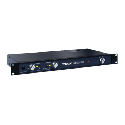
Crown D-150A User manual

croiun
SERVICE MANUAL
D-150A POWER AMPLIFIER
CROWN INTERNATIONAL, INC. 1718 W. MISHAWAKA RD. ELKHART, INDIANA 46517
©1988 Crown International, Inc.
K30028-2
1/83


crown
RVW Sec.
Section 6
Section 7
Section 8
TABLE OF CONTENTS
Review
I. Introduction .......
II. Warranty
III. Specifications .....
IV. Panel Configuration
V. Performance Graphs
Illustrated Parts List
6.1 General Information
6.2 Standard and Special Parts
6.3 Ordering Parts
6.4 Shipment
6.5 Terms
6.6 Schematics/ Parts Lists/ Exploded View Drawings
Maintenance
7.1 Introduction
7.2 Required Test Equipment
7.3 Soldering Techniques
7.4 Basic Troubleshooting
7.5 Discharging Instructions
7.6 Disassembly for Inspection, Service, Testing, Adjustment and Repairs
7.7 Reassembly
7.8 Electrical Checkout and Adjustment Procedures
7.9 Troubleshooting Hints
7.10 Voltage Conversion Chart
7.11 Block Diagram Circuit Theory
7.12 Theory of Operation
Service Bulletins
6-1
6-1
6-1
6-1
6-1
6-2
.7-1
.7-1
.7-2
.7-7
.7-8
.7-8
7-10
7-10
7-12
7-15
7-16
7-17
.8-1

LIST OF ILLUSTRATIONS
Fig. RVW.l
Fig. RVW.2
Fig. RVW.3
Fig. RVW.4
Fig. RVW.5
Fig. RVW.6
Fig. RVW.7
Fig. RVW.8
Fig. RVW.9
Fig. RVW.10
Fig. RVW.l 1
Fig. 6.1
Fig. 6.2
Fig. 6.3
Fig. 6.4
Fig. 6.5
Fig. 6.6
Fig. 6.7
Fig. 6.8
Fig. 6.9
Fig. 6.10
Fig. 6. 1
1
Fig. 6.12
Fig. 6.13
Fig. 6.14
Fig. 6.15
Fig. 6.16
Fig. 6.17
Fig. 6.18
Fig. 6.19
Fig. 7.1
Fig. 7.2
Fig. 7.3
Fig. 7.4
Fig. 7.5
Fig. 7.6
Fig. 7.7
Fig. 7.8
Fig. 7.9
Fig. 7.10
Fig. 7. 1
1
Fig. 7.12
Fig. 7.13
Fig. 7. 14
Fig. 7.15
Fig. 7.16
Fig. 7.17
Fig. 7.18
Fig. 7.19
Fig. 7.20
Fig. 7.21
Fig. 7.22
Fig. 7.23
Fig. 7.24
Fig. 7.25
Fig. 7.26
Fig. 7.27
Fig. 7.28
D-150A Front Panel
D-150A Rear Panel
Nominal Frequency Response .........
Nominal Phase Response .............
Nominal Crosstalk
Nominal Noise Sepectrum
Nominal Output Impedance
Nominal Output Phase Angle
Nominal Damping Factor (8 ohms) ....
Nominal Power Efficiency ............
V-I Plot
MI-261 Main Board Schematic
MI-261 Foil Board Layout
MI-261 AMain Board Schematic ......
MI-261 AFoil Board Layout ..........
MI-261 BMain Board Schematic
.
MI-261 BFoil Board Layout
MI-26 1C Main Board Schematic
MI-26 1C Foil Board Layout
MI-261 DMain Board Schematic
MI-261 DFoil Board
MI-261 EMain Board Schematic
MI-26 IE Component Board Layout
MI-261 EFoil Board Layout
IOC Component Board Layout
IOC Foil Board Layout
Front Panel Assembly
Chassis Assembly
Output Assembly
Miscellaneous Assembly
Miniature Soldering Iron
Correct and Incorrect Solder Application
Unsoldered Wire
External Strands
Cut Strands
Wire Strippers
Disturbed Joint
Cold Solder Joint
Rosin Joint
Component Lead Spacing
Component Lead Bending
Correct Pressure Applied
Acceptable Solder Joints
Soldering to aLug
Turret Terminal ......................
Wire Braid Desoldering ...............
Discharge Points
IM Distortion Test Set-up
Signal to Noise Test Set-up ............
Voltage Conversion ...
D-150A Block Diagram
Input Stage
Voltage Amplification Stage
Output Stage
Protection Circuitry Stage
Bootstrap Supply
IOC Stage
World-Wide Voltage Map ..... ....
.R-3
.R-3
.R-4
.R-4
.R-5
.R-6
.R-6
.R-6
.R-7
.R-7
.R-8
..6-2
..6-2
..6-4
..6-5
..6-6
..6-7
..6-8
..6-9
.6-10
.6-11
.6-12
.6-12
,6-13
.6-13
.6-13
,6-16
6-17
6-
19
6-21
.7-2
.7-3
.7-3
.7-4
.7-4
.7-4
.7-5
.7-5
.7-6
.7-6
.7-6
.7-6
.7-6
.7-7
.7-7
.7-7
.7-8
7-
11
7-12
7-15
7-16
7-17
7-17
7-18
7-18
7-19
7-19
7-20

crown
REVIEW SECTION
I. Introduction
This manual contains complete service information on
the D- 150A. It is designed to be used in conjunction with
the D- 150AInstruction Manual. However, some
important information is duplicated in this Service
Manual in case the Instruction Manual is not readily
available.
NOTE: THE INFORMATION IN THIS MANUAL
IS INTENDED FOR USE BY AN EXPERIENCED
TECHNICIAN ONLY!
II. Warranty
As aCrown Warranty Service Station, you should be
familiar with Crown warranty policies. Each Instruction
Manual contains basic policies as related to the customer.
However, under questionable circumstances, please
contact the Technical Service Department or Director of
Customer Service at: Crown International, Inc., 1718
W. Mishawaka Road, Elkhart, IN 46517.
III. Specifications
General Specifications
Hum and Noise (20Hz-20KHz): HOdB below rated
output.
Phase Response: +0, -15°, DC-20KHz at 1watt.
Input Impedance: 25K ohms, ±3%.
Amplifier Output Protection: Short, mismatch, and
open circuit proof. Limiting is instantaneous with no
flyback pulses, thumps, cutouts, etc. No premature
limiting on transients.
Overall Protection: AC line fused. Thermal switch in AC
line protects against overheating caused by insufficient
ventilation. Controlled slewing-rate voltage amplifiers
protect overall amplifier against RF burnouts. Input
overload protection is furnished by internal resistance at
inputs of amp.
DC Output Offset (Shorted Input): 10 millivolts or less,
internally adjustable to zero.
Turn-On: Instantaneous, with minimum thumps and no
program delay.
Circuit: Wideband multiple feedback loop design
utilizing one linear IC (dual op-amp), total equivalent of
48 transistors, 22 signal diodes, 3zener diodes, and 6
rectifier diodes.
Power Supply: Massive computer-grade filter
capacitors store over 20 joules of energy. Two regulated
supplies for complete isolation and stability.
Power Requirements: Requires 50-400Hz AC on H)0,
200, 220, or 240V ±10% operation. Draws 30 watts or less
on idle, 250 watts at 160 watts total output.
Heat Sinking: The entire amplifier is used as aheat sink.
3/16 inch thick chassis acts as aheat sink along with
auxiliary fins.
Chassis: All aluminum construction for maximum heat
conduction and minimum weight.
Controls: Independent level controls are mounted on the
front panel. Power switch with associated pilot light is on
front panel. Non-interacting DC balance controls are
mounted on main PC board under electronics cover. A
mono-stereo switch is located next to the input jacks on
the rear panel.
Connectors: Input -'A inch phone jacks, output -color
coded binding posts, AC line -3-wire (grounded) male
connector on 5foot minimum cable.
Dimensions: 17 inches (43.18cm) long, 5!4 inches
(13.34cm) high, 8% inches (22.23cm) deep (from
mounting surface of front panel), 19 inches (48.26cm)
long with standard rack mounting brackets installed.
Weight: 24 pounds.
Finish: Satinized aluminum front panel with gray suede
Lexan insert.
Stereo Specifications
Output Power: 80 watts per channel minimum RMS
(both channels operating) into an 8ohm load over a
bandwidth of 1Hz-20KHz at arated RMS sum total
harmonic distortion of 0.05% of the fundamental output
voltage.
Frequency Response: ±0. 1dBDC-20KHzat 1watt into 8
ohms; ±ldB DC-lOOKHz.
IKHz Power: 90 watts RMS into 8ohms, per channel,
both channels operating, 0. 1% total harmonic distortion.
Harmonic Distortion: Less than 0.001% from 20-400 Hz
and increasing linearly to 0.05% at 20KHz at 80 watts
RMS per channel into 8ohms.
LM, Distortion S.M.P.T.E. (60Hz-7KHz 4:1): Less than
0.05% from 0.01 watt to 0.25 watts and less than 0.01%
from 0.25 watts to 80 watts into 8ohms, per channel.
Slewing Rate: 6volts per microsecond (slewing rate is
the maximum value of the first derivative of the output
signal, or the maximum slope of the output signal).
Damping Factor: Greater than 400, DC-400Hz into 8
ohms.
Output Impedance: Less than 15 milliohms in series with
less than 3microhenries.
Load Impedance: Rated for 8ohm usage; safely drives
any load including completely reactive loads.
Voltage Gain: 20.6 ±2% or 26.3±2dB at maximum gain.
Input Sensitivity: 1.19 volts ±2% for 80 watts into 8
ohms.
Output Signal: Unbalanced, dual channel.
Monaural Specifications
Output Power: 160 watts minimum RMSintoa 16ohm
load over abandwidth of lHz-20KHz at arated RMS
sum total harmonic distortion of 0.05% of the
fundamental output voltage.
Frequency Response (IKHz Power): ±0.15dB DC-
20KHz at 1watt into 16 ohms; ±ldB DC-60KHz, 180
watts RMS into 16 ohms.
Harmonic Distortion: Less than 0.001% from 20-400Hz
and increasing linearly to 0.05% at 20KHz at 160 watts
into 16 ohms.
LM. Distortion S.M.P.T.E. (60Hz-7KHz 4:1): Less than
0.05% from 0.01 watts to 0.25 watts and less than 0.01%
from 0.25 watts to 160 watts into 16 ohms, per channel.
Slewing rate: 12 volts per microsecond.
Damping Factor: Greater than 400, DC-400Hz into 16
ohms.
Output Impedance: Less than 30 milliohms in series with
less than 6microhenries.
Load Impedance: Rated for 16 ohm usage; safely drives
any load including completely reactive loads.
Voltage Gain: 41.2 ±2% for 160 watts into 16 ohms.
Input Sensitivity: 1.19 volts ±2% for 160 watts into 16
ohms.
Output Signal: Balanced, single channel.
R-2

©
crown
Fig. RVW.l D-150A Front Panel
A,
B.
c.
D.
E.
CHANNEL 1IOC INDICATOR
CHANNEL 2IOC INDICATOR
CHANNEL 1INPUT LEVEL CONTROL
CHANNEL 2INPUT LEVEL CONTROL
ON/OFF SWITCH
Fig. RVW.2 D-150A Rear Panel
F. MONO/STEREO SWITCH
G. CHANNEL 2UNBALANCED INPUT
H. CHANNEL 1UNBALANCED INPUT
I. AC POWER LINE
J. FUSE HOLDER
K. CHANNEL 2MAIN OUTPUT JACK
L. CHANNEL 1MAIN OUTPUT JACK
R-3

V. Performance Graphs
DS
Idb
Odb
-Idb
2db
mmm FREQutNQ RES!
MM
:
PON!
16 ohm load
8ohm load
4ohm load
,1Hz 1Hz 10Hz 100Hz IKHz lOKHz lOOKHz
Fig.RVWJ Nominal Frequency Response
Fig. RVW.4 Nominal Phase Response
R-4

croujn
Fig. RVW.5 Nominal Crosstalk
Fig. RVW.6 Nominal Noise Spectrum

100Hz IKHz lOKHz lOOKHz
Fig.RVW.7 Nominal Output Impedance
(degrees)
lOKHz lOOKHz
Fig.RVW.8 Nominal Output Phase Angle

cfQtun
lOOKHz
lOKHz
IKHz
100Hz
Fig. RVW.9 Nominal Damping Factor
(8 ohms)
lOOKHz
lOKHz
100Hz
Fig,RVWAO Nominal Power Efficiency

Max. cont AC power
Za=3 ohms
AC line fuse blows (DC
single ch. )
if both ch. driven
equally fuse blows at
half value given
XXShort circuit cont. limit
Max. AC limit (Zl Vout
(sine) at max.)
Fig. RVW.Il V- 1Plot
R-8

crown
SECTION 6
ILLUSTRATED PARTS LIST
6.1 General Information
Section 6contains illustrations and parts lists for the D-
150A. This information should be used with the service,
repair and adjustment procedure in Section 7.
Most of the mechanical and structural type parts are
illustrated and indexed on exploded view drawings.
Electrical and electronic parts on these illustrations are
also identified by the circuit reference designation next to
the illustration. Both the index number and the reference
designation are included in the parts list in separate
columns. The reference designations correspond to those
shown in schematic diagrams in the Review Section.
Electrical and electronic parts located on printed circuit
boards are illustrated by schematic symbols on the trace
side and by component shape symbols on the component
side. Reference designations also appear on these
diagrams.
The quantity of each part used in each location is also
shown in the parts listing.
6.2 Standard and Special Parts
Many electrical and electronic parts used in the D-150A
are standard items stocked by and available from
electronic supply houses. However, some electronic parts
that appear to be standard, are actually special. Apart
ordered from Crown will assure an acceptable
replacement. Structural items, covers and panels are
available from Crown only.
6.3 Ordering Parts
When ordering parts, be sure to give the amplifier model
and serial number and include the part description and
Crown Part Number (CPN) from the parts list. Price
quotes are available upon request.
6.4 Shipment
1. Shipment will be made by UPS or best method unless
you specify apreferred method.
2. Shipments are made F.O.B. Elkhart, Indiana only.
3. Established Crown accounts will be freight prepaid
and billed unless shipped by truck or air freight.
4. All others will be shipped freight collect.
6.5 Terms
1. Normal terms are C.O.D. unless the order is prepaid.
2. Net 30 days terms apply only to those firms who have
an established line of credit with Crown.
3. If prepaying please add an amount for the freight
charge. $1.00 is average for an order under one pound.
NOTE: Part prices are subject to change without
notice.
4. New parts returned for credit are subject to a10%
restocking charge.
5. You must receive authorization from the Parts Dept,
before returning parts for credit.
6. We are not ageneral parts warehouse! Parts are
available for servicing Crown products only.
6-1


Schematic
Designation Description
Crown
Part No. Qty. Other Information
Capacitors
Cl 00, C200,
Cl 06, C206 100pF Mica C3410-5 4
C101, C201 ,00 ImF 200V Filmatic C3480-8 2
Cl 02, C202,
C103, C203,
Cl 14, C214,
C107, C207 200pF Mica C3411-3 8
Cl 04, C204,
Cl 17, C217 47pF Mica C3409-7 4
C105, C205 120pF Mica C3290-1 2
C108, C208,
C109, C209 22mF 50V Vertical C5311-3 4
C110, C210 .0027mF 200V Filmatic C3481-6 2
Clll, C21
1
470pF Mica C2511-1 2
Cl 12, C212 .0022mF 200V Filmatic C3285-1 2
Cl 13, C213, C6 .OlmF Ceramic Disc C1751-4 3
Cl 15, C215 0.22mF 100V Filmatic C3218-2 2
Cl 16, C216,
Cl, C8 .ImF 200V Filmatic C2938-6 4
C2, C3 9400mF 50V C3309-9 2
C4 lOmF 160VC2796-8 1
C5 lOmF 50V Vertical C3728-0 1
C7 lOOmF 16V Vertical C3729-8 1
C9 .00 ImF Ceramic Disc C2288-6 1
R100, R200
Resistors
100K Horizontal Pot C1709-2 2Output offset adjust
R101, R201 2M ohm .25W 5% CF C3199-4 2
R102, R202 250K Horizontal Pot C3087-1 2Input offset adjust
R104, R204 820K ohm .25W 5% CF C3623-3 2
R105, R205 25K ohm Audio Pot D2942-7 2
R106, R206 4.7K ohm .25W 5% CF C3939-3 2
R107, R207 56 ohm .25W 5% CF C3511-0 2
R108, R208 3.3K ohm .25W 10% 2629 2Used when IC-1 is UA749.
R109, R209 510 ohm .5W 1% MF C3304-0 2
See IC-1 under integrated
circuits.
R110, R210 2.4K ohm .25W 5% CF C3616-7 2
Rill, R21
1
56K ohm .25W 5% CF C2882-6 2
R1 1 2, R212, R5 8.2K ohm .25W 5% CF C2877-6 3
R1 1 3, R213 5.6K ohm .25W 5% CF C3220-8 2
R114, R214,
R103, R203 IK ohm .25W 5% CF C2627-5 4
R115, R215, Rll 10K ohm .5W 1% MF C2343-9 3
R116, R216 820 ohm .25W 5% CF C3301-6 2
R1 1 7, R217 33K ohm .5W 5% MF C3137-4 2
R1 1 8, R218,
R123, R223 120 ohm .5W 5% CF C3837-9 4
R119, R219,
R122, R222,
R124, R224 82 ohm .25W 5% CF C3960-9 6
Parts List:D-150A Main Module (For SN26591 and above)
Schematic
Designation Crown
Part No
Description Qty. Other Information
R120, R220 5. IK ohm 1W 5% MF C2808-1 2
R121, R221 27K ohm ,5W 5% CF C1056-8 2
R125, R225, R2 2.2K ohm ,5W 5% CF C1036-0 3
R126, R226 750 ohm .25W 5% CF C3803-1 2
R127, R227 15 ohm .25W 5% CF C3614-2 2
R128, R228 -Selected- —2Bias resistors
R129, R229, R13
R130, R230,
47 ohm .25W 5% CF C1011-3 3
R135, R235
R131, R231,
180 ohm .25W 5% CF C2873-5 4
R136, R236
R132, R232,
5.6 ohm ,5W 5% CF C3299-2 4
R134, R234 0.1 ohm 5W 10% C4761-0 4
R133, R233 2.7 ohm 1W 10% C1001-4 2
R137, R237 180K ohm ,2W 5% CF C4218-1 2
R3 1.5K ohm 2W 10% C3303-2 1
R4, R17 200K ohm. 25W 5% CF C3622-5 2
R6 91 Kohm .25W 5% CF C3621-7 1
R7 6.2K ohm .25W 5% CF C3619-1 1
R8 2.7K ohm 1W 10% C1079-0 1
R9 1ohm ,5W 5% CF C3612-6 1
R10 390 ohm ,5W 5% CF C2609-3 1
R12
R142, R242,
390 ohm 2W C4029-2 1
R143, R243
R145, R245,
13K ohm .25 W5% CF C4300-7 4
R146, R246
Q100, Q200,
Q104, Q204,
2.7 ohm .5W 5% CF
Transistors
C2857-8 4
Q108, Q208 2N4125 PNP C3625-8 6
Q10 1,Q201, Q2 PN4250A PNP C3786-8 3
Q101, Q201
Q102, Q202,
Q103, Q203,
Q106, Q206,
MPS93 PNP C3578-9 2
Qlll, Q21 1, Q1 SEL 2N3859 NPN D2961-7 7
Q105, Q205 MPSL01 NPN C3232-3 2c:S'
Positive predrivers
Q107, Q207 NSD106 NPN C4069-8 —2
Q109, Q209 SEL 2N3585 NPN D3295-9 2Drivers
Q112, Q212 SS7304 PNP D5611-5 QJVJ-i 2Negative predriver
Q1 13, Q213 SEL 2N3585 NPN
*No longer available
QUO, Q210
D3295-9 2Negative driver
Q114, Q214
QUO, Q210,
2N3773 *3773 4Used with D-150A SN
8359 and below
Q114, Q214
QUO, Q210,
2N5631 *3991 4Used with D-150A between
SN8360 and 17875
(selected units)
Q114, Q214
QUO, Q120,
T6J0377 *3941 4Used with D-150A between
SN8360 and 17875
(selected units)
Q114, Q214 2N5631 100V C3990-6 4Used with D-150A SN
17876 and above 6-14

Parts List: D-150A Main Module (Continued)
Schematic Crown
Designation Description Part No. Qty. Other Information
IC 1A,B
iliicgl <ttvll VII %,U1|3
739PC Dual Op Amp C3231-5 1
Diodes
D100, D200,
D101 , D201,
D103, D203,
D104, D204,
0105, D205 IN4148 C3181-2 10
D102, D202,
D106, D206,
Dl, D2 IN4004 C2851-1 6
D107, D207 IN270 C3447-7 2
D3, D4, D5 IN961B 10V Zener C3549-0 3
Miscellaneous
2Conductor Jacks C3423-8 2Input jacks
SW2 A-P Switch M20 105-9 1On/ off
SW3 DPDT Slide Switch C4110-0 1Stereo/ Mono
LI 00, L200
14 PIN IC Socket
.5mh coil
C3450-1
C3510-2
1
2
Parts List: D-150A IOC Module (SN22394 and above)
Capacitors
Cl 18, C218
C8
R138, R238
R139, R239
R140, R240
R141, R241
R14, R16
R15
R144, R244
Q115, Q215,
Q116, Q216
IC2A,B,C,D
0.22mF 100V Filmatic
2.2mF 50V Vertical
Resistors
1.6M .25W 5% CF
2.7K ohm 1W 10%
27 Kohm ,5W 5% CF
18K ohm .25W 5% CF
33K ohm ,25W 5% CF
150K ohm ,25W 5% CF
10K. ohm ,25W 5% CF
Transistors
Selected 2N3859A NPN
LM 339 Voltage Comparator
Diodes
1N4148
MV5053 Red LED
Miscellaneous
C3218-2
C5362-6
C4235-5
C1079-0
C1056-8
C2633-3
C4346-0
C4216-5
C2631-7
D2961-7
4345
C3181-2
C4341-1
Parts List: D-150A Front Panel Assembly
Index Schematic
No. Designation Description Crown
Part No. Qty. Other Information
i.83 Aluminum Knob D4075-4 3
2.375 Bright Nut C1288N7 3
3.625x.375x.030 Brightwasher C2189-6 3
4Front Panel Lexan Insert D4091-1 1
5D-150A Front Panel D4614-0 1
65.25 Rack Mount Ears F9787-7 2^Optional; end-bar also
supplied
7S632 .75 Machine Screw C1858-7 4
8Lamp Bracket F9598-8 I
910-32 Hex Nut C2170-6 1
10 #10 Internal Starwasher C2279-5 1
|ill End Cover (Transformer Side) F9565J6 I
12 T10 32 .50 Machine Screw 2049N-2 4
13 Transformer Wraparound F9952J6 1
14 Transformer Cover D3355-1 1
15 T10 32 .50 Machine Screw 2049N2 2
16 Heatsink Fin na
17 Board Cover Oj7jO“0
F9564J
9
Z
l
18 End Cover (Board Side) F9566J4 l
19 Chassis D3544-0 l
2D SW 10 P. 75 Self-tapping Screw C4017-7 4
12l IOC Board Module M41904-0 1
12? #6 Internal Starwasher C5594-4 2
12B. 6-32 Hex Nut C1889-2 2
12p .250x. 141x.625 Aluminum Spacer C4612-5 2
125 #10 Internal Starwasher C2279-5 2
26 X632 1.0 Machine Screw C4333-8 2
27 R106, R206 25K ohm Audio Pot D2942-7 2
28 334 Solder Lug .375 Hole D2828-8 2
29 .375 Internal Starwasher C2188-8 7
30 R6 32 .25 Machine Screw C1954-4 6
31 #6 Internal Starwasher C5594-4 6
32 SW2 Rotary Power Switch M41549-3 1
jUVf »rj§«U3 ~
cA
i
CZJoo 1
14 PIN IC Socket C3450-1


70 72
6-17 Fig. 6.17 Chassis Assembly

Parts List: D-15QA Chassis Assembly
Inde*
No.
Schematic
Designation Description
Crown
Part No. Qty. Other Information
33 T8 32 .25 Machine Screw C2271-2 2
34 Dress Plate F9594J6 1
35 .375 Bright Nut C1288N7 2
36 .625x.375x.030 Bright Washer C2189-6 2
37 .625x.375x.015 Fiber Washer C1646-6 2
38 .375 Fiber Shoulder Washer C1306-7 2
39 2Conductor Phone Jack C3423-8 2
40 Jack Plate F9595J3 1
41 SW3 DPDT Slide Switch C4110-0 1
42 F8-32 .23 Machine Screw C2136-7 2
43 Hex Standoff D3961-6 2
44 Solder Lug #8 Hole D2935-1 2
45 6-32 Hex Nut C1889-2 19
46 #6 Internal Starwasher C5594-4 19
47 Board Mount Bracket F9562-4 1
48 Dual Binding Post C2823-0 2
49 SPSTNC Thermal Switch C2799-2 1
50 505 Solder Lug #6 Hole D3163-9 8Misc. use
51 R6 32 .62 Machine Screw C3879-1 2
52 8-32 Hex Nut C1986-6 2
53 .875x. 187 Fiber Washer D3669-1 4
54 Output Inductor Assembly M40959-5 2
55 Solder Lug #8 Hole D2935-1 1
56 8-32x1.75 Stud Screw C3324-8 2
57 F2 MDX 7Amp Fuse C4385-8 1
58 Fuse Block C3776-9 1
59 Pressure Sensitive Tape S1152-8 -
60 T10 32 .50 Machine Screw C2049N2 4
61 #10 Internal Star Washer C2279-5 8
62 389 Solder Lug .218 Hole D2934-4 4
63 .625x.234x.047 Steel Washer C4917-8 4
64 5-16 Fiber Shoulder Washer C3320-6 4
65 .730x.525x. 187 Nylon Washer C1657-3 4
66 MDA 3502 35A Bridge C4305-6 1
67 R6 32 1.00 Machine Screw C2138-3 1
68 2-G-l Terminal Strip D3323-9 2
69 3H2A Terminal Strip D5366-6 1
70 10-32 Hex Nut C2170-6 4
71 #10 Internal Star Washer C2279-5 8
72 T10 32 .50 Machine Screw C2049N2 4
73 LI Lamp 1822 36V .1
A
C2900-6 1On/ off indicator
74 Lamp Bracket F9598-8 1
75 T1 D-150A Power Transformer D4380-8 1
76 C2, C3 9, 400mF50V C3309-9 2
77 3-18 Power Cord H40960-9 1
78 HTA Fuseholder C3256-2 1
79 FI MDX 6.25 Amp Fuse C4307-2 1
80 R6 32 .37 Machine Screw C2134C6 1
81 Grommet .375 Grooved C1566-6 6
82 #8 Type Plain Washers C2101-1 6
6-18

Other manuals for D-150A
3
Other Crown Amplifier manuals

Crown
Crown CTs 1200 Parts list manual

Crown
Crown I-Tech I-T4000 User manual

Crown
Crown Vrack 4x3500 User manual

Crown
Crown Macro-Tech MA-10000 User manual

Crown
Crown XLS 402 User manual

Crown
Crown CTs 1200 User manual

Crown
Crown CDi 2000 User manual

Crown
Crown PS-200 User manual

Crown
Crown CROWN K Series User manual

Crown
Crown Studio Reference I User manual

Crown
Crown D-150A Series II User manual

Crown
Crown CL1 User manual

Crown
Crown CTs 4200 USP/CN User manual

Crown
Crown CTs 4200 USP/CN User manual

Crown
Crown PSA-2 User manual

Crown
Crown CTs 4200 User manual

Crown
Crown CE 2000 Manual

Crown
Crown D-75 User manual

Crown
Crown Micro-Tech MT-1000 User manual

Crown
Crown Geodyne I Quick start guide