CRS A255 User manual

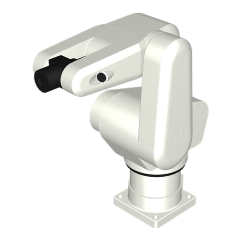
A255 Robot Arm
User Guide
For use with C500C Controller
UMI-33-255-A

ii
Revision History
Number Details Date
001 Original issue as A255 for C500C.
Updated to CROS 1.16. 99-05
Copyright © 1999 CRS Robotics Corporation
RAPL-3 is a trademark of CRS Robotics Corporation and may be used to describe only CRS Robotics products.
Any brand names and product names used in this guide are trademarks, registered trademarks, or trade names
of their respective holders.
The information in this document is subject to change without notice.
CRS Robotics Corporation makes no warranty of any kind with regard to this material, including, but not limited
to, the implied warranties of merchantability and fitness for a particular purpose. CRS Robotics Corporation
assumes no responsibility for any errors that may appear in this document. CRS Robotics Corporation makes no
commitment to update nor to keep current the information contained in this document.
CRS Robotics Corporation assumes no responsibility for the use of any circuitry other than circuitry embodied in
a CRS product.
CRS Robotics Corporation software products shall remain the property of CRS Robotics Corporation.

iii
Preface
This user guide accompanies the A255 robot arm used with the C500C controller.
This Guide
This user guide contains general information, arm specifications, safety
precautions, installation instructions, startup procedures, and basic operation
instructions for the CRS Robotics A255 robot arm.
This A255 User Guide is available in English.
Other Guides
Additional information is available in the following documents.
•C500C Controller User Guide
•Application Development Guide
•RAPL-3 Language Reference Guide
Additional copies of this arm user guide, or other CRS Robotics literature, may be
obtained from your distributor or the CRS Robotics Sales Department.
Training
This installation guide is not intended as a self-teaching tool. It is intended as a
guide for those who have attended a CRS Robotics robot training course and have
a basic knowledge of CRS Robotics robots.
Training courses are offered at our facility in Burlington, Ontario, Canada, or can
be conducted at your facility. For additional information, contact the Customer
Support Group.
Contact
CRS Robotics Corporation
Mail/Shipping:
5344 John Lucas Drive, Burlington, Ontario L7L 6A6, Canada
Telephone:
1-905-332-2000
Telephone (toll free in Canada and United States):
1-800-365-7587
Facsimile:
1-905-332-1114
E-Mail (General):
info@crsrobotics.com
E-Mail (Customer Support):
support@crsrobotics.com
E-Mail (Sales):
sales@crsrobotics.com
E-Mail (Training):
training@crsrobotics.com
Web:
www.crsrobotics.com

iv
E-Mail (Sales):
sales@crsrobotics.com
E-Mail (Training):
training@crsrobotics.com
Web:
www.crsrobotics.com
How to Use This User Guide
This user guide is organized with each chapter covering a different topic.
•If you are installing or using the robot, read the Safety Precautions chapter.
•If you have received a robot for the first time, read the Specifications and
Installation chapter.
•If you are installing the robot yourself, read the Installation and
Commissioning chapter.
•If the robot was installed by CRS or a distributor, read the chapters on
Commissioning and Operation Basics.
Before attempting to follow a procedure or examples, read the entire section first.
Throughout this user guide, warnings are marked by an “!” icon in the left margin.
Failure to comply with these warnings can result in injury to persons; damage to the robot,
tooling, or work pieces; loss in memory; or errors in the system.

v
Contents
Chapter 1 1
Introduction .............................................................................1
Optional Equipment ............................................................2
Chapter 2 3
Specifications ...........................................................................3
Range of Motion, Dimensions, and Weight............................4
Reach .................................................................................6
Torque Ratings....................................................................8
Joint Speeds and Acceleration Rates....................................8
Payload...............................................................................9
Resolution.........................................................................11
Brakes ..............................................................................12
Gripper .............................................................................13
Chapter 3 15
Safety Precautions ..................................................................15
Physical Barriers...............................................................15
Emergency Stops (E-stops) ................................................17
Presence Sensors...............................................................18
Other Safeguards ..............................................................19
Power................................................................................20
Environment.....................................................................21
Robot Handling .................................................................21
Operator Safety.................................................................22
Safety and Operation Checks.............................................23
Working Within the Robot’s Workspace..............................24
Chapter 4 25
Installation.............................................................................25
Required Tools and Supplies..............................................26
Component Parts...............................................................26
Designing a Work Cell .......................................................27
Unpacking the Arm ...........................................................28
Preparing the Mounting Platform.......................................31
Mounting the Arm on the Platform.....................................34
Grounding the Arm ...........................................................34
Connecting the Umbilical Cables........................................35
Next Steps.........................................................................36
Chapter 5 37
Commissioning.......................................................................37
Check the Installation of Arm and Controller......................38
Check the Installation of Other Components......................38
Check Encoder Feedback...................................................39
Check All E-Stops..............................................................40
Move Out of the Shipping Position .....................................41
Check the Live-man Switch ...............................................44
Chapter 6 45
Basic Operation ......................................................................45
Homing the Arm................................................................46
Moving with the Teach Pendant .........................................51
Moving with Terminal Commands......................................52

vi
Moving by Limping One Joint at a Time .............................54
Chapter 7 56
Gripper Installation.................................................................56
Installing the Gripper ........................................................57
Connecting the Cable or Hose............................................58
Chapter 8 61
Calibration .............................................................................61
Restoring Factory Calibration Values .................................62
Recalibrating the Robot Arm..............................................63
Calibrating an Extra Axis...................................................67
Glossary .................................................................................69
Index......................................................................................73

1
99-04-23
CHAPTER 1
Introduction
The A255 arm is articulated with five joints or axes, providing it with five degrees
of freedom. This allows the arm to move a gripper or other tool to cartesian spatial
coordinates and orientation defined by X, Y, Z, Z-rotation, Y-rotation, and X-
rotation.
The A255 robot system consists of an A255 arm and a C500C controller. The
controller runs the CROS-500C operating system and programs written in the
RAPL-3 programming language.
You can operate the A255 by a teach pendant, a terminal, or a RAPL-3 program.
For standard applications, you can edit programs, move the arm, teach locations,
and run programs from either the teach pendant or the terminal.
For advanced applications, you can also edit and compile programs off line on a
computer and use advanced tools through the terminal.
The A255 is designed for laboratory automation, machine loading, product testing,
parts assembling, material handling, education and research, and other tasks.
The A255 arm has five axes of motion (joints): 1 (waist), 2 (shoulder),
3 (elbow), 4 (wrist pitch), and 5 (tool roll).

2 A255 Robot Arm User Guide
99-04-23
Optional Equipment
The following options are available from CRS or an authorized CRS distributor.
End Effectors
•Servo Gripper and Adapter
•Pneumatic Gripper and Adapter
•Microplate Fingers for Servo Gripper
Hardware and Equipment
•Teach Pendant
•Extra-Length Umbilical Cables
•Linear Track
•Remote Operator Panel
•End Effector Custom Cabling
•Homing Bracket
•Force Sensor
•Pressurized Suit
Software
•Robcomm3 (RAPL-3 Program Development Environment and Interface to
C500C)
•POLARA (Laboratory Automation Software)

3
99-04-23
CHAPTER 2
Specifications
This chapter describes the A255 arm:
•Range of Motion, Dimensions, and Weight
•Reach
•Torque Ratings
•Joint Speed and Acceleration Rates
•Payload
•Resolution
•Brakes
•Gripper

4 A255 Robot Arm User Guide
99-04-23
Range of Motion, Dimensions, and Weight
The arm’s range of motion depends on the dimensions of each arm section (base,
links, tool flange) and the extent of travel of each joint. These measurements
determine the shape of the arm’s workspace. See the following figures and tables.
Note: A dimension involving a joint is measured to the joint axis.
The arm weighs approximately 37 lb [17 kg].
Weight (approx.) lb kg
Arm 37 17
Joint Axis Range of Motion
Waist 1 +175°to –175°
Shoulder 2 +110°to 0°
Elbow 3 0°to –125°
Wrist pitch 4 +110°to –110°
Tool roll 5 +180°to –180°
Note: The range of motion of the elbow (joint 3) is dependent on the positions of
the shoulder (joint 2) and the wrist pitch (joint 4).
Section Dimensions
inch mm
Base mounting surface to shoulder 10 254.0
Shoulder to elbow 10 254.0
Elbow to wrist pivot (joint 5) 10 254.0
Wrist pivot to tool flange surface 2 50.8

Chapter 2: Specifications 5
99-04-23
The range of motion of the joints and the dimensions of the sections of the robot
arm.
The 350° range of motion of the waist joint of the robot arm.

6 A255 Robot Arm User Guide
99-04-23
Reach The maximum reach of the arm is calculated horizontally outward from the
shoulder joint (axis 2) and vertically upward from the bottom of the base.
The arm can reach points below the level of the bottom of the base.
A255 Maximum Arm Reach
inch mm
Horizontal to tool flange 22.00 558.8
outward from the shoulder
axis in the X, Y plane to finger platform
of servo gripper 25.78 654.8
Vertical to tool flange 32.00 812.8
upwards along the Z axis to finger platform
of servo gripper 35.78 908.8
Vertical to tool flange 2.00 50.8
downwards below the
base level to finger platform
of servo gripper 5.78 146.8

Chapter 2: Specifications 7
99-04-23

8 A255 Robot Arm User Guide
99-04-23
Torque Ratings
This table shows the torque rating for each arm joint.
Continuous Torque Rating
Joint Axis Torque
in-lb N-m
Waist 1 57.0 6.4
Shoulder 2 57.0 6.4
Elbow 3 57.0 6.4
Wrist pitch 4 13.0 1.4
Tool roll 5 6.3 0.71
Joint Speeds and Acceleration Rates
The standard pick and place cycle is 1.8 seconds.
The following tables show the speed and acceleration rates for each arm joint.
Maximum speeds
Motion m/s
Compounded joint interpolated motions 3.210
Linear and path motions 0.508
Joint Speeds at 100% Program Speed
Joint Axis pulse/ms Gear Maximum Speed
Reduction rad/s deg/s
Waist 1 42 72:1 3.67 210
Shoulder 2 42 72:1 3.67 210
Elbow 3 42 72:1 3.67 210
Wrist pitch 4 30 16:1 11.8 675
Tool roll 5 30 8:1 23.6 1350
Default Acceleration Rates
Joint Axis pulse/s² rad/s² deg/s²
Waist 1 1000 8.7 498
Shoulder 2 1000 8.7 498
Elbow 3 1000 8.7 498
Wrist pitch 4 1000 39.3 2240
Tool roll 5 1000 78.5 4490

Chapter 2: Specifications 9
99-04-23
Payload Payload is the amount of mass (weight) carried by the arm and/or the amount of
force the arm can exert on an object. This includes the gripper and any load that it
carries.
The maximum and nominal payloads are determined for speed and acceleration
that maintain rated precision. For rated precision, the arm travels at a reduced
speed to carry the maximum payload, and the arm must carry a reduced payload
to travel at maximum speed.
The maximum payload depends on the distance between the center of the tool
flange surface and the center of gravity of the payload as shown in the payload
derating tables and curves.
Payload Speed Mass
Maximum 80% speed or acceleration 2.0 kilograms
Nominal 100% speed or acceleration 1.0 kilograms
Axial Distance From Tool Flange Surface
Distance Mass
inch mm lbs. kg
0.00 0.0 4.40 2.00
2.00 50.8 4.40 2.00
4.00 101.6 3.17 1.44
6.00 152.4 2.37 1.08
8.00 203.2 1.90 0.86
10.00 254.0 1.58 0.72
Radial Distance From Tool Flange Center
Distance Mass
inch mm lbs. kg
0.00 0.0 4.40 2.00
2.16 54.8 4.40 2.00
4.00 101.6 2.37 1.08
6.00 152.4 1.58 0.72
8.00 203.2 1.18 0.54
10.00 254.0 0.95 0.43

10 A255 Robot Arm User Guide
99-04-23
Metric: Payload decreases with the distance to its center of gravity.
Imperial: Payload decreases with the distance to its center of gravity.

Chapter 2: Specifications 11
99-04-23
ResolutionResolution is the smallest increment of motion or distance that can be detected or
controlled. Resolution depends on the distance between the center of the tool
flange surface and the center of gravity of the payload, as shown in the resolution
derating tables and curves.
Axial Distance From Tool Flange Surface
Distance Resolution
inch mm inch mm
0.00 0.00 0.0028 0.0711
2.00 50.80 0.0036 0.0914
4.00 101.60 0.0044 0.1118
6.00 152.40 0.0051 0.1295
8.00 203.20 0.0059 0.1499
10.00 254.00 0.0067 0.1702
Radial Distance From Tool Flange Center
Distance Resolution
inch mm inch mm
0.00 0.00 0.0020 0.0508
2.00 50.80 0.0036 0.0914
4.00 101.60 0.0051 0.1295
6.00 152.40 0.0067 0.1702
8.00 203.20 0.0083 0.2108
10.00 254.00 0.0099 0.2515
Repeatability
Repeatability is the ability to repeat the same motion or achieve the same points
when presented with the same control signals. It can also be defined as the cycle-
to-cycle error when trying to perform a specific task.
Repeatability ±0.002 inch ±0.05 mm

12 A255 Robot Arm User Guide
99-04-23
Brakes Fail-safe brakes prevent the robot from moving under the influence of gravity or
inertia when power is removed. Each brake consists of a spring-loaded clamp on a
rotating disk. A 35 Volt DC signal energizes a magnetic solenoid which unloads the
clamp.
Brakes are installed on all joints except joint 1.
Do not move the joints by hand when brakes are engaged. This may damage some
components.
Imperial: Resolution decreases with the distance to the payload’s center of gravity
Metric: Resolution decreases with the distance to the payload's center of gravity.

Chapter 2: Specifications 13
99-04-23
Gripper An A255 robot requires the attachment of a gripper (or other end effector) to
perform its intended task. Custom-designed grippers and other end effectors are
available from CRS. Refer to page 57 for gripper installation instructions.
Standard Grippers
Servo Gripper (SGRIP)
An electric servo-controlled, parallel motion, two-finger gripper, capable of
measuring objects between its fingers. Finger travel is 2.0 in. [50.8 mm] with
programmable position and force.
Servo Gripper with Microplate Fingers (SEC-B0-645)
An electric servo-controlled, parallel motion, two-finger gripper, with fingers
specially designed for handling laboratory microplates. Finger travel is 2.0 in. [50.8
mm] with programmable position and force.
Pneumatic Gripper (PGR112/3)
A two-jaw, double acting, air gripper with 3 in. [76.2 mm] long, angular motion, re-
toolable fingers. Fingers can be machined to meet specific needs. Travel is 0–10
degrees per finger.
Grippers (other than CRS)
Grippers must be designed and constructed, so that:
•Power failure does not cause the release of the load, or result in a hazardous
condition.
•Static and dynamic forces exerted by the load and the gripper together are
within the load capacity and dynamic response of the robot.
Mounting dimensions of the tool flange for the gripper in inches [mm].

14 A255 Robot Arm User Guide
99-04-23
Table of contents
Other CRS Robotics manuals
Popular Robotics manuals by other brands
Vex
Vex Clawbot IQ Build instructions

M.J. MALLIS GROUP
M.J. MALLIS GROUP SIAT WR100 Instruction manual and spare parts list
Mitsubishi Electric
Mitsubishi Electric MELFA RV-2SD Standard Specifications Manual

Stiga
Stiga T8613 owner's manual
AgileX
AgileX BUNKER user manual

EFORT
EFORT ER6-2000 Operation and maintenance manual
