CRS F3 User manual

F3 Robot Arm
for C500C Controller
User Guide
UMI-F3-310

ii 99-05-31
F3 Robot Arm for C500C
Revision
Number History Date
001 First issue as F3 for C500C controller (UMI-F3-310). 99-05
Copyright © 1999 CRS Robotics Corporation
RAPL-3 and RAPL are trademarksofCRS RoboticsCorporation and maybe used to describe onlyCRS
Robotics products.
All brand names and product names used in this guide are trademarks, registered trademarks, or trade
names of their respective holders.
The information in this document is subject to change without notice.
CRS Robotics Corporation makes no warranty of any kind with regard to this material, including, but not
limited to, the implied warranties of merchantability and fitness for a particular purpose. CRS Robotics
Corporation assumes no responsibility for any errors that may appear in this document. CRS Robotics
Corporation makes no commitment to update nor to keep current the information contained in this
document.
CRS Robotics Corporation assumes no responsibility for the use of any circuitry other than circuitry
embodied in a CRS product.
CRS Robotics Corporation software products shall remain the property of CRS Robotics Corporation.

99-05-31 iii

iv 99-05-31

99-05-31 v
Preface
About This Guide
This user guide accompanies the CRS Robotics F3 robot system. It contains
general information, system specifications, safety precautions, installation
instructions, and basic operating instructions for the F3 robot arm and
controller.
In this guide, there are references to the layout drawing of the robot on page
iii of this guide. A larger copy of the same drawing is included in the
envelope on the exterior surface of the shipping crate.
To obtain additional copies of this guide, installation guides in other
languages, or other CRS literature, contact the Sales Department or the
Customer Support Department of CRS, or contact an authorized CRS
distributor.
Other Guides
For additional information, refer to the following documentation:
•Application Development Guide
•RAPL-3 Language Reference Guide
•F3t Track User Guide
Training
This user guide is not intended as an independent training tool, but rather
as a guide for those who have received CRS training and have a basic
knowledge of the F3 robot system.
Training is offered at CRS headquarters in Burlington, Ontario, Canada, or
can be conducted at your facility. For additional information, contact the
Training department.

vi 99-05-31
Contact
CRS Robotics Corporation
Mail/Shipping:
5344 John Lucas Drive, Burlington, Ontario L7L 6A6, Canada
Telephone:
1-905-332-2000
Telephone (toll free in Canada and United States):
1-800-365-7587
Facsimile:
1-905-332-1114
E-Mail (General):
info@crsrobotics.com
E-Mail (Customer Support):
support@crsrobotics.com
E-Mail (Sales):
sales@crsrobotics.com
E-Mail (Training):
training@crsrobotics.com
Web:
www.crsrobotics.com

99-05-31 vii
How to Use This Guide
This user guide is organized so that each chapter covers a different topic.
The following guidelines will assist you in reading through the chapters.
•Refer to the layout drawing for reference to physical parts of the robot.
•Read the chapter on Safety Precautions before installing and using the
robot.
•If you are working with an F3 robot for the first time or wish to review
pertinent information about the system, read the chapters on
Specifications and Installation.
•If you are installing the robot yourself, read the chapters on Installation
and Commissioning.
•If CRS or a distributor has installed the robot, read the chapters on
Commissioning and Operating Basics.
Before attempting to follow any procedure or examples provided in this or
any other manual on CRS products, read the entire section first.
Throughout this user guide, warnings are marked by an “!” icon in the left
margin. Failure to comply with these warnings can result in injury to persons, damage
to the robot, tooling, work pieces, loss in robot memory, or system errors.
Failure to unpack, install, use, and maintain the F3 robot system as instructed
in this user guide may lead to problems including failures and injuries for which
CRS Robotics Corp. cannot be held responsible.
This user guide describes the F3 robot system and only operating instructions
specifically pertinent to this system. You should attend a CRS training course and
read the appropriate documentation before programming the robot to execute any
type of command or application beyond the simple examples offered herein.

viii 99-05-31

99-05-31 ix
Contents
Important Tips ..................................................................xiii
chapter 1...........................................1
Getting Started Quickly........................................................1
Brief Installation and Startup Instructions .......................... 2
Minimum Installation Requirements.............................. 2
Turning On the System ................................................. 2
Turning on Arm Power................................................... 3
chapter 2...........................................5
Introduction.........................................................................5
Component Parts................................................................ 6
F3 Arm............................................................................... 7
Axes.............................................................................. 7
Umbilical Cable .................................................................. 8
F3 Options.......................................................................... 9
Off-Robot Hardware....................................................... 9
End-of-Arm Tools.......................................................... 9
End-of-Arm I/O........................................................... 10
chapter 3..........................................11
Safety Precautions..............................................................11
Safety Principles in Operating Robots................................ 12
F3 Safety Features............................................................ 13
Known F3 Hazards............................................................ 14
Safeguards and Safety Measures in Workcell Design.......... 15
Physical Barriers......................................................... 15
Emergency Stops (E-Stops).......................................... 16
Presence Sensing Interlocks......................................... 17
Other Safety Measures ................................................ 20
Local Regulations........................................................ 20
Environmental Requirements............................................ 21
Indoor Use .................................................................. 21
Temperature ............................................................... 21
Humidity..................................................................... 21
Atmospheric Contaminants ......................................... 21
Ingress Protection........................................................ 21
Vibration and Shock.................................................... 21
Electromagnetic Interference ....................................... 21
Power Requirements ......................................................... 22
AC Power Supply......................................................... 22
Other Energy Sources.................................................. 22
Power Distribution ...................................................... 23
Power Failure.............................................................. 23
Electrical Ground........................................................ 23
Cables and Circuitry ................................................... 24
Robot Handling................................................................. 25
Relocating the Robot ................................................... 25
Live AC Power ............................................................. 26
Electrically Conductive and Live Objects...................... 26
Static Electricity.......................................................... 26
Operator Safety................................................................. 27
Awareness of Robot ..................................................... 27

x99-05-31
Operator Training........................................................ 27
Safety and Operation Checks ............................................ 28
Working Within the Robot’s Workspace ............................. 29
chapter 4..........................................31
Specifications.....................................................................31
Physical Characteristics.................................................... 32
F3 Arm........................................................................ 32
Electrical Power........................................................... 32
Dimensions ...................................................................... 33
Arm ............................................................................ 33
System Control............................................................ 34
Robot Performance Summary............................................ 35
Workspace........................................................................ 36
Reach............................................................................... 37
Torque Ratings ................................................................. 39
Arm Torque................................................................. 39
Wrist Thrust and Torque ............................................. 39
Motion Specifications........................................................ 40
Speed at End-Effector.................................................. 40
Joint Speeds ............................................................... 40
Joint Accelerations...................................................... 40
Slew Time ................................................................... 41
Resolution ........................................................................ 43
Positioning Resolution................................................. 43
Load................................................................................. 44
System Features............................................................... 45
Absolute Encoders....................................................... 45
Arm Power Light.......................................................... 46
Brakes........................................................................ 46
Brake Release ............................................................. 46
Chain Tensioners ........................................................ 46
Embedded Control and Power Electronics.................... 47
chapter 5..........................................49
Installation.........................................................................49
Unpacking the F3 System ................................................. 50
Unpacking the Arm ..................................................... 50
Lifting the Arm............................................................ 51
Collecting the Shipping Materials................................. 52
Mounting the Arm............................................................. 53
Positioning the Arm..................................................... 53
Mounting Platform ...................................................... 54
Preparing a mounting platform.................................... 55
Mounting the arm on the platform............................... 55
Connecting the Umbilical Cable......................................... 57
Disconnecting the Umbilical Cable............................... 57
Grounding the System ...................................................... 58
chapter 6..........................................59
Customizing Installations...................................................59
Installing a Tool on the Robot............................................ 60
Settings of the F3 Robot’s Dual Air Valve Port .............. 61
Connecting a Hose to the Pneumatic Port.......................... 62
Enabling the Gripper................................................... 62

99-05-31 xi
chapter 7..........................................63
Commissioning the Robot ..................................................63
Verifying Installation......................................................... 64
Checking Arm and Controller Installation .................... 64
Powering Up the Controller ............................................... 65
Starting the Application Shell on the C500C Controller...... 66
Checking All E-Stops ........................................................ 67
Scheduling Regular Checking of E-Stops...................... 67
Moving Out of the Shipping Position.................................. 68
Checking the Live-man Switch .......................................... 69
chapter 8..........................................71
Operating Basics.................................................................71
Units................................................................................ 72
Coordinate Systems and Reference Frames........................ 73
Motion Modes................................................................... 74
F3 Joint Command...................................................... 74
F3 Motor Control......................................................... 74
Cartesian Motion Commands in the Tool Frame........... 74
System Operation ............................................................. 76
Brake Release ............................................................. 76
Point of Control........................................................... 76
Delay after Turning on Arm Power ............................... 77
Abnormal Process Termination .................................... 77
Chapter 9..........................................79
Troubleshooting .................................................................79
Arm Power Failure ............................................................ 80
Amplifier Communications Failure .................................... 81
F3 Calibration & Re-Homing ............................................. 82
F3 Calibration............................................................. 82
Restoration of Calibration File ..................................... 82
F3 Re-Homing............................................................. 82
chapter 10.........................................85
Preventive Maintenance .....................................................85
Regular Inspection............................................................ 86
Weekly Inspection ....................................................... 86
Monthly Inspection...................................................... 86
After Collision ............................................................. 87
Lubricating the Chain....................................................... 88
Re-lubricating Joint 2.................................................. 88
Re-lubricating Joint 3.................................................. 89
Re-Lubricating Joint 5................................................. 89
Replace and Update..................................................... 90
Battery Maintenance......................................................... 91
Background ................................................................ 91
Shutting Down the System for Less Than 6 Weeks....... 91
Extended Shutdown.................................................... 92
Six Month Battery Check............................................. 92
Battery Replacement ................................................... 92
Log Update.................................................................. 93
Chain Replacement........................................................... 94
Harmonic Drive Lubrication.............................................. 95

xii 99-05-31
Wire Harness Replacement................................................ 96
Cleaning the Robot System ............................................... 97
APPENDIX A.........................................99
Umbilical Cable Connector .................................................99
APPENDIX B........................................101
System Fuses ...................................................................101
Glossary ...........................................................................103
Index................................................................................113

99-05-31 xiii
Important Tips
Work Safely
Follow all safety information.
Work Safely in the Workspace
Always stay within reach of an e-stop button when you are in the arm’s
workspace. There is an e-stop on the teach pendant.
Back-up Calibration
Keep the calibration file that was delivered on the calibration diskette. Do
not lose it.
If you re-calibrate the robot, update the backup file.
Maintain the Robot
Keep to the recommended inspection and maintenance schedule. Keep a log
of all maintenance and service activities as well as the number of working
hours.
For maintenance, use the same chain lubricant that was applied at CRS
during initial assembly.
Replace the encoder backup batteries 12 months after receiving your robot.
Use only nickel-metal-hydride batteries. Contact CRS Customer Support for
more detailed specifications or purchase of replacement units.
Lift the Robot Carefully
Do not lift the robot without assistance of a crane or other persons.
Design the Workcell
Always design your workcell to be serviceable.
1. Teach at least one robot location where it is easy to access the arm and
the drawer at the base of the arm. Teach at least one robot location that
gives ample room for mounting and dismounting the robot.
2. Install the controller so that it can be easily relocated to an open area for
service.
3. Provide adequate clearance at the base of the robot and at the rear of the
controller for the umbilical cable.
Get Trained
Attend an F3 training course.
Use Correct Tool Frame of Reference
The tool frame of reference on the F3 is defined according to the ISO
convention. This is different from earlier models of CRS robots.

xiv 99-05-31
Use Correct Power with GPIO and SYSIO
Do not use the internal 24V power supply for any functions when interfacing
to the GPIO or SYSIO. Use an external power supply.
Shut Down Properly
To shut down the system:
1. Turn off arm power by hitting an e-stop.
2. Properly shut down the operating system with the command
shutdown now.
3. Turn off the controller at the controller’s main power switch.

1
99-05-31
CHAPTER 1
Getting Started Quickly
This chapter gives a quick overview on how to install and begin using the F3
robot system. It is intended for those who are experienced with robots in
general and have received training with the F3 system.
For full instructions on installing and starting up the robot, and for users
inexperienced with the F3 system or robots in general, read the entire user
guide before proceeding with any action.
After completing quick installation and startup, reading through the entire
user guide is still necessary for users with any level of experience.

2 F3 Robot Arm User Guide
99-05-31
Brief Installation and Startup Instructions
Detailed installation and startup instructions are found in Chapter 5. If you
do not possess real experience with robots, preferably specific F3 experience,
patiently read through the detailed instructions.
Minimum Installation Requirements
•As a minimum, the F3 robot should be mechanically secured by four
M12 x 1.75 fasteners to a rigid platform. Each fastener should have at
least 2 cm (or 0.8”) of thread engagement. For precise location, two M6
dowel pins should be used. A drawing of the base with the relevant
dimensions is found in Chapter 5.
Warning: The F3 robot’s compact size is not indicative of its significant
power. Failure to use four fasteners as recommended may result in unstable
installation.
•Remove the eyebolt.
•Do not turn on the controller until the umbilical cable has been
connected to both the robot and the controller.
•The umbilical cable connects to the back of the robot base. There should
be at least 45 cm or 18 inches of clearance in this area to provide
adequate strain relief for the cable.
•There should also be 45 cm or 18 inches of clearance at the back of the
controller to provide adequate strain relief for the cable at that end.
•The umbilical cable has a minimum bend radius of 23 cm (9 in).
•Verify that the controller is properly configured for the local AC power
supply.
Turning On the System
Do not forget to observe guidelines listed here prior to powering on the robot.
Warning: Do not turn the controller on until the umbilical cable has been connected at
both ends.
If you are starting up the robot system for the first time, it is recommended
that you connect a host computer to the controller via a RS232 serial cable.
If you are using only a teach pendant, refer to the Teach Pendant section of
the Application Development Guide.
The host computer should be a PC operating Windows 95 or higher, or
Windows NT 4.0, with Robcomm 3 or a compatible terminal emulator
installed.
•Start up Robcomm 3 or the terminal emulator.
•Turn on the controller by striking the black power switch on the left side
of the front panel of the controller.
The controller will display a number of messages on the terminal window at
startup.
When startup is successful, you see the following message as one of the last
messages displayed:

Chapter 1: Getting Started Quickly 3
99-05-31
Amplifier status
1……OK 2……OK 3……OK
4……OK 5……OK 6……OK
This message reports the results of a diagnostic test performed by the
controller on the in-robot electronics. In its absence, or if an error message is
displayed, refer to Chapter 9 for instructions on troubleshooting.
After successful startup of the controller and before turning on arm power,
you should note whether the HOME indicator light on the front panel is lit.
This light indicates whether a proper calibration file was found in the
controller memory. If not, go to Chapter 9 for instructions on
troubleshooting.
Turning on Arm Power
Warning: Ensure that no one is in the workspace of the robot before turning on
arm power.
Warning: Ensure the e-stop button on either the front panel or the teach pendant
is easily accessible before turning on arm power.
•Press the Arm Power button at the top right hand corner of the front
panel of the controller.
•Verify that the light on the Arm Power button is lit.
•Verify that the amber beacon on the robot arm is flashing.
If either of these indicators fails to turn on, turn to Chapter 9 for
instructions on troubleshooting.
You are almost ready to start moving and programming using the robot. The
following guidelines will be helpful:
•Verify that you have removed the eyebolt before commanding robot
motion.
•Read the sections of application development in the documentation set
supplied with your system:
•The Application Development Guide, particularly the sections on ASH
and CROS, as well as the RAPL-3 Language Reference Guide.
•Always move the robot slowly at first when starting up the system for the
first time.
•Keep the e-stop button accessible at all times.
•Ensure there is no one in the workspace of the robot while arm power is
on.
•If you have not read the rest of this user guide or received training on the
F3 system, limit your use of the robot to simple commands from ash at a
speed below 20%.

4 F3 Robot Arm User Guide
99-05-31

5
99-05-31
CHAPTER 2
Introduction
The F3 robot system has been designed to automate tasks such as machine
loading, specimens handling, product testing, dispensing, polishing and
deburing.
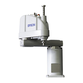
The system consists of a six-axis robot arm, teach pendant, gripper or other
tool, a controller running ash, as well as an umbilical cable. The cable
conducts communications between the robot and controller as well as power
for the electronics embedded in the robot.
An F3 system: computer, teach pendant, controller, and arm.
The F3 robot is run by a program that can be developed either on the
controller with a terminal or teach pendant, or off-line on a computer using
Robcomm 3 or equivalent tools. From the teach pendant or a terminal you
can move the arm and teach locations. The robot can also be operated with
limitations using the front panel of the controller.

6 F3 Robot Arm User Guide
99-05-31
Component Parts
Before installing the robot system, locate and check that you have received
all the components.
•If you did not order options, the robot system is packaged in two
containers.
•Options may be shipped in separate containers and may include: gripper,
teach pendant, user guides, diskette(s), cable extensions, spares, etc.
•Use the following table to check off the components, which have been
ordered and received.
Component Check if
ordered Delivery
date Serial
number
•F3 arm
•hex key
•C500C controller
•umbilical cable
•fuse kit with AC power cable
•teach pendant override plug
•SYSIO override plug
•CROS diskettes (2)
•calibration diskette
•F3 User Guide
•Application Development Guide
•RAPL-3 Language Reference
Guide
Option Check if
ordered Delivery
date Serial
number
•Robcomm 3 diskettes
•teach pendant
•servo gripper
•end-of-arm i/o kit
Table of contents
Other CRS Robotics manuals
