CRT S 8040 User manual

Copyright CRT FRANCE 2016


CONTBNTS
WARNING ........................................................................................ 3
RBSBT ............................................................................................ 3
INSTALLATION .............................................................................. 4
Where And How To Mount Your Mobile CB Radio............................................................ 4
Antenna Installation ........................................................................................................ 5
Power Connection ............................................................................................................ 6
Basic Operations .............................................................................................................. 6
Adjustment Of SWR (Standing Wave Ratio) .................................................................... 7
HOW TO USB YOUR CB RADIO .................................................... 8
ront panel ...................................................................................................................... 8
Rear panel ...................................................................................................................... . 0
Norm Selection . .
Reset .............................................................................................................................. . .
TBCHNICAL CHARACTBRISTICS .............................................. 12
2
2

WARNING
Please install the antenna (connect to the location (B) in the back panel of the radio) and
set the SWR (Standing Wave Ratio) before transmitting. Otherwise it may result in des truc -
tion of the power amplifier, which is not covered by the guarantee.
Welcome to use
CRTS8040 is a Multi-norms and multi-function CB radio which provides you with top
performance.
With the use of SMT technology to guarantee the best stability, reliability and unprece d -
ented quality, is a new communication and is surely the
bes t choice for professional users of CB radios. Moreover, it adopts flash CPU in the radio,
which
makes ready for future upgrading and functions expand
ing. To ensure
that you use the radio to the fullest, please read this manual carefully before installing.
RBSBT
Hold key (7) [CH9/. 9] to power on the radio, it will reset and all channel data will resume
factory default setting.
CRTS8040
CRTS8040
step in personal
3

INSTALLATION
Where An How To Mount Your Mobile CB Ra io
A) You should choose the most appropriate setting from a simple and practical point of
view.
B) Your CB radio should not interfere with the driver or the passengers.
C) Remember to provide different wires for the passing and protection (e.g.: power,
antenna, accessory cabling) so that they do not in any way interfere with the driving of
vehicles.
A) To install your equipment, use the cradle (H) and the self-tapping screws (E) provided
(drilling diameter 4 mm). Take care not to damage the vehicle’s electrical system while
drilling the dash board.
E) Do not forget to insert the rubber joints (G) between the CB and its support as these
have a shock-absorbing effect which permits gentle orientation and tightening of the
set.
F) Choose where to place the microphone support and remember that the microphone
cord must stretch to the driver without interfering with the controls of the vehicle.
G) As the transceiver has a frontal microphone socket, it can be set into the dash board.
You will need to add external loud speaker to improve the sound quality of communi -
cations(connector ext. SP situated on the back panel (D).
Ask your dealer for advice on mounting your CB radio.
G
E
H
F
D
B
C
E
E
H
F
G
E
4

Antenna Installation
a) Choosing antenna:
– or CB radios, the longer the antenna, the better its results. Your dealer will help you
with your choice of antenna.
b) Mobile antenna:
– Must be fixed to the vehicle where there is a maximum of metallic surface (ground
plane), away from windscreen mountings.
– If you already have a radio-telephone antenna installed, the CB antenna should be
higher than this.
– There are two types of antenna: Pre-regulated antenna which should be used on a good
ground plane (e.g. car roof or lid of the boot), and adjustable antenna which offer a much
larger frequency range and can be used on a smaller ground plane.
– or an antenna which must be fixed by drilling, you will need a good contact between
the antenna and the ground plane. To obtain this, you should lightly scratch the surface
where the screw and tightening star are to be placed.
– Be careful not to pinch or flatten the coaxial cable (as this runs the risk of break down
and/or short circuiting).
– Connect the antenna to location (B).
c) Fixed antenna:
A fixed antenna should be installed in a space as spacious as possible. If it is necessary
for you to fix the antenna to a mast, you need to keep it as per the requirements of the
laws in force (please turn to professional advice).
Output Radius Patterns
5

Power Connection
This is protected against an inversion of polarities. However, before switching it on, you
are advised to check all the connections. Your equipment must be supplied with a con ti -
nued current of . 2 volts (A). Today, most cars and lorries are negative earth. You can
check this by making sure that the negative terminal of the battery is connected either to
the engine block or to the chassis. If this is not the case, you should consult your dealer.
WARNING: Lorries generally have two batteries to supply a voltage of 24 volts, in which
case it will be necessary to insert a 24/. 2 volt converter into the electrical circuit. The
following connection steps should be carried out with the power cable disconnected
from the set
a) Check whether the battery is of . 2 volts.
b) Locate the positive and negative terminals of the battery (+ is red and – is black).
Should it be necessary to lengthen the power cable, please use the same or a superior
type of cable.
c) It is necessary to connect your CB to a permanent (+) and (–). We advise you to connect
the power cable directly to the battery (as the connection of the CB cable to the wiring
of the car-radio or other parts of the electrical circuit may, in some cases, increase the
possibilities of interference).
d) Connect the red wire (+) to the positive terminal of the battery and the black (–) wire to
the negative terminal of the battery.
e) Connect the power cable to your CB radio.
WARNING: Never replace the original fuse (5A) by one of a different value.
Basic Operations
a) Connect the microphone.
b) Check the antenna connections.
c) Turn the set on by turning the volume knob clockwise.
d) Turn the squelch knob to minimum ( ull-anti clockwise).
e) Adjust the volume to a comfortable level.
f) Go to channel 20@EC by using either the [∫] or [√] key.
Towards
starter
Connected
to chassis
6

A justment Of SWR (Stan ing Wave Ratio)
WARNING: This must be carried out when you use your CB radio for the first time (and
whenever you re-position your antenna). The adjustment must be carried out in an
obstacle-free area
Adjustment should be operated with external SWR meter.
a) To connect the SWR meter
Connect the SWR meter between the CB radio and the antenna as close as possible to
the CB radio (use a maximum of 40cm cable)
b) To adjust the SWR meter
- Set the CB to channel 20@EC band in M
- Put the switch on the SWR meter to position CAL or WD
- Press the <<Push-To-Talk>> switch on the microphone to transmit.
- Bring the index needle to by using the calibration key.
- Change the switch to position SWR (reading of the SWR level)
The reading on the meter should be as near as possible to . . If this is not the case,
re-adjust your antenna to obtain a reading as close as possible to . .
(An SWR reading between . and . .8 is acceptable).
▼
7

HOW TO USB YOUR CB RADIO
Front panel
. ) OFF/VOLUME
a) To turn the set on, turn the knob (. ) clockwise.
b) To increase the sound level, turn the same knob further clockwise.
2) SQUELCH
Manual Squelch: Turn the Squelch knob (2) clockwise to the exact point where all back-
ground noise disappears. Please note that this control is fine regulation, if you set this
Squelch control to the maximum (fully clockwise), the radio can only receive the strongest
signal.
3) Microphone Jack
Connect a six pin microphone supplied with radio.
4) LCA
Display for channel, RX/RX status, mode, H/L power, etc.
5) BP (on the Microphone)
If press the call key (5) [BP] while holding the transmit key (. . )
[PTT], a calling tone will be transmitted and can be heard by
other participants, provided their radio is set to the same
channel and the same modulation type.
DNBPUP
5
11
8

6) AM/FM
Modulation Mode selection: This key (6) [AM/ M] allows selecting the AM or M modula-
tion. Your modulation mode has to correspond to the one of your correspondent.
With the version ull Multi Norm in the norm UK, your can switch between the EU band
and the UK band, which is indicated by symbol "EU" or "UK", by pressing the key (6)
[AM/ M ]. The CB band EU consists of the 40 CEPT channels.
The CB band UK consists of 40 channels starting from 27.60. 25 MHz to 27.99. 25 MHz.
7) CH9/19
It contains the priority channels 9 and . 9, press the key (7) [CH9/. 9] once to select priority
channel 9, press the key (7) [CH9/. 9] again to set priority channel . 9.
8) [√] key (DN key on the microphone)
Channel down; selected channel downward.
9) [∫] key (UP key on the microphone)
Channel up; selected channel upward.
All channels can be selected by channel selector keys (8) or (9). The selected channel is
displayed on the LCD. In communication both transceivers (the receiving and transmitting
party) need to be in the same channel and under same modulation type.
. 0) SCAN
Press the key (. 0) [SCAN] to enable the SCAN function. Before enabling the SCAN
function, firstly turn the SQ control clockwise till the background noise is cut out.
Then press the key (. 0) [SCAN], radio will automatically scan all channels and the SC icon
will appear on the LCD.
When a signal is detected on a channel, scanning stops on this channel. You can receive
the calling, and also, can transmit on this channel by pressing PTT key. If there is no trans-
mission or detected signal on that channel within 5 seconds, radio will start scanning
again. To exit the SCAN function, press the SC key or the PTT key.
. . ) PTT (on the microphone)
To transmit, press and hold the key (. . ) [PTT] and the TX icon will appears on the LCD.
or best quality, please speak normally at a distance of 2 - 4 inches.
Speaking too loudly will cause distortions and make the signal difficult to understand.
On completion of the transmission release the PTT key and the radio will revert to
receiving mode.
9
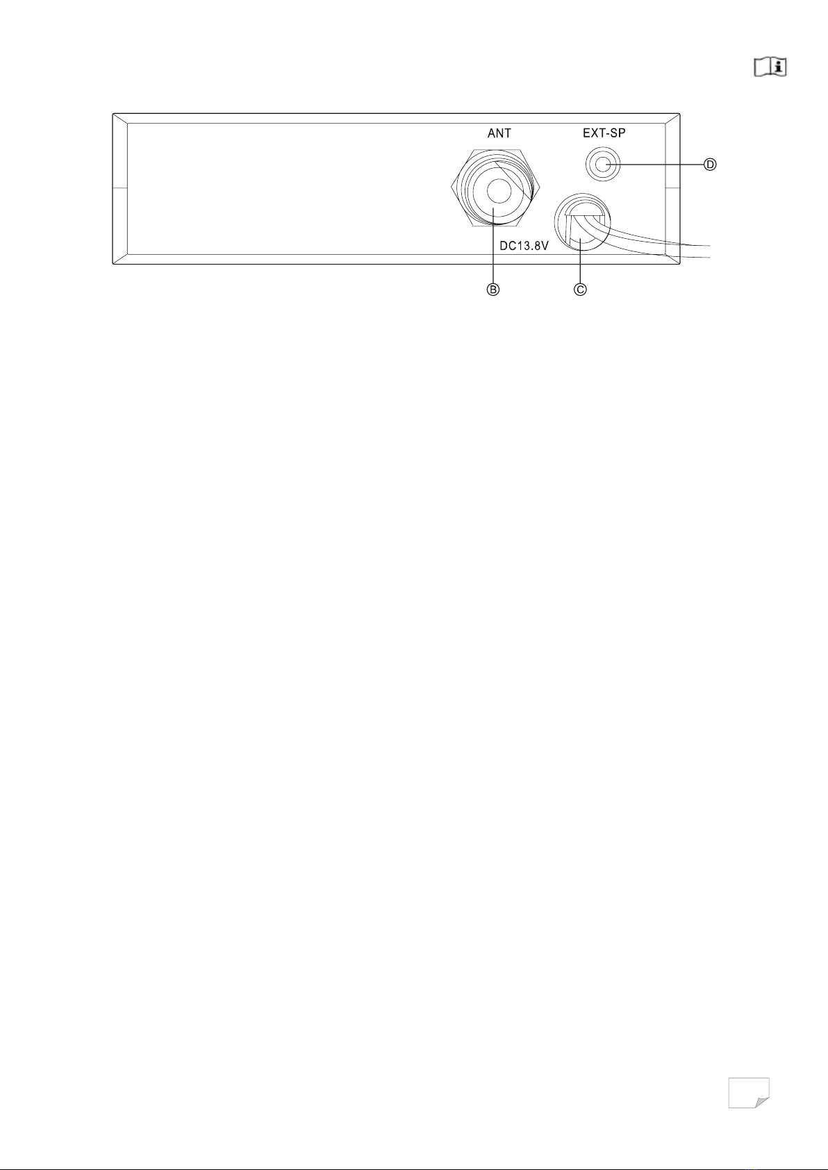
Rear panel
B) ANT
Plug (PL-259) for connecting the antenna with an 50 Ohms coaxial cable.
C) AC13.8V
. 3.8 V DC power cord with 5 A fuse.
D) E T-SP
The radio is equipped with a 3.5 mm jack socket (D) at the rear panel to connect an
external speaker of 4 - 8 ohm impedance.
At 4 ohms the speaker load can be 4 watts. When the external speaker is connected,
the internal speaker will be switched off.
-
10
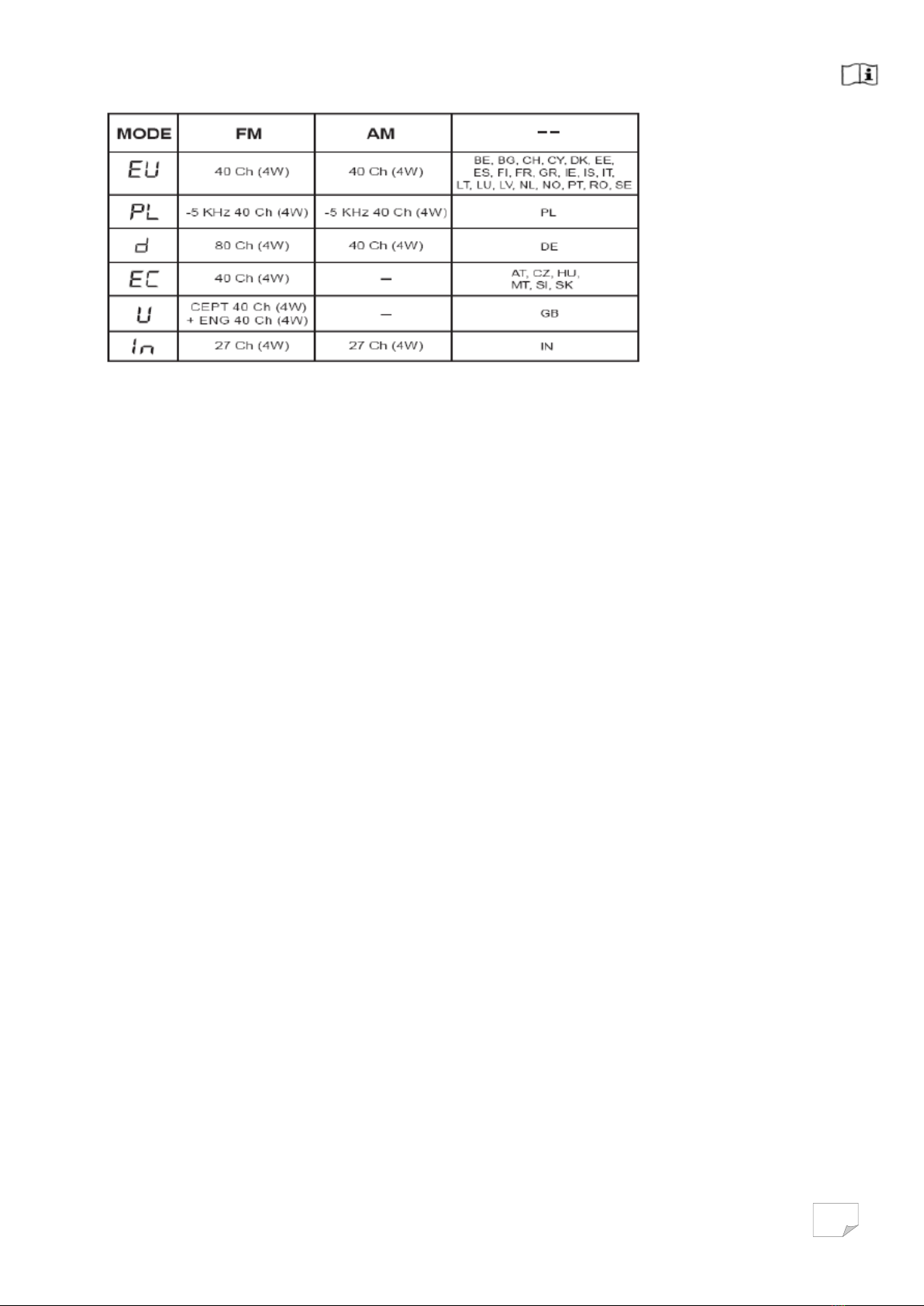
Norm Selection
The version ull Multi Norm can be set by the user to the following norms:
To change current norm, please hold the key (6) [AM/ M] while turning the radio on.
In the display, the symbol of the current norm appears, please select the norm by pressing
the channel selector key (8) or (9). To verify your selection, turn the radio off and on again,
the radio automatically returns to the selected operation mode.
NOTE: The norm is internally set to 40 channels M, 4 watts only.
Reset
Hold key (7) [CH9/. 9] to power on the radio, it will reset and all channel data will resume
factory default setting.
11

TBCHNICAL CHARACTBRISTICS
GBNBRAL
requency ranges 26.565 to 27.405MHz
Modulation modes AM/ M
Antenna impedance 50 Ohms
Power supply . 3.2V
Dimensions (in mm) . 50×. 40×4.
Weight 76. g
TRANSMISSION
Carrier power 4W
requency error ± 300Hz
Emitted power in the adj. channel inferior to 20µW
Transmission interference inferior to 4nW (–54dBm)
Audio response 300Hz to 3kHz in AM/ M
Microphone sensitivity 3mV
Maximum current max 3A
Modulated singal distortion inferior to 5%
RBCBPTION
Max sensitivity at 20dB sinad 0.8µV to . . 3 dB M; . .5µV to . 03 dBm AM
requency response 300Hz to 3kHz in AM/ M
Adjacent channel selectivity 60dB
Maximum audio power 3W
Squelch sensitivity Minimum 0.2µV, –. 20 dBm; Maximum . mV, –47 dBm
Maximum current 0.3A nominal/. .2A maximum
12

CONDITIONS OF GUARANTEE
Our transceivers CRT SUPERSTAR are guaranteed on 2 year. The other
equipments: 6 months.
Any abnormality of functioning must be indicated to your retailer, who will
intervene or will send it to our technical service for
control.
The spare parts of our devices are the object of no sending under guarantee.
Are excluded of the guarantee:
- The damages caused by accidents, shocks, natural elements (lightning,
thunderstorm, static electricity etc.)
- The transistors of power, the microphones, the fuses, the bad uses: badly
adjusted antenna (tos excessive), inversion of polarity, surge, bad connection etc.
recognized by our technical service.
- The interventions having modied the standards of approval of the device.
PROCEDURE ON RETURNING TO
THE AFTER-SALES SERVICE CRT
- If you send back a radio under guarantee for repair: You must pay the freight
costs to go. CRT will pay the freight costs return.
If the radio is not under guarantee postal charges are at your expense.
- Each device must be sent accompanied with a photocopy of the invoice as well
as with a descriptive note of the noticed defect.
If our AFTER-SALES SERVICE estimates the repair more expensive than the
value of the device, this one will send you an estimate which must have returned
to him accepted or refused. If the estimate is refused, the device will have carriage
forward return.
2

DECLARATION OF CONFORMITY
We hereby declare under our responsability that the product :
BRAND : CRT
Model : S 8040
Description : Mobile transceiver
Satisfies all the technical regulations applicable to the product within the scope of
directive R .TTE 1999/5/CE european standarts
EN 60950-1 +A11
EN 301 489-1
EN 301 489-13
EN 300 433-1
EN 300 433-2
EN 300 135-1
EN 300 135-2
Update : EMF : EN 62311
The object of the declaration described above is in conformity with the relevant Union harmonization
legislation: Directive 2004/108 / EC (until April 2016) Directive and 2014/30 / EU (from 20 April 2016)
Notified Body : EMCC DR Rasek Gmbh Germany
C.R.T. FRANCE INTERNATIONAL S.A.R.L.
Route de Pagny - 21250 SEURRE - FRANCE
Capital de 762 500 euros
Tél. 03 80 26 91 91 - Fax : 03 80 26 91 00
E-mail : superstar@crtfrance.com
Web site : www.crtfrance.com
Mr CELESTRANO PHILIPPE
GERANT
Le 04/11/2016
Table of contents
Other CRT Radio manuals


