CrustBuster 5020 User manual

P.O. Box 526 - Spearville, Kansas 67876 - (620) 227-7106
crustbuster.com
5020
Min-Till Drill
Owner's Manual
(07-98) # 605972

Identification
Your CrustBuster® drill is identified by a Serial Number and Model Number. Record these numbers
in the spaces provided in this manual and refer to them when ordering parts or requesting service.
Serial Number Model Number
Warranty
WARRANTY: In addition to the implied warranties of fitness and of merchantability,
CrustBuster®/Speed King, Inc. warrants new products sold by it to be free from defects in
workmanship and material for a period of 12 months, from the date of delivery to the first user
customer. Warranty on purchased parts (cylinder, blades, bearings, shanks, etc.) will be the
same as that offered by the appropriate manufacturer of these parts.
EXCLUSIONS: No warranty of any kind is made by CrustBuster®/Speed King, Inc. with
regard to new products which have been subject to operation in excess of recommended
capacities, misuse, abuse, negligence, or accident, or have been altered or repaired in any
manner not authorized by CrustBuster®/Speed King, Inc. CrustBuster®/Speed King, Inc. is
constantly striving to improve its products. Changes in design and improvement will be made
whenever CrustBuster®/Speed King, Inc. believes the efficiency of its products will be
improved thereby, but without incurring any obligation to incorporate such improvements in
any products which have been shipped or are in service. No obligation exists for
compensation of unauthorized repairs or modifications without prior approval. And in no event
will CrustBuster®/Speed King, Inc. be liable for consequential damages, such as but not
limited to: downtime, delayed or late tillage or planting, etc.
WARRANTY REGISTRATION: This warranty is not valid unless registered with
CrustBuster®/Speed King, Inc. within 10 days from the date of purchase. It is the sole
responsibility of the selling retail dealer to fill out the registration forms and see that they are
properly filed with CrustBuster®/Speed King, Inc. This can be done at crustbuster.com.
WARRANTY PROCEDURE: Should any part fail to conform with this warranty,
CrustBuster®/Speed King, Inc. will repair or replace the part or parts which do not conform.
If a part is defective, take it to your authorized CrustBuster® Farm Equipment Dealer
immediately, along with your warranty registration, and complete the proper forms requesting
a warranty adjustment. Our representative will pick up the part to be returned to the factory
for examination. If the customer (first user) requests that a new part be substituted for the old
part, a new part will be charged to the dealer who will in turn charge the customer. If the part
is found by us to be defective, a credit for the part will be given to the dealer to be passed on
to the customer. If the dealer or customer wishes to repair the part, this will be done only if
authorized by CrustBuster®/Speed King, Inc. This warranty procedure is in addition to all
remedies authorized by law.
CRUSTBUSTER®/SPEED KING, INC.
Box 1438
Dodge City, KS 67801
Specifications are subject to change without notice. ® is a registered trademark of CrustBuster/Speed King, Inc.

Table of Contents
Identification & Warranty . . . . . . . . . . . . . . . . . . . . . . Inside Cover
Safety........................................... 2-6
OperatingCautions................................... 7
Field Operating Checklist . . . . . . . . . . . . . . . . . . . . . . . . . . . . . . 7
Setting Down Pressure & Seed Depth . . . . . . . . . . . . . . . . . . . . 8
WobbleSlotSeedCup ................................ 9
Chain Tension on Drive Shaft . . . . . . . . . . . . . . . . . . . . . . . . . . . 9
Calibration & Seed Rates . . . . . . . . . . . . . . . . . . . . . . . . . . . . . 10
Sprocket Box Operation . . . . . . . . . . . . . . . . . . . . . . . . . . . . . . 10
Meter Man Acreage Counter . . . . . . . . . . . . . . . . . . . . . . . . . . . 11
Lubrication, Maintenance, and Service . . . . . . . . . . . . . . . . . . . 11
SprocketLocations.................................. 12
OpenerSettings .................................... 13
RowSet-ups.................................... 14-16
SeedRateCharts................................ 17-24
Repair Parts:
Frame............................................ 26
WheelArm ........................................ 27
GrainBox ...................................... 28-29
Drive.......................................... 30-31
Gear Assembly - Left. . . . . . . . . . . . . . . . . . . . . . . . . . . . . . 32-33
Gear Assembly - Right . . . . . . . . . . . . . . . . . . . . . . . . . . . . 34-35
Min-TillOpener.................................. 36-37
Min-Till Opener Blades . . . . . . . . . . . . . . . . . . . . . . . . . . . . . . . 38
FeedTubes........................................ 39
CoverShield....................................... 39
Presswheel Assemblies. . . . . . . . . . . . . . . . . . . . . . . . . . . . . . . 40
LightingSystem..................................... 41

BE A SAFE OPERATOR
BY THINKING BEFORE ACTING
AND
BY READING
YOUR OWNER'S MANUAL
Avoid Accidents
Most accidents, whether they occur in
industry, on the farm, at home, or on the
highway, are caused by the failure of some
individual to follow simple and fundamental
safety rules or precautions. For this reason
most accidents can be prevented by recog-
nizing the real cause and doing something
about it before the accident occurs.
———————
Regardless of the care used in the design
and construction of any type of equipment,
there are many conditions that cannot be
completely safeguarded against without
interfering with reasonable accessibility and
efficient operation.
A CAREFUL OPERATOR
is the Best Insurance Against an Accident.
The complete observance of one simple
rule would prevent many thousands
of serious injuries each year.
That rule is:
Never Attempt to
Clean, Oil, or Adjust
A Machine While It Is In Motion.
To Our Customers
The following pages and illustrations are
printed to help supply you with the knowledge
to better operate and service your new
CrustBuster equipment.
We are proud to have you as a customer
and feel you will be proud to be a
CrustBuster owner.
Any piece of equipment needs, and must
have, a certain amount of service and main-
tenance to keep it in top running condition.
We have attempted to cover all the adjust-
ments required to fit most conditions; how-
ever, there may be times when special care
must be taken to fit a condition.
Study this owner's manual carefully and
become acquainted with all the adjustments
and operating procedures before attempting
to operate your new equipment. Remember,
it is a machine and has been designed and
tested to do an efficient job in most operating
conditions and will perform in relation to the
services it receives.
If special attention is required for some
condition, ask your CrustBuster dealer; he
will be glad to help and answer any questions
on operations and service of your new ma-
chine.
TAKE TIME FOR SAFETY
2

Safety
RECOGNIZE SAFETY INFORMATION
UNDERSTAND SIGNAL WORDS
FOLLOW SAFETY INSTRUCTIONS
3
Safety
OPERATE SAFELY
AVOID TIP-OVERS
KEEP RIDERS OFF MACHINE
4

Safety
HANDLE FUEL SAFELY - AVOID FIRES
PREPARE FOR EMERGENCIES
PRACTICE SAFE MAINTENANCE
5
Safety
WEAR PROTECTIVE CLOTHING
USE SAFETY LIGHTS AND DEVICES
TRANSPORT SAFELY
ALWAYS RAISE THE JACK STANDS BEFORE TRANSPORTING.
SHIFT THE TRACTOR INTO A LOWER GEAR WHEN TRANSPORTING DOWN STEEP
SLOPES OR HILLS.
DO NOT TRANSPORT UNLESS THE GRAIN DRILL REFLECTORS, LIGHTS, AND SMV
EMBLEM ARE EASILY VISIBLE FROM THE REAR.
NEVER TRANSPORT THE GRAIN DRILL FASTER THAN 32 KM/H (20 MPH.) REDUCE
SPEED WHEN TRAVELING OVER ROUGH GROUND OR WITH THE BOX FULL.
(CRUSTBUSTER DOES NOT RECOMMEND TRANSPORTING WITH A FULL GRAIN BOX.)
6

Before Operating This Equipment
Read and undertand this owner's manual.
Safety & Set-Up Instructions
FNEVER ALLOW ANYONE TO RIDE THE DRILL!
FCheck lug nuts or bolts. Torque to 100 ft. lbs. after approximately one mile and
periodically after.
FIf your tractor does not already have a lighting receptacle, install one. Always plug
in the drill lighting system to a correctly wired tractor and USE for transport safety.
Field Operating Checklist
____ Inflate tires to recommended air pressure. ( 44 psi)
____ Lubrication as required.
____ Seed shafts turned manually to check for obstructions and improper chain alignment on
drive sprockets.
____ Correct sprocket selection and slot width for seed type and size.
____ Calibration as required for accuracy.
____ Three point center link is adjusted for level drill operation.
____ Drill is hooked secure to tractor.
____ Down pressure set for soil conditions.
____ Acre meter reset.
____ Lower drill while moving forward to avoid plugging openers.
____ Check seed depth and adjust accordingly.
____ Allow no riders.
____ Rotate support stands UP before transporting or operating drill.
____ If transporting drill while box is full, turn drive wheels manually before drilling to assure
packing has not stopped seed flow. (CrustBuster does not recommend transporting with
full grain box.
7
Min-Till Drill
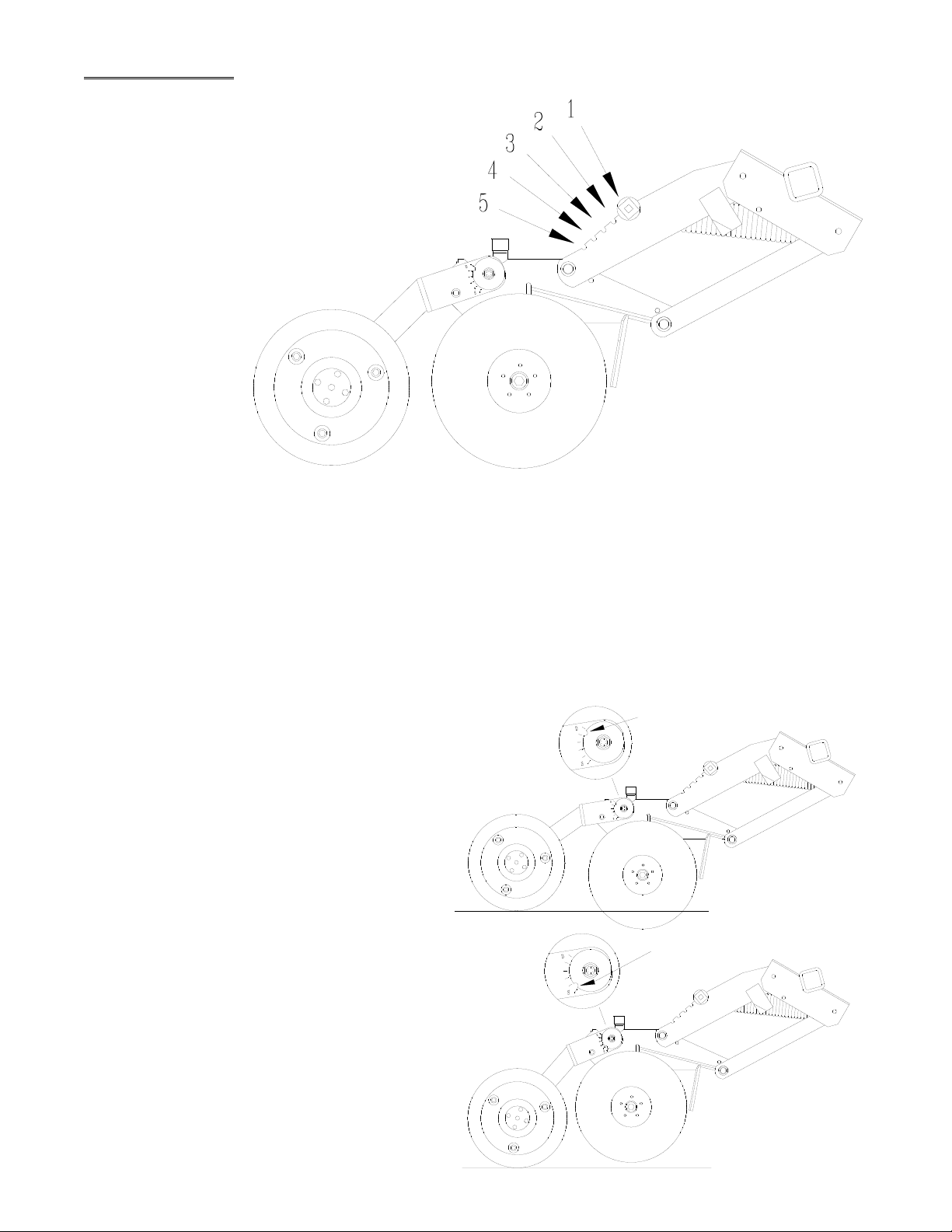
Setting Down Pressure
Opener pressure setting is easy and allows
separate settings for tire compaction areas to
different soil conditions from field to field. Ratchet
mechanism allows you to turn the pressure up or
down. The locking key rolls up or down the notch
gauge and locks to your desired setting from
140# to 250# per opener.
Notch 1 . . 140#
Notch 2 . . . 190#
Notch 3 . . 210#
Notch 4 . . 230#
Notch 5 . . 250#
Down Pressure Spring Adjustment
Row units that run in wheel tracks can be set
with heavier down pressure to assure solid
presswheel action. The following will help in
changing spring pressure.
1. Rotate the tool bar to raise the opener. Fold
up the walkboard to give good access to
the front of the opener.
2. Using ratchet type wrench, roll locking key
up or down notch gauge to desired setting.
Setting Seed Depth
Understanding the tool bar operation and
parallel linkage design will make setting the drill
much easier. Refer to the drawing on the next
page.
Rotating the rockershaft DOWN
sets seed depth more SHALLOW.
Each tool bar is controlled by a hydraulic cylin-
der within each wheel arm. An adjustable depth
stop sets the travel of the cylinder which in turn
determines how much the tool bar rotates.
Set depth stop in middle position as a starting
point. To set deeper seed depth, screw the
depth stop out and lengthen the cylinder travel.
The opener and presswheel relationship con-
trols the depth of seed.
When lowering the openers, be sure the tool
bar is in the full down position and the
cylinder is retracted against the depth stop.
The parallel linkage must be "set" to
achieve the desired down pressure and
depth control.
Individual presswheels may be set to correct for
wheel track compaction. Usually, these will only
need to be adjusted once if the same tractor is
pulling the drill the entire season. At the rear of
the opener, a cam rotation bracket holds the
single presswheel arm. Turn the cam toward
the "D" or "S" to achieve the desired depth
control.
LOWERING the presswheel
will set seed depth more SHALLOW.
DEEP
SHALLOW
8

Wobble Slot Seed Cup Adjustments and Service
The wobble slot seed cups should be checked
against the slot gauge initially and anytime service
has been performed on the seed shaft or individual
seed cups. Refer to the drawing below for proper
adjustment if repairs have been made.
To verify that all seed cups are set the same on
the shaft, start with all cups fully closed. A slight
crack between the cup halves would be considered
normal tolerance. If any individual cup is not
"zeroed out," open the slot width using the adjust-
ing handle, loosen allen set screws and adjust to
equal others on shaft.
To determine if the gauge is reflecting the correct
seed cup slot width, open the seed cups using the
adjusting handle. Notice that wobble slot halves
are positioned differently on the hex shaft. Identify
a cup that will accept a piece of ½" keystock or
other measuring device comfortably and give solid
contact against each half. It may be necessary to
turn the hex shaft slightly to position the particular
seed cup correctly. Close the slot width firmly
against the measuring device. At the cup next to
the wobble slot adjusting handle, position
the gauge to equal the slot width you have just
measured with the keystock by loosening with a
screwdriver and sliding in or out.
Before removing the keystock, make certain the
bearing located on the adjustment lever is securely
running between the shaft bushings. Adjusting
bushings must be set screwed tightly to shaft with
zero to 1/64" tolerance between the bushing and
bearing. Excess tolerance in this area will allow
the seed shaft to float from right to left, thus open-
ing and closing wobble slot and varying the seed
rate.
Small changes in rate can be made by opening or
closing slot width. To close the slot width with
grain in the box, close the slot down a maximum of
1/8" and then rotate the shaft one turn to clear the
slot. Repeat this process until the desired slot
width is selected.
Seeding rate is affected by seed size, seed
treatments, foreign material, and test weight.
Refer to seed rate charts as guidelines for
desired seeding rates.
Chain Tension on Drive Shaft
When making sprocket changes to the seed
shaft, tighten chain to leave approximately 1/2"
of flex. The final sprocket must allow the hex
shaft to slide within the sprocket when the
adjusting lever is moved. If the chain is too
tight, bowing and binding of box end will occur
making seed cup adjustment difficult. Lightly
lubricate the shaft where the sprocket will slide.
DO NOT OVERTIGHTEN CHAIN.
9

Calibration, Seed Rates and Sprocket Box
Calibration/Drilling Rates
Planting the right rate can be frustrating. Some-
times the end result is not what the rate chart
indicates. Seeding rate is affected by seed size,
seed treatments, foreign material, test weight,
and tire air pressure.
1. Always plant clean seed.
2. Check tire air pressure.
3. Seed treatments vary by type and time of
application.
Some seeds are treated at the processor. Drill
box treatments are common methods of applica-
tion. Each of these can "gum" up the wobble slot
cup halves and reduce final seeding rate.
Treated seed often flows differently than non-
treated seed.
A general method for checking quantities drilled
is as follows:
1. Set drill for desired seeding rate.
2. Fill the box level; then pull drill for a short
distance to settle seed. Refill box exactly
level full.
3. Drill a calculated one acre.
4. Carefully weigh the seed required to refill the
box level full.
5. Compare the amount used versus that stated
on the rate chart.
6. Adjust seeding rate by changing the sprocket
combination or wobble slot width.
One method involves catching seed from one or
more seed cups and utilizing a density scale to
determine actual rates. These scales are com-
mercially available, inexpensive and very easy to
use. Information can be obtained from
CrustBuster®/Speed King, Inc.
Sprocket Box Operation
The sprocket box design will enable the operator
to set a wobble slot width once for a given seed
size and change rates by changing the speed of
the seed shaft. Choose a range of seeding rates
that you wish to operate in, set the slot width as
indicated by the chart and simply change knob
position with the slide handle to effect seed rate.
A narrow slot width will produce more even
distribution and spacing in the row.
When changing derailleur, be sure openers
are rotated out of ground.
To change position, move throw-out lever toward
the rear to disengage the chain from the lower
sprocket. Pull the spring loaded collar outward
with two fingers and slide side to side to the
desired gear position. Pull throw-out lever for-
ward to re-engage the chain.
Sprocket Box
10
Spacing 20'
6" .00265
7 ½" .00212
8" .00191
10" .00152
Do Not Attempt To Service
Your Drill While
It Is In Motion!
Meter Man Acreage Counter
(Option)
Calibration
Use the formulas below to determine your imple-
ment calibration factor or refer to the predeter-
mined factors listed when using CrustBuster
drills.
DT = Distance traveled with one counter shaft rotation
(when using two magnets, divide DT by 2).
WW = Working Width of implement (in inches).
WW x DT/2 = Calibration factor
6272640
NOTE: Whenever a gear change is made on the
shaft being monitored, you will need to enter a
new calibration factor.
Entering Calibration Factor
1. Depress ON/C
2. Round off factor to 5 digits
3. Enter factor (remember decimal point)
4. Depress + key
5. Depress = key
6. Depress decimal point (screen display 0)
Meter Man Factors by Model
5020 Drills
Scraper Blade Replacement
Opener blade inside scrapers are spring loaded
and require no adjustment. To replace the
scraper blades, remove rear lock nut and slide
both blades from stem. Assemble with new
blades and replace onto stem being careful not to
overtighten lock nut.
NOTE: Do not over tighten lock nut. Be sure
scapers move freely. Failure to do so
will result in damage to scrapers and
proper operation of scrapers.
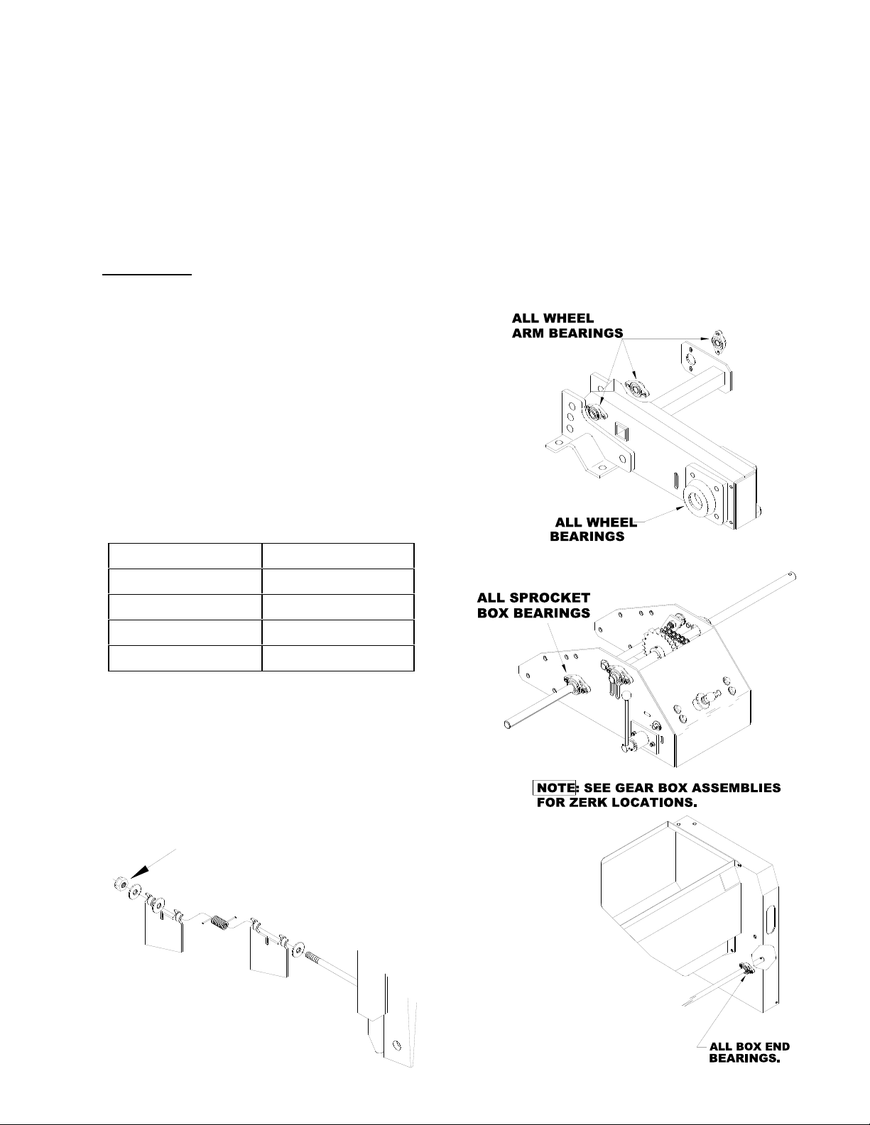
Lubrication, Maintenance,
and Service
Proper maintenance will extend the life of your
drill and give you years of excellent performance.
Refer to the repair part drawings and the illustra-
tions below for lubrication requirements. Use a
high quality grease in pivot points and bearings.
On greaseable sealed bearings, be careful not to
over-grease and destroy the dirt seal. Pay atten-
tion to recommended intervals. Oil chains with a
chain lube. A light penetrating oil or liquid graph-
ite should be used on seed cups initially and at
the end of each season. Clean cups with air
pressure or vacuum before applying penetrating
oil.
11
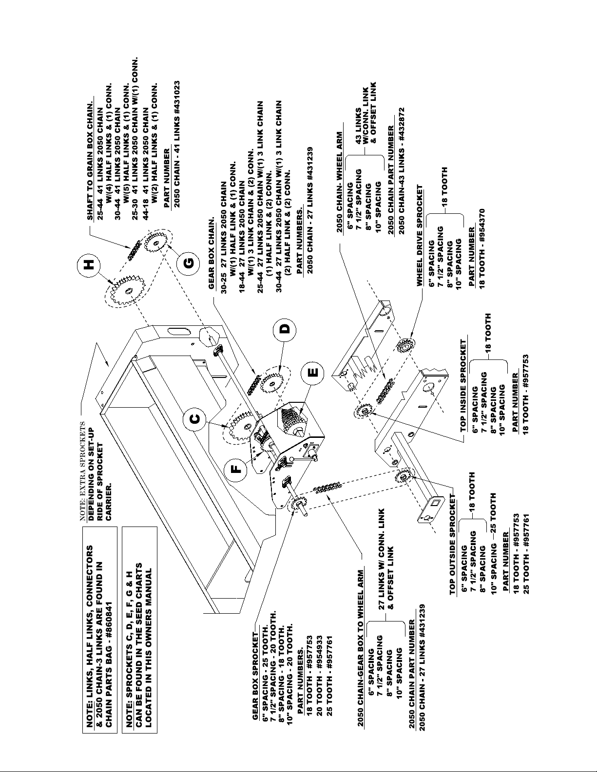
5020 Sprocket Locations
12
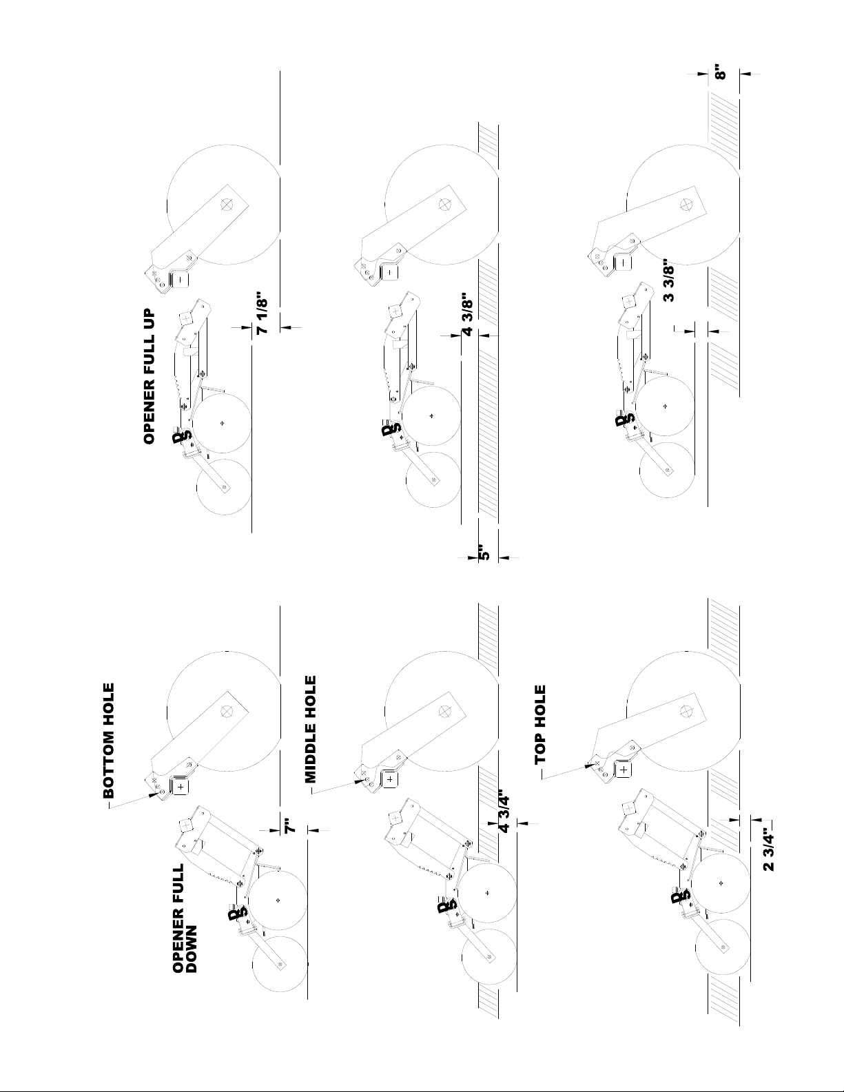
Conventional
Setting Low Ridge
Setting High Ridge
Setting
Opener Settings
13
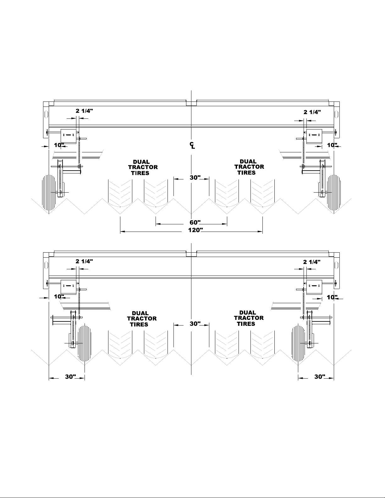
30" Row Set-ups
Top view is set-up for dual tires or single tires.
Bottom view can be set-up for single or dual tires. To get the 30 inch dimension to the
center of the wheel, the right wheel arm is mounted on the left, and the left wheel arm
is mounted on the right.
14
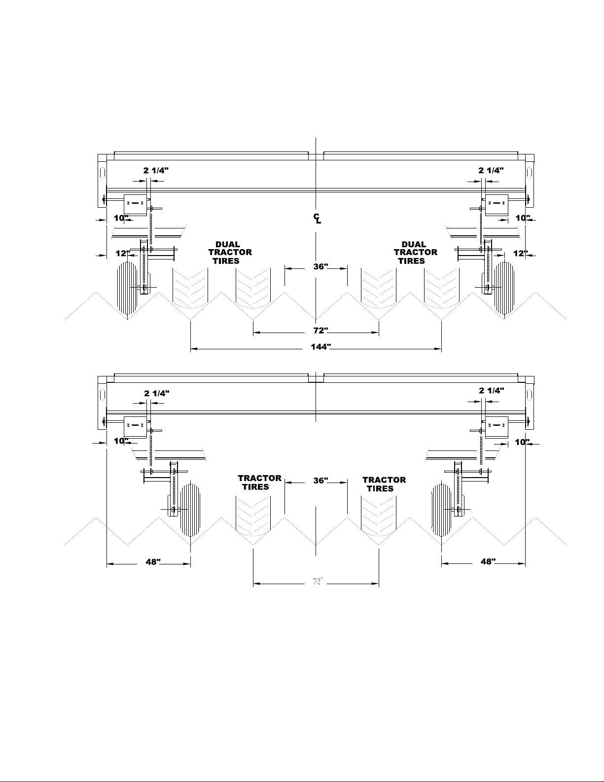
36" Row Set-ups
Top view is set-up for dual tires or single tires.
Bottom view can be set-up for single tires only by moving the right wheel arm to the left,
and the left wheel arm to the right.
15
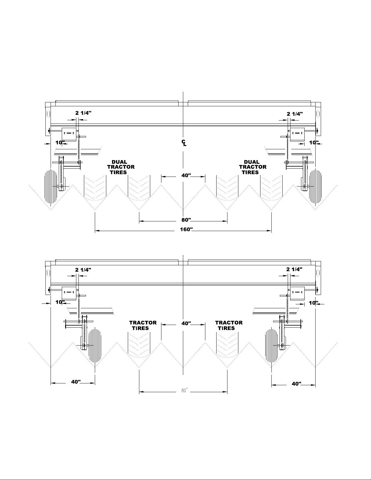
40" Row Set-ups
Top view is set-up for dual tires or single tires.
Bottom view can be set-up for single tires only by moving the right wheel arm to the left,
and the left wheel arm to the right.Row Set-ups
16

Seed Rate Charts
ALFALFA BARLEY
Sprockets Slot Width Sprockets Slot Width
Derailleur Box End Pounds/Acre Derailleur Box End Pounds/Acre
C D E F G H 1/8" 1/4" C D E F G H 1/2" 5/8" 3/4"
18 44 16 30 25 44 5 8 30 25 16 30 25 44 31 38 45
18 44 17 30 25 44 5 9 30 25 17 30 25 44 33 40 48
18 44 18 30 25 44 5 9 30 25 18 30 25 44 34 43 51
18 44 19 30 25 44 6 10 30 25 19 30 25 44 36 45 54
18 44 20 30 25 44 6 11 30 25 20 30 25 44 38 47 57
18 44 21 30 25 44 6 11 30 25 21 30 25 44 40 50 60
18 44 22 30 25 44 7 12 30 25 22 30 25 44 42 52 63
18 44 23 30 25 44 7 12 30 25 23 30 25 44 44 54 65
25 44 16 30 25 44 7 12 30 25 16 30 25 30 45 56 67
25 44 17 30 25 44 7 12 30 25 17 30 25 30 48 59 71
25 44 18 30 25 44 8 13 30 25 18 30 25 30 51 63 75
25 44 19 30 25 44 8 14 30 25 19 30 25 30 53 66 79
25 44 20 30 25 44 8 15 30 25 20 30 25 30 56 69 83
25 44 21 30 25 44 9 15 30 25 21 30 25 30 59 73 88
25 44 22 30 25 44 9 16 30 25 22 30 25 30 62 76 92
25 44 23 30 25 44 10 17 30 25 23 30 25 30 65 80 96
30 44 16 30 30 44 10 17 30 25 16 30 30 25 65 80 96
30 44 17 30 30 44 10 18 30 25 17 30 30 25 69 85 102
30 44 18 30 30 44 11 19 30 25 18 30 30 25 73 90 108
30 44 19 30 30 44 12 20 30 25 19 30 30 25 77 95 114
30 44 20 30 30 44 12 21 30 25 20 30 30 25 81 100 120
30 44 21 30 30 44 13 22 30 25 21 30 30 25 85 105 126
30 44 22 30 30 44 13 23 30 25 22 30 30 25 89 110 132
30 44 23 30 30 44 14 24 30 25 23 30 30 25 93 115 138
30 25 16 30 25 44 14 25 25 30 16 30 44 18 92 113 136
30 25 17 30 25 44 15 26 25 30 17 30 44 18 97 120 144
30 25 18 30 25 44 16 28 25 30 18 30 44 18 103 127 153
30 25 19 30 25 44 17 29 25 30 19 30 44 18 109 134 161
30 25 20 30 25 44 18 31 25 30 20 30 44 18 114 141 170
30 25 21 30 25 44 19 32 25 30 21 30 44 18 120 149 178
30 25 22 30 25 44 20 34 25 30 22 30 44 18 126 156 187
30 25 23 30 25 44 21 35 25 30 23 30 44 18 132 163 195
30 25 16 30 25 30 21 36
30 25 17 30 25 30 22 38
30 25 18 30 25 30 24 41
30 25 19 30 25 30 25 43
30 25 20 30 25 30 26 45
30 25 21 30 25 30 28 48
30 25 22 30 25 30 29 50
30 25 23 30 25 30 30 52
17

Seed Rate Charts
CANOLA CORN
Sprockets Slot Width Sprockets Slot Width
Derailleur Box End Pounds/Acre Derailleur Box End Pounds/Acre
C D E F G H 3/16" 1/4" 3/8" C D E F G H 1/2" 5/8" 3/4"
18 44 16 30 25 44 5 7 10 18 44 16 30 25 44 6 8 10
18 44 17 30 25 44 5 8 11 18 44 17 30 25 44 6 8 10
18 44 18 30 25 44 5 8 11 18 44 18 30 25 44 6 9 11
18 44 19 30 25 44 6 8 12 18 44 19 30 25 44 7 9 11
18 44 20 30 25 44 6 9 13 18 44 20 30 25 44 7 10 12
18 44 21 30 25 44 6 9 13 18 44 21 30 25 44 7 10 13
18 44 22 30 25 44 7 10 14 18 44 22 30 25 44 8 11 13
18 44 23 30 25 44 7 10 14 18 44 23 30 25 44 8 11 14
25 44 16 30 25 44 7 10 14 25 44 16 30 25 44 8 11 13
25 44 17 30 25 44 7 10 15 25 44 17 30 25 44 8 12 14
25 44 18 30 25 44 8 11 16 25 44 18 30 25 44 9 12 15
25 44 19 30 25 44 8 12 17 25 44 19 30 25 44 9 13 16
25 44 20 30 25 44 8 12 17 25 44 20 30 25 44 10 14 17
25 44 21 30 25 44 9 13 18 25 44 21 30 25 44 10 14 18
25 44 22 30 25 44 9 13 19 25 44 22 30 25 44 11 15 18
25 44 23 30 25 44 10 14 20 25 44 23 30 25 44 11 16 19
30 44 16 30 30 44 10 14 20 30 44 16 30 30 44 11 16 19
30 44 17 30 30 44 10 15 21 30 44 17 30 30 44 12 17 20
30 44 18 30 30 44 11 16 23 30 44 18 30 30 44 13 18 22
30 44 19 30 30 44 12 17 24 30 44 19 30 30 44 13 19 23
30 44 20 30 30 44 12 18 25 30 44 20 30 30 44 14 20 24
30 44 21 30 30 44 13 19 26 30 44 21 30 30 44 15 21 25
30 44 22 30 30 44 13 19 28 30 44 22 30 30 44 15 22 26
30 44 23 30 30 44 14 20 29 30 44 23 30 30 44 16 23 28
30 25 16 30 25 44 14 21 29 30 25 16 30 25 44 17 23 28
30 25 17 30 25 44 15 22 31 30 25 17 30 25 44 18 25 30
30 25 18 30 25 44 16 23 33 30 25 18 30 25 44 19 26 32
30 25 19 30 25 44 17 25 35 30 25 19 30 25 44 20 27 34
30 25 20 30 25 44 18 26 37 30 25 20 30 25 44 21 29 35
30 25 21 30 25 44 19 27 39 30 25 21 30 25 44 22 30 37
30 25 22 30 25 44 20 28 41 30 25 22 30 25 44 23 32 39
30 25 23 30 25 44 21 30 42 30 25 23 30 25 44 24 33 41
30 25 16 30 25 30 21 30 43 30 25 16 30 25 30 26 34 42
30 25 17 30 25 30 22 32 46 30 25 17 30 25 30 27 36 44
30 25 18 30 25 30 24 34 49 30 25 18 30 25 30 28 38 47
30 25 19 30 25 30 25 36 51 30 25 19 30 25 30 29 40 50
30 25 20 30 25 30 26 38 54 30 25 20 30 25 30 31 42 52
30 25 21 30 25 30 28 40 57 30 25 21 30 25 30 32 44 55
30 25 22 30 25 30 29 42 59 30 25 22 30 25 30 34 46 58
30 25 23 30 25 30 30 44 62 30 25 23 30 25 30 35 48 60
30 25 16 30 30 25 30 44 62 30 25 16 30 30 25 35 48 60
30 25 17 30 30 25 32 46 66 30 25 17 30 30 25 37 52 64
30 25 18 30 30 25 34 49 70 30 25 18 30 30 25 40 55 68
30 25 19 30 30 25 36 52 74 30 25 19 30 30 25 42 58 72
30 25 20 30 30 25 38 55 78 30 25 20 30 30 25 44 61 75
30 25 21 30 30 25 40 57 82 30 25 21 30 30 25 46 64 79
30 25 22 30 30 25 42 60 86 30 25 22 30 30 25 48 67 83
30 25 23 30 30 25 44 63 89 30 25 23 30 30 25 51 70 87
18
Table of contents
Other CrustBuster Drill manuals


