Cryo Bio System SYMS I User manual

This document may not be reproduced, copied, transmitted or given to a party other than the end-user without the explicit
written authorization of Cryo Bio System.
IFU-000100 [Indice C] [SYMS I] [P. 1/ 18]
User manual
SYMS I MANUAL SEALING MACHINE
For CBS™ High Security straws and HSV High Security Vitrification straws
Read this manual carefully before using the SYMS I manual sealing machine
CRYO BIO SYSTEM –www.cryobiosystem.com –tel +33 (0)2 33 34 64 64
Edition: 2021

This document may not be reproduced, copied, transmitted or given to a party other than the end-user without the explicit
written authorization of Cryo Bio System.
IFU-000100 [Indice C] [SYMS I] [P. 2/ 18]
Contents
1 INTRODUCTION ............................................................................................................................................. 3
1.1 Applications.................................................................................................................... 3
1.2 Mechanical characteristics.......................................................................................... 3
1.3 Electrical characteristics............................................................................................... 3
1.3.1 Equipment nominal value ...................................................................................... 3
1.3.2 Environmental parameters..................................................................................... 4
1.3.3 Electrical safety ....................................................................................................... 4
1.4 Precautions ..................................................................................................................... 4
2HYGIENE AND SAFETY .............................................................................................................................. 5
2.1 Scope of application ..................................................................................................... 5
2.2 Protection, Safety ........................................................................................................... 5
2.2.1 Safety indications .................................................................................................... 5
2.2.2 Installation safety rules ........................................................................................... 6
3SYMS I...................................................................................................................................................... 8
3.1 Overview ......................................................................................................................... 8
3.2 Description of devices................................................................................................... 8
3.2.1 SYMS I manual sealing machine........................................................................... 8
4ASSEMBLY AND ADAPTATION................................................................................................................ 11
5PROCEDURE ........................................................................................................................................... 15
5.1 Operation of the individual straw welder ................................................................. 15
6MAINTENANCE ...................................................................................................................................... 17
6.1 Precautions ................................................................................................................... 17
6.2 Maintenance ................................................................................................................ 17
6.3 Transport and storage.................................................................................................. 17
6.4 Recycling of worn parts............................................................................................... 17
6.5 Non-responsibility clause............................................................................................ 17
7CONTACT ............................................................................................................................................... 18

This document may not be reproduced, copied, transmitted or given to a party other than the end-user without the explicit
written authorization of Cryo Bio System.
IFU-000100 [Indice C] [SYMS I] [P. 3/ 18]
1 INTRODUCTION
1.1 Applications
The SYMS I sealer is a tabletop device designed to seal CBS™ High Security of a
capacity of 0.3 ml and 0.5 ml and High Security Vitrification straws for applications
such as:
Epidemiology research departments;
Biobanks;
Serum banks;
Cell and gene therapy units;
Vaccine producing, pharmaceutical companies (living cells);
Genetic heritage conservatories (animal, vegetable, microbiological);
Laboratories and medical officers specializing in reproduction biology;
Sperm banks.
1.2 Mechanical characteristics
Size (in mm)
Length 230 mm
Width 220 mm
Height 170 mm
Mass (in kg) 6 kg
1.3 Electrical characteristics
1.3.1 Equipment nominal value
Sealer model
UF 400000 (ref. 016399) removable sealing block
Electric power
Power supply voltage 230 VAC +/- 10%
Power supply frequency 50/60 Hz
Consumed power 120 W max
Control circuit 12 V direct current
Thermal energy
Nature electrical
Power 19 A at 4 VAC

This document may not be reproduced, copied, transmitted or given to a party other than the end-user without the explicit
written authorization of Cryo Bio System.
IFU-000100 [Indice C] [SYMS I] [P. 4/ 18]
Protection by fuses
2 fuses of 2 A.T / 250 VAC / glass tube
5x20 mm, according to CEI127-2
standards.
1.3.2 Environmental parameters
Indoor use
Operating temperature from 5 to 30°C
Maximum relative humidity 80%
Atmosphere
The equipment must not be used at an altitude higher than 2000 m or in an explosive
or corrosive environment.
1.3.3 Electrical safety
Safety standards
Product in class I, requires installation with suitably protected ground.
Pollution degree 2.
1.4 Precautions
We advise you to read this manual with care. It has been produced to help you
discover our SYMS I manual sealing machine and to help you make the most of it.
This document may not be reproduced, copied, transmitted or given to a party other than the end-user without the explicit
written authorization of Cryo Bio System.
IFU-000100 [Indice C] [SYMS I] [P. 5/ 18]
2 HYGIENE AND SAFETY
2.1 Scope of application
The SYMS I sealer 230 V –UF400000 –ref. 016399 allows the sealing of CBS™ High
Security straws and High Security vitrification straws used in laboratories.
2.2 Protection, Safety
2.2.1 Safety indications
DANGER!
These indications refer to hazards due to electric voltages
DANGER!
These indications refer to hazards due to risks of burns.
DANGER!
These indications refer to hazards concerning the user and
the machine.

This document may not be reproduced, copied, transmitted or given to a party other than the end-user without the explicit
written authorization of Cryo Bio System.
IFU-000100 [Indice C] [SYMS I] [P. 6/ 18]
2.2.2 Installation safety rules
Installation
- To be safe, this equipment must be connected to an installation that is in conformity
(in France NFC 15-100), equipped with a ground connection, suitably protected
against ground faults.
- Operation on alternating current. The voltage and frequency must comply with the
indications given on the nameplate.
- In the event of damage to the mains cable, turn of the welder power supply
immediately. "Mortal danger!" Have the cable replaced by a specialist or contact
the after sales service at Cryo Bio System.
Warning
- If the equipment is used in a way that is not specified in the manual, this may have
an effect on the protection offered by the equipment.
- All modifications and repairs of an electrical nature must only be carried out by
qualified personnel, operating under the authority of the after-sales service
technician representing Cryo Bio System.
Descriptions
The SYMS I system consists of:
the SYMS I sealer,
a main power cable,
a set of spare parts
New: a control pedal is available as an option, under the reference 017171.
Energizing is carried out using the switch marked “U0”on the back panel and is
displayed by a green indicator light “D1”on the front panel.
The control pushbuttons or pedal will start the welding cycle.
Notes:
welding time (in seconds), factory setting: 2 s
press time (in seconds), factory setting: 4 s
The protection trap provides total safety against burns when the sealer is operating.
Similarly, the opening of the protection trap will cause the cycle to stop and block
the controls. However, the equipment will remain energized (indicated by the green
power indicator light).
A fuse protection covers any fault current that might be generated.

This document may not be reproduced, copied, transmitted or given to a party other than the end-user without the explicit
written authorization of Cryo Bio System.
IFU-000100 [Indice C] [SYMS I] [P. 7/ 18]
Recommendations
The CBS™ straw is guaranteed to be tight, because of the temperature, the pressure
and the thermal impulse time, adapted to the raw material.
The user must not change any of the sealing and press times.
The sealing area must be clean and dry.
Guaranteed tightness depends on the systematic use of suitable filling end fittings.
The SYMS sealer must never be used for sealing conventional PVC or PETG straws.
Never operate the sealer for more than 10 consecutive cycles. Allow at least 5
minutes between each series of 10 cycles.
Never operate the sealer empty (without any straws in place).
Comply with the protection indications given on the nameplate.
Pay attention to the stability of the sealer.
Never place the apparatus in such a way that it is difficult to operate the isolating
switch.
2.3 Standardization
We the undersigned, Cryo Bio System - ZI n°1 Est - 61300 SAINT OUEN SUR ITON, certify
that:
The SYMS I sealer, as per model ref.: 016399
- complies with the European directives in force:
Basse-Tension N° 73/23 CEE,
CEM 89/336 CEE,
and to the standards:
EN 61010-1
EN 61326-1
EN 61326/A1
- complies with the Canadian requirements: CAN/CSA C22.2 No. 1010.1-92
This document may not be reproduced, copied, transmitted or given to a party other than the end-user without the explicit
written authorization of Cryo Bio System.
IFU-000100 [Indice C] [SYMS I] [P. 8/ 18]
3 SYMS I
3.1 Overview
3.2 Description of devices
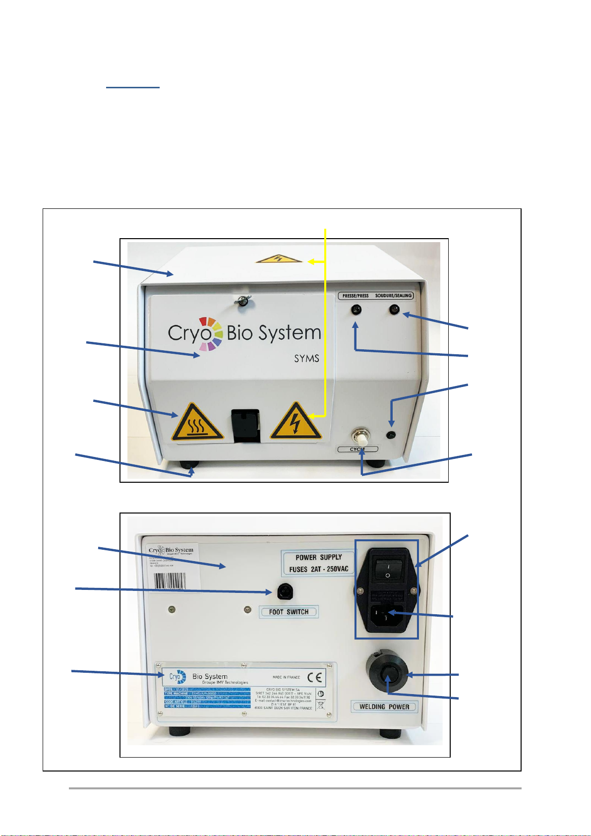
3.2.1 SYMS I manual sealing machine
View of front panel Pic-DE
C.S.C
D3
TRA
D2
D1
Pic-HT
Bu S1
View of rear panel
U0
C-COF
J0
F1, F2
PI C-P1
B-P1


This document may not be reproduced, copied, transmitted or given to a party other than the end-user without the explicit
written authorization of Cryo Bio System.
IFU-000100 [Indice C] [SYMS I] [P. 10 / 18]
Mark
Quantity
Description
Article
reference
C.S.C
1
Complete Upper casing
017179
Bu
4
Black rubber screw stop
016416
C-COF
1
Case frame with inserts
017178
TRA
1
Trap ¼ turn
009844
U2
1
Control pedal
017171
COMP-230v
1
Kit version 230V
017184
C-P1
1
Potentiometer cover
017328
U0
1
Wired mains socket
017168
S1
1
White NO push button
001593
J0
1
Female socket, 3-pin
001394
B-p1
1
Rev counter knob, P/N:90-87742C/ 1rev
001550
Cb1-230V
1
Mains power cord
000939
F1, F2 - 230V
2
Fuse 5x20 2A.T
017173
D1
1
Green LED T1 ¾ 4V
004815
D2
1
Yellow LED T1 ¾ 4V
004814
D3
1
Orange LED T1 ¾ 4V
004813
Pic-DE
2
Electrical Hazard Pictogram
001970
Pic-HT
1
High Temperature Pictogram
001967
F1, F2, PTFE G9
et G22, A19
Spare parts
009848
This document may not be reproduced, copied, transmitted or given to a party other than the end-user without the explicit
written authorization of Cryo Bio System.
IFU-000100 [Indice C] [SYMS I] [P. 11 / 18]
4 ASSEMBLY AND ADAPTATION
Recommendation: On exit from the factory, the SYMS I sealer is configured for use
with 0.3 and 0.5 ml CBSTM High Security straws and High Security Vitrification straws.
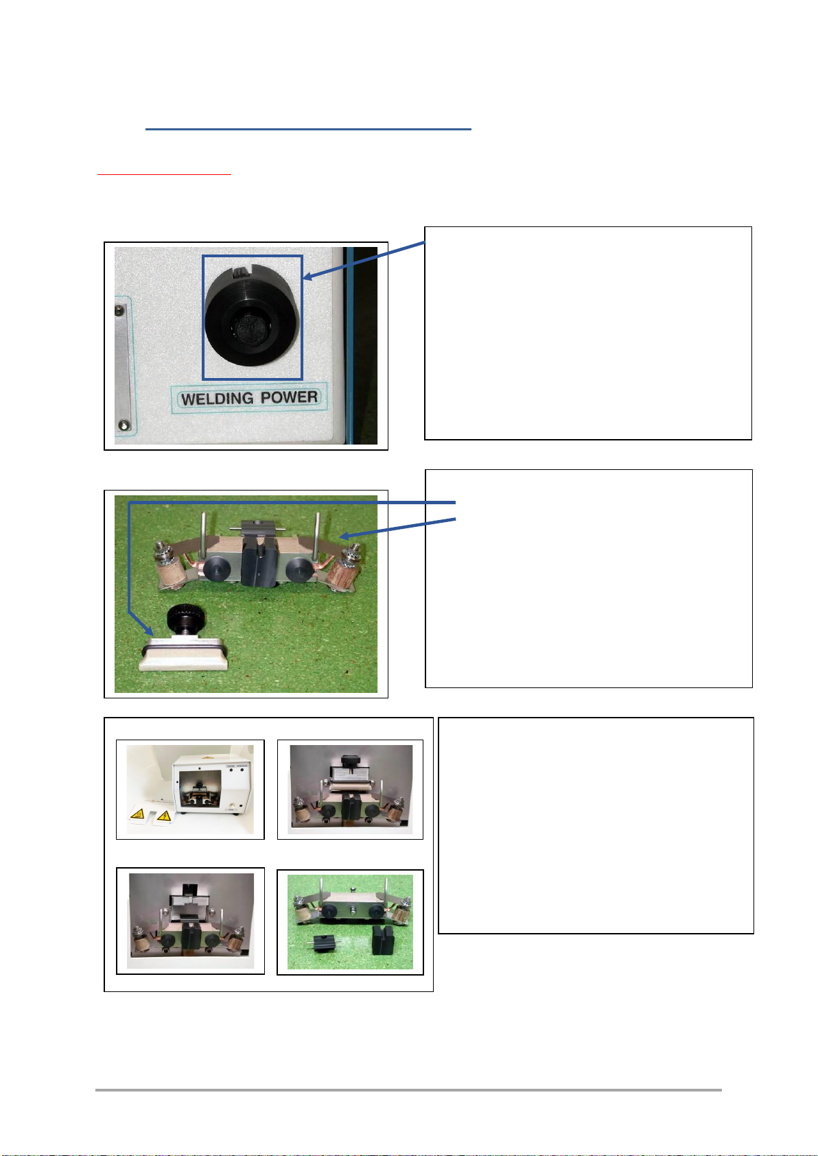
Sealing power
Cleaning
The welding power is pre-set in the factory
and is accessible on the potentiometer on
the rear face.
This setting is specific to the machine.
It is strongly advised not to modify this
setting.
However, and only on the advice of a
maintenance technician, the user may be
called upon to modify this setting if the
sealing is judged inadequate.
The removable parts are:
the cooling jig,
the welding electrode assembly.
They may be removed without difficulty and
decontaminated, provided that there is:
- no immersion.
Decontamination can be carried out with:
- Sanytex diluted to 5% or another equivalent
product,
- a phase of rinsing with distilled water,
- drying with alcohol.
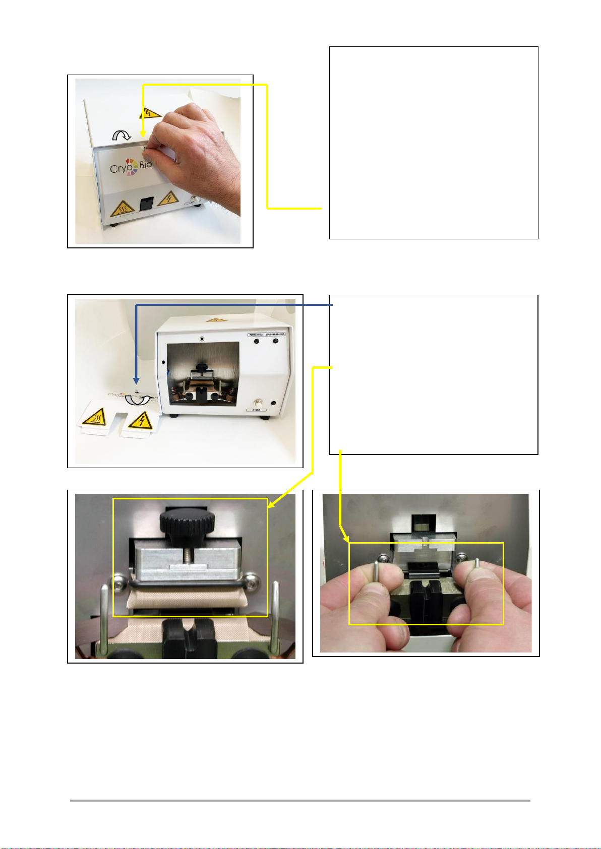
Open the protective flap using rapid nut,
turning it anti-clockwise.
Loosen the knurled nut and remove the
cooling jig.
Remove the welding electrode assembly
- Remove the stop and straw guide by
pulling them out of the electrode assembly.
This document may not be reproduced, copied, transmitted or given to a party other than the end-user without the explicit
written authorization of Cryo Bio System.
IFU-000100 [Indice C] [SYMS I] [P. 12 / 18]
Replacing the bands
Carry out your decontamination
procedure.
Recommendation: Dry the
decontaminated elements before
reassembly.
Reassemble the equipment and
check manually that the cooling jig
comes into contact with the welding
band, otherwise, check the positioning
of the end-stop and adjust the cooling
jig with the help of the knurled nut.
Close the protective flap using the
rapid nut, turning it clockwise.
Open the protective flap using the
rapid nut, turning it anti-clockwise.
Loosen the knurled nut and remove
the cooling jig.
Remove the welding electrode
assembly by pulling it by the levers.
This document may not be reproduced, copied, transmitted or given to a party other than the end-user without the explicit
written authorization of Cryo Bio System.
IFU-000100 [Indice C] [SYMS I] [P. 13 / 18]
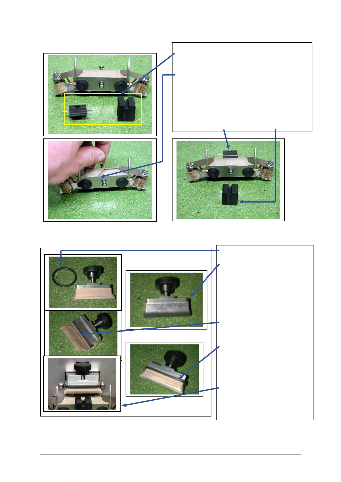
Changing the welding tape band
Changing the cooling jig band
Remove the stop and straw guide by pulling
them out of the electrode assembly.
Remove the adhesive PTFE band covering
the sealing tape.
Cover the sealing tape with the PTFE
adhesive “G9” supplied in the composition.
Make sure that the adhesive is correctly
applied.
Reinstall the end-stop and the straw guide.
Remove the ‘O’ ring weld.
Remove the adhesive PTFE
band covering the cooling jig.
Cover the cooling jig with the
“G22”adhesive PTFE band size
45mm x 30mm supplied in the
composition.
Make sure that the adhesive is
correctly applied.
Reinstall the ‘O’ ring weld.
Reassemble the equipment
and check manually that the
cooling jig comes into contact
to the welding band, otherwise
check the positioning of the
end stop and adjust the cooling
jig with the help of the knurled
nut.

This document may not be reproduced, copied, transmitted or given to a party other than the end-user without the explicit
written authorization of Cryo Bio System.
IFU-000100 [Indice C] [SYMS I] [P. 14 / 18]
Replacing the elastomer mat
Open the protective flap using the
rapid nut, turning it anti-clockwise.
Loosen the knurled nut and
remove the cooling jig.
Remove the ‘O’ ring weld.
Remove the adhesive PTFE
band covering the cooling jig.
Change the elastomer mat
supplied in the composition by
inserting it in the grove of the
cooling jig.
Cover the cooling jig and the
elastomer mat with the “G22”
adhesive PTFE band of size 45
mm x 30 mm supplied in the
composition (apply the adhesive
correctly).
Reinstall the ‘O’ ring weld.
Reinstall the cooling jig, then
check manually that the cooling
jig comes into contact with the
welding band, otherwise, check
the positioning of the end-stop
and adjust the cooling jig with
the help of the knurled nut.
Close the protective flap.

This document may not be reproduced, copied, transmitted or given to a party other than the end-user without the explicit
written authorization of Cryo Bio System.
IFU-000100 [Indice C] [SYMS I] [P. 15 / 18]
5 PROCEDURE
5.1 Operation of the individual straw sealer
The sealer does not require any heating up time. It can be used without any problem
in a laminar flow hood or a controlled temperature environment, because the
thermal pulse welding principle limits the release of calories.
However, after a series of 10 seals, it is recommended to comply with a rest time
of five minutes in order to obtain optimum operation.
Connection
Sélection chauffe
Connect the mains power cable “Cb1”to
the socket in the input filter “U0” identified by:
POWER SUPPLY
For use with the control pedal (available as
an option), connect the cable of the control
pedal to the socket “J0” identified by:
FOOT SWITCH
–Set the “U0”main switch to the ‘ON’ position.
–Check that the green “D1”Power On indicator is lit.

This document may not be reproduced, copied, transmitted or given to a party other than the end-user without the explicit
written authorization of Cryo Bio System.
IFU-000100 [Indice C] [SYMS I] [P. 16 / 18]
Starting the cycle
Remark: Each pressing of the pushbutton or the control pedal causes a welding
cycle.
Opening the flap
Pressing the white “S1”pushbutton or
the “U2”control pedal (available as an
option) activates a welding cycle.
The opening of the protective flap
causes:
the stopping of the cycle,
the clocking of the controls.
The equipment remains switched on.
This is indicated by the presence of the
green Power On indicator
The welding cycle lasts 4 seconds
and is indicated by the yellow
indicator.
The orange indicator corresponds to
the thermal pulse.

This document may not be reproduced, copied, transmitted or given to a party other than the end-user without the explicit
written authorization of Cryo Bio System.
IFU-000100 [Indice C] [SYMS I] [P. 17 / 18]
6 MAINTENANCE
6.1 Precautions
Maintenance on the individual straw welding machine must be carried once the
machine has been powered down. In case of an accident, Cryo Bio System cannot
be held responsible.
6.2 Maintenance
The main mechanical and electrical parts of the welding machine do not require
any particular maintenance.
Repairs must be carried by a specialist, approved by Cryo Bio System.
However, it is recommended to regularly clean the welding jaws, particularly if they
got accidentally dirty when welding the straws.
If burn marks show on the PTFE bands, they need to be replaced (see composition).
6.3 Transport and storage
Disconnect the equipment from the mains.
To prevent damage, always store and transport the equipment and related parts
in their original packaging.
Store the equipment in a dry place.
When transporting the SYMS I, avoid shocks or brisk movements.
6.4 Recycling of worn parts
Please dispose of old equipment (transformer, electromagnet) at a
specialized center.
Separate the old pieces of equipment as per their composition: metal, plastic,
etc…
6.5 Non-responsibility clause
The Cryo Bio System company cannot be held responsible for any damage
due to external effects or to inappropriate handling or usage.
See the paragraphs on scope of application and electrical specifications on page 2
of these instructions for use.

This document may not be reproduced, copied, transmitted or given to a party other than the end-user without the explicit
written authorization of Cryo Bio System.
IFU-000100 [Indice C] [SYMS I] [P. 18 / 18]
7 Contact
Cryo Bio System
ZI n°1 Est
61300 SAINT OUEN SUR ITON
02.33.34.64.44
support@imv-technologies.com
Table of contents
Popular Food Saver manuals by other brands


BonsenKitchen
BonsenKitchen VS3906 Operation instructions

All American
All American 1502 Operator's manual

Silvercrest
Silvercrest 277100 operating instructions

Silvercrest
Silvercrest 397059 2110 operating instructions

Proficook
Proficook PC-VK 1146 instruction manual

Silvercrest
Silvercrest 71770 operating instructions


