All American 1502 User manual

OPERATOR’S MANUAL
MODEL 1502 & 7502
CAN SEALER
WISCONSIN ALUMINUM FOUNDRY CO.
1931 SOUTH 14TH STREET
MANITOWOC, WI 54220 USA
920-682-8627 FAX: 920682-4090
email: customerrelations@wafco.com
web page: www.allamerican-chefsdesign.com

2
Table of Contents
Page 3 - Introduction & Getting Started
Page 4 - Parts Diagram
Page 5 - Maintenance
Page 6 - Adjustments & Seam Gauge
Page 7 - Adjustments Continued
Page 8 - Parts Picture List
Page 9 - Parts List
Page 10 - Warranty Information

3
INTRODUCTION
This can sealer was thoroughly inspected and tested at the factory before shipment. Immediately
upon receipt, carefully check the can sealer for damage before using it. Do not operate the can sealer
if it is damaged; call (920)-682-8627 for further instruction.
The 1502 & 7502 typically comes with the CY-10 Chuck and the S-203 Base Plate. These are designed
and set up to seal a No. 10 can. A sample can was used to set up the machine and was locked in place
during shipping to help protect the machine. Prior to removing the container, lower and raise the
base plate by turning the Can Lifter Handle as far as possible to the left and then back to the right a
few times. Pay attention to the amount of pressure you have to apply to the Lifter Handle when
locking the can into place. It is good to develop a feel for the amount of base plate pressure required
to properly seal a can. Cans with a bigger or smaller diameter will require a different size Chuck and
Base Plate. Height adjustment with spacers is necessary before attempting to seal other size cans.
GETTING STARTED
1. The sealer can be firmly attached to a table or bar using the four bolt holes (cast into sealer
base) to bolt down the sealer. If that isn’t possible, you can use a C-clamp to attach the sealer
to a bench top.
2. For operation, the seaming lever rivets (CY-22R) should be in the number 10 hole of the cam
roller arms (S-222). (They come in the number 10 hole for shipping.)
3. Lower the Base Plate (S-203) by turning the Can Lifter Handle (CY-10) as far as possible to the
left.
4. Place lid on filled can and set can on Base Plate (S-203).
5. Raise can until it is clamped firmly between the Base Plate and Chuck by turning Can Lifter
Handle (CY-10) as far as possible to the right until handle locks itself against the Frame (S-201).
The can is now ready to be sealed.
6. Turn the flywheel until the first operation roller touches the can, continue to turn until the
first operation roller pulls away from the can. This hooks the lid to the can. Keep turning the
flywheel until the second operation roller touches the can; continue to turn until the second
operation roller pulls away from the can. This finishes the seal. (You will turn the flywheel a
total of 18 times.)
7. When both arms are away from the can, pull can lifter handle toward you and remove can.
8. Wipe down the machine frequently to prevent buildup of foreign material.

4
PARTS DIAGRAM
Roller Bearing Lever
CY-9S & CY-9F
Seaming Roller Pin
CY-18S & CY-8F
Seaming Lever
S-208
Adjusting Lever
S-224
Cam Roller Lever
S-222
Operation Roller
CY-14& CY-15
Lock Screw for Roller Bearing
CY-9LS
Adjusting Screw and Lock
Nut CY-24AS & CY-24LN
Flywheel
Complete
S-255
Worm Wheel Cover
S-202
Frame for 1502
S-201
Can Lifter Handle
CY-10
Chuck Holder
Bushing
CY-19
Front Gear
Cover
CY-65
No. 10 Chuck
Base Plate Shaft
S-232S OR
S-232L
Compression
Spring
CY-34
Chuck Holder Bushing
CY-19
Rivet for Cam Roller
CY-22R
Seaming Lever Pin
CY-17
Base Plate
S-203

5
MAINTENANCE
Quarterly Maintenance Schedule
1. Remove Base Plate and oil Ball Bearing on the underside with food grade lube oil.
2. Remove Can Lifter Handle; oil brass stem and where Handle comes in contact with Frame. (Use food grade oil)
3. Put food grade white petrolatum on all of the teeth of the Cam Worm Wheel located behind the Cam Worm
Wheel Cover.
4. Put food grade white petrolatum on the teeth of the Bevel Gear located behind the Front Gear Cover.
Daily Maintenance Schedule: Use food grade lube oil at each arrow below.
1
2
4
3
3
2
Oil Roller
Oil Hole in CY-2
Oil Roller
Oil Hole
Oil Hole
Oil Hole

6
ADJUSTMENTS & SEAM GAUGE
Check the adjustment of the Seaming Rolls occasionally. First
check the height adjustment as follows: When Chuck (A in sketch)
is held up tightly against the Ball Bearing (S-201), the underside of
the top flange on the Seaming Roll (B in sketch) must fit closely on
top of Chuck (A). To make adjustments, push the Cam Roller Lever
(S-222) toward Chuck until Seaming Roll touches the Chuck.
Slightly loosen Screw (CY-9LS) which is “C” in sketch, push down on
Roller Bearing Lever that contains Seaming Roll (B) until top flange
of Seaming Roll (B) rests on top of Chuck (A). Now tighten Screw
(CY-9LS) which is “C” in sketch as tight as possible.
This adjustment should be made on both 1st and 2nd Operation
Rolls. After height adjustment has been made, use the Seam
Gauge which is for checking the seam on any standard size can.
Use the seam gauge as follows: Remove the Rivet (CY-22R) on the Second Operation Cam Roller
Lever (S-222). The second operation is on the right side if you are facing the front of the machine.
Run an empty can in the machine to seal the First Operation. Remove the can and slip the Gauge
over the seam. The groove marked “1st” should slide over seam on can. The seam will not fill the
entire length of the groove but the Gauge should slip on far enough so that it touches the can cover.
If groove in Gauge will not slip over seam, tighten First Operation Roller (CY-14) by loosening Lock Nut
(No. CY-24LN) and turning Adjusting Screw (No.CY-24AS) not more than a quarter turn to the right. If
the groove in Gauge is loose on the seam, turn the Adjusting Screw to the left. Repeat above
operation with another empty can until Seam Gauge fits over seam correctly. When first operation
seam is correct, change the Rivet (CY-22R) from the First Operation Levers to the Second Operation
Levers and adjust the Second Operation Roller in the same manner as the First Operation Roller using
the can that has a proper first operation roll seam. The groove in the Seam Gauge marked “2nd” is
used when adjusting the Second Operation Roller (CY-15). Be sure to tighten the Lock Nuts (No. CY-
24LN) after adjusting each roller.
If it is necessary to operate sealer without a can in place, remove Chuck (S-222) to prevent damage
to it and Seaming Rolls.

7
Instructions for Setting & Adjusting Senior Can Sealers
For 202, 208, 300, 301 and 303 Diameter Cans
To set up a Senior Can Sealer for “special” size cans, you will have to take the following steps in order to
achieve a proper seal:
Sealing Cans With a 202 or 208 Diameter:
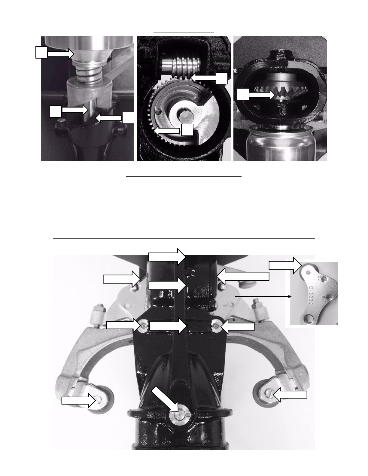
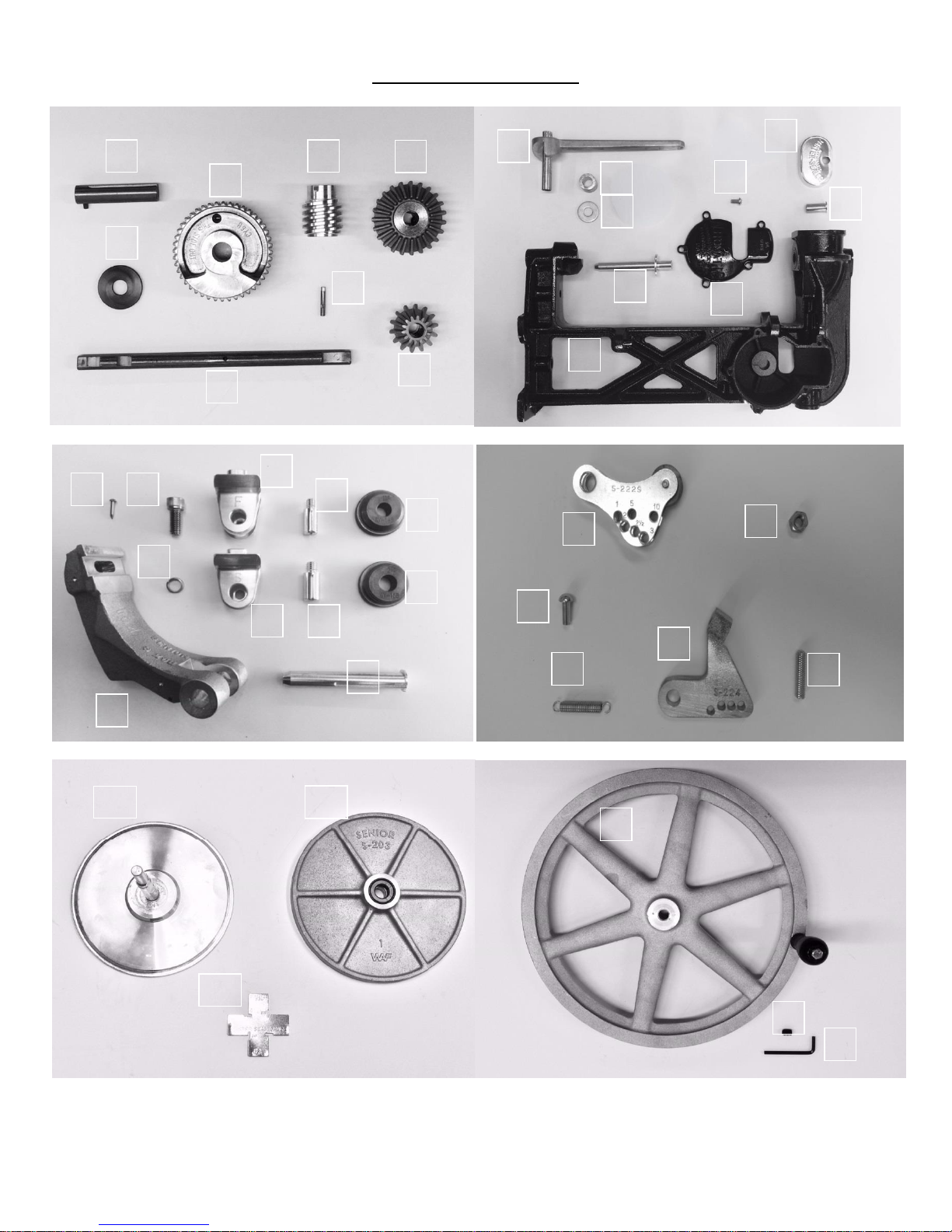
1. Remove both CY-22R Rivets from the S-222 Cam Roller Lever and S-224 Adjusting Levers.
2. Remove existing chuck from sealer and replace with proper chuck for diameter desired.
3. Adjust the height washers so that you obtain proper tension and height of cans to be sealed.
Note: you may have to use a special base plate with grooves machined out in order to fit your
can.
4. Replace CY-22R Rivet in the hole labeled “1” on the S-222 Cam Roller Lever and corresponding
hole on the S-224 Adjusting Lever. Note: Only replace the CY-22R Rivet on the first operation
(the first operation is on the opposite side of the machine when the flywheel of the machine is
at your right).
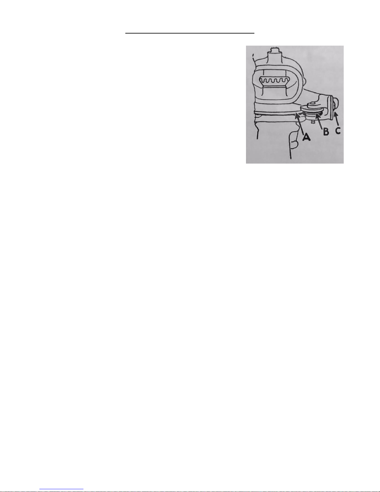
5. With a wrench, loosen the CY-24LN Lock Nut so that you can tighten the tension of the CY-14
Seaming Roller by turning the CY-24AS Adjusting Screw clockwise. We suggest that you
tighten the CY-24AS one-quarter turn at a time until can seam fits into CY-38 Seam Gauge
properly. After this is obtained, tighten CY-24LN Lock Nut again.
6. Remove CY-22R Rivet from first operation and replace rivet in No. “1” hole on second
operation side. Note: The second operation is on the side you are facing.
7. Repeat step “5” until properly adjusted. Then replace CY-22R Rivets in the No. “1” holes on
both sides and can sealer is set up to seal your desired can.
Sealing Cans With a 300, 301 and 303 Diameter:
1. Same as for 202 and 208 cans.
2. Same as for 202 and 208 cans.
3. Same as for 202 and 208 cans.
4. Same as for 202 and 208 cans except that the CY-22R Rivets should be placed in the hole
labeled “2”.
5. Same as for 202 and 208 cans. If you were sealing a 202 or 208 diameter can on this machine
previously, you may have to loosen the tension instead of tighten.
6. Same as for 202 and 208 except that the CY-22R Rivet should be placed in the hole labeled
“2”.
7. Same as for 202 and 208 with the exception as listed in step “5” for sealing 300, 301 and 303
cans.

8
PARTS PICTURE LIST
18
19
20
27
21
22
23
24
28
26
25
29
33
32
31
34
30
1
2
3
4
5
6
7
8
10
11
16
17
15
38
12
14
13
9
39
40
35
36
37

9
PARTS ILLUSTRATION LIST
PICTURE
Number
1
2
3
4
5
6
7
8
9
10
11
12
13
14
15
16
17
18
19
20
21
22
23
24
25
26
27
28
29
30
31
32
33
34
35
36
37
38
39
40
PART
Number
CY-26
S-206
CY-7
S-204
CY-25W
CY-25D
S-225F
S-205
CY-10
CY-34
HW
S-265
CY-2S
CY-19
S-232S
S-202
S-201
CY-1E
CY-9LS
CY-9LW
CY-9F
CY-9S
CY-18F
CY-18S
CY-14
CY-15
S-208
CY-17
S-222
CY-24LN
CY-22R
CY-35
S-224
CY-24AS
S-286
S-203
CY-83
S-255
S-255S
S-255SW
DESCRIPTION
Worm Wheel Shaft
Cam Worm Wheel
Worm Gear
Bevel Gear w/ Ball Lock
Worm Shaft Fiber Washer
Pin for Worm Shaft
Worm Shaft
Bevel Pin Gear
Can Lifter Handle
Base Compression Spring
Various Height Washers
Front Gear Cover
Cover Plate Screw
Chuck Holder Bushing (Top)
Base Plate Short Shaft or (S-232L-Long Shaft)
Worm Wheel Cover
Frame for 1502
Escutcheon Pin
Lock Screw for Roller Bearing
Lock Washer for Lock Screw
Roller Bearing Lever-First
Roller Bearing Lever-Second
Seaming Roller Pin-First
Seaming Roller Pin-Second
First Operation Roll
Second Operation Roll
Seaming Lever-First or Second
Seaming Lever Pin
Cam Roller Lever - Complete
Lock Nut for Adjusting Screw
Rivet for Cam Roller & Adjusting Levers
Seaming Lever Spring
1 Adjusting Lever –Works for 1st or 2nd
Adjusting Screw for Adjusting Levers
No. 10 Chuck
Base Plate with Ball Bearing
Seam Gauge
Flywheel Complete
Flywheel Set Screw
Set Screw Wrench
To order parts, please call Wisconsin Aluminum Foundry Co. at 920-682-8627
or e-mail [email protected]

10
ALL AMERICAN
AUTOMATIC MASTER CAN SEALER
LIMITED WARRANTY
This quality Automatic Master Can Sealer is designed and manufactured to provide many years of
satisfactory performance under normal use. Wisconsin Aluminum Foundry guarantees to the original
owner that should there be any defects in material or workmanship during the first ninety (90) days
after purchase, we will repair or replace it, at our option. This warranty does not apply to damage
caused by shipping. To obtain service under the warranty, please do the following:
1) Call the Customer Service Department to obtain a Return Authorization (RA) Number.
Items returned without a Return Authorization Number will be refused.
2) Return can sealer, shipping prepaid with sales receipt, RA Number and a description of the
claimed defect to:
WISCONSIN ALUMINUM FOUNDRY CO., INC.
CONSUMER PRODUCTS DIVISION
1931 SOUTH 14th STREET / PO BOX 246
MANITOWOC, WI 54220
PHONE: 920-682-8627 FAX: 920-682-4090
Return transportation will be prepaid on all can sealers under warranty. Repairs made after the
warranty has expired will be billed at the current repair costs.
We want you to obtain maximum enjoyment from using this quality can sealer and we ask that you
take the time to read and follow the operating instructions. Failure to follow instructions, damage
caused by improper replacement parts, abuse, or misuse will void this warranty.
This warranty gives you specific legal rights, and you may also have other rights which vary from state
to state. This is Wisconsin Aluminum Foundry’s guarantee to you and is being made in place of all
other express warranties.
Important - please read: Any alterations, modifications or changes of any type
made to the can sealer or to any component thereof will void this warranty.
This manual suits for next models
1
Table of contents
Other All American Food Saver manuals