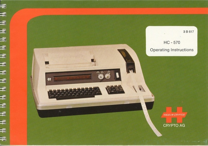
CRYPTO AG CRYPTOMATIC HC-530 User manual

SNOiionaiSNi ONiivaado
QNV NOIlVmVlSNI
9eS-OH/0C9-OH
JDUVIAIOldAUO
9t?6ae
9V OldAHO
SOldAUO-NmOVH


3B945 HAGEUN-CRYPTOS
CRYPTO AG
WARNING
VOLTAGES INSIDE THE HC-530/535 CIPHERING TERMINALS CAN CAUSE DEATH OR
INJURY. UNDER NO CIRCUMSTANCES SHOULD THESE UNITS BE OPENED WITHOUT
FIRST DISCONNECTING THE POWER CORD FROM THE MAINS SUPPLY. NEVER APPLY
POWER TO A UNIT IF IT IS OPEN.
WARNING
NEVER ALLOW A SHORT CIRCUIT TO OCCUR ACROSS THE TERMINALS OF THE REMOV
ABLE NICKEL-CADMIUM (NI-CD) ACCUMULATOR OF THE HC-530/535. THE LOW IN
TERNAL IMPEDANCE OF THE ACCUMULATOR WILLALLOW HIGH CURRENTS TO BE THEN
PRODUCED, WHICH CAN HEAT AND MELT CONDUCTORS, PRODUCING BURNS, FIRE
HAZARDS AND EQUIPMENT DAMAGE. FURTHER, SINCE NI-CD ACCUMULATORS CONTAIN
HIGHLY-POISONOUS CADMIUM, NEVER DISPOSE OF WORN-OUT ACCUMULATORS IN THE
GARBAGE, NEVER OPEN THEM AND NEVER BURN THEM. RATHER ALWAYS RETURN THEM
TO CRYPTO AG FOR RECYCLING.
CAUTION
BEFORE CONNECTING THE LINE CORD TO YOUR AC MAINS SUPPLY, ENSURE THAT
THE VOLTAGE SELECTOR SWITCH (FIGURE 3.1) IS SET TO YOUR LOCAL SUPPLY
VOLTAGE VALUE (110 OR 220 VAC) NOTE: THIS CAUTION DOES NOT APPLY IF A
DC CHARGER MODULE PSB-530 IS BEING USED; IT HAS NO VOLTAGE SELECTOR
SWITCH.
EMERGENCY CLEAR OF BASIC KEYS
TO DESTROY THE SECRET BASIC KEYS, ENTER
CTRL R CTRL B CTRL X Y
* PRESS THESE KEYS SIMULTANEOUSLY.
TYPE DESIGNATION
THE HARDWARE VERSION (HWV) IS SPECIFIED BY THE THREE DIGITS FOLLOWING
HC-530- (OR HC-535-) ON THE METAL NAMEPLATE OF YOUR HC-530/535. REFER
TO SECTION 6.4.1 TO OBTAIN THE SOFTWARE VERSION (SWV). THIS DOCUMENT IS
VALID FOR HWV = 2XX AND SWV = 02XX WHERE X CAN BE 0 TO 9.

3B945
CRYPTO AG
CONTENTS
II
Page
GENERAL 1-1
1.1 DESCRIPTION
1.2 APPLICATIONS
1.3 CONSTRUCTION
1-1
1-2
1-2
1.3.1 KEYBOARD
1.3.2 DISPLAY
1.3.3 PRINTER
1.3.4 SERIAL INTERFACE
1.3.5 COUPLERS
1-2
1-3
1-4
1-4
1-5
1.3.5.1 ACOUSTIC COUPLER
1.3.5.2 GALVANIC COUPLER
1-5
1-5
1.3.6 POWER SUPPLY
1.3.7 ACCESSORIES
1.3.8 OPTIONS
1-6
1-7
1-9
SPECIFICATIONS 2-1
2.1 TECHNICAL DATA HC-530/535
2.2 SYSTEM SPECIFIC PARAMETERS
2.3 CRYPTOLOGY
2.4 ENVIRONMENTAL CONDITIONS HC-530 ONLY
2.5 ENVIRONMENTAL CONDITIONS HC-535 ONLY
2.6 MECHANICAL DATA HC-530/535
2-1
2-5
2-5
2-6
2-7

3B945
HAGEUN-CRYPTOS
CRYPTO AG III
3. INSTALLATION
Page
3-1
3.1 UNPACKING
3.2 PACKING
3.3 COMMISSIONING
3-1
3-1
3-2
4. OPERATION
4.1 GENERAL OPERATING INFORMATION
4-1
4-1
4.1.1 REMOTE CONTROL VIA SERIAL INTERFACE 4-4
4.2 ITOR MODE (COMMAND MODE 4-4
4.3 VARIABLE PARAMETER (VP) PROGRAMMING 4-5
4.3.1 INITIAL PROGRAMMING OF VARIABLE PARAMETERS (VP
4.3.2 MODIFICATION OF A VALID VP COMBINATION
4.3.3 CLEARING THE VP DATA
4.3.4 TWO VARIABLE PARAMETER COMBINATIONS
4.3.5 STATION IDENTIFICATION (ID) FOR SELECTIVE CALL
4-7
4-7
4-9
4-10
4-11
4.4 BASIC KEY (BK) MODE 4-11
4.4.1 BASIC KEYS 4-12
4.4.1.1 FEATURES FOR THE BASIC KEYS
4.4.1.1.1 "D" FOR BIGRAM DISPLAY
4.4.1.1.2 "E" FOR BASIC KEY ENTRY
4.4.1.1.3 "M" FOR MASTER KEY SELECTION
4.4.1.1.4 "C" FOR CANCELLING BASIC KEYS
4-12
4-13
4-14
4-15
4-16
4.4.2 BASIC KEY EMERGENCY CLEAR 4-17

HAGEUN-CRYPTOS
3B945 ■■IV
CRYPTO AG
Page
4 . 5 TEXT INPUT MODE 4-18
4 . 5 . 1 C L E A R I N G T H E E N T I R E T E X T F R O M M E M O R Y 4 - 1 8
4.5.2 SELECTION OF INPUT MODE WITH KEYBOARD OPERATION 4-19
4.5.3 TEXT INPUT MODE WITH SERIAL INTERFACE 4-19
4.5.4 COUPLER RECEPTION 4-20
4.5.4.1 INTRODUCTION 4-20
4.5.4.2 AUTOMATIC OUTPUT PROCESS 4-20
4.5.4.3 MANUAL INTERRUPTION OT THE COUPLER AUTO
MATIC OUTPUT PROCESS 4-22
4.5.4.4 CLEARING THE RECEIVING MEMORY 4-23
4.5.4.5 RECEIVING WITH ACOUSTIC COUPLER 4-23
4.5.4.6 RECEIVING WITH GALVANIC COUPLER 4-25
4.5.4.6.1 GALVANIC COUPLER AND RADIO
OPERATION 4-28
4.5.4.6.1.1 CONNECTIONS FOR RADIO 4-28
4.5.4.6.1.2 OPERATION AT RADIO RECEIVER 4-31
4.5.4.6.1.3 OPERATION AT RADIO TRANSMITTER 4-32
4.5.4.6.1.4 RADIO CALIBRATION 4-32
4.6 PRINTER MODE 4-33
4 . 7 S E R I A L O U T P U T ( O U T P U T O F M E M O R Y C O N T E N T S ) 4 - 3 4
4 . 7 . 1 S E L E C T I O N O F S E R I A L O U T P U T M O D E 4 - 3 5
4.8 CIPHERING 4-35
4.8.1 CIPHERING BY PRINTER 4-37
4.8.2 CIPHERING BY DISPLAY 4-38
4 . 8 . 3 C I P H E R I N G V I A T H E S E R I A L I N T E R F A C E 4 - 3 8
4.8.3.1 MESSAGE-SWITCH NETWORKS 4-39

Z-g S»33H3 H3H10 £'9
X-9 AlIlVnQ SNIlNIbd tiOOd Z*S
X-9 0NIti3HdI33Cl U313V 1X31 Q3"iatiV9 X*9
I-g S>I33H3 *9
99-17 SlPdinO 1X31 NIVId ZT*l7
179-17 bV3"13 A0N39H3W3 AH0W3W XT'*
179-17 1X31 9NI9NVH3 S'OT'fr
£9-17 N0I1H3SNI 1X31 l7*0I*t7
£9-17 N0I13130 1X31 £*0X*17
ZS-17 H3tiV3S 1X31 Z*0X*17
29—(7 1X31 30 9NIQV3d VOVIf
617-17 300W d01I03 OT*"b
Z17-17 NOIIVRNIINOO 9NIti3HdI03a 17*6*17
Z 1 7 - 1 7 3 3 V J t i 3 1 N I 1 V I t t 3 S 3 H 1 V I A 9 N I U 3 H d I 0 3 a £ * 6 * 1 7
917-17 AVldSia HUM 9NIti3HdI03a Z'6*l7
917-17 *J31NItid HUM 9NIU3HdI33a X*6'17
frt-f 3Q0W 9Niy3HdI33Q 6* 17
Z17-17 T1V-01-ST1V0 ONV Sdfl 11V3 df!0d9 Z*S*8'l7
Z17-17 11V3 3AI13313S H03 N0I13333S dA X*9*8*17
Xt7-17 11V3 3AI13313S 9*8*17
6£"17 (3INVA1V9 ONV OUSflOOV)
H31dn03 3H1 VIA ONItGHdlO K8*l7
a6ed
9V OldAUO
SQldAHO-NmOVH
9l769£

3B945
HAGEUN-CRYPTOS
CRYPTO AG
VI
Page
6. MAINTENANCE PROCEDURES 6-1
6.1 REPLACING PRINTING PAPER
6.2 HANDLING OF THE THERMO PAPER
6.3 ACCUMULATOR MAINTENANCE
6.4 DIAGNOSTIC SOFTWARE (OPTION)
6-1
6-3
6-4
6-5
6.4.1 DIAGNOSTIC TEST PROGRAM 6-7
6.4.1.1 GENERAL TEST DETAILS
6.4.1.2 FAULT SIGNALIZATION
6-9
6-14
6.4.2 FUNCTIONS DIAGNOSED BY DIAGNOSTIC TEST PROGRAM 6-15
6.4.3 FUNCTIONS NOT DIAGNOSED BY DIAGNOSTIC TEST PROGRAM 6-16
APPENDIX Al CASES
APPENDIX A2 MODULE BLOCK DIAGRAM
APPENDIX A3 SERIAL INTERFACE PIN ASSIGNMENTS
APPENDIX A4 GALVANIC COUPLER PIN ASSIGNMENTS
APPENDIX A5 GALVANIC COUPLER CABLE AND PLUG (RADIO
APPLICATIONS)
1-1

HAGEUN-CRYPTOS
3B945 1-1
CRYPTO AG
1. GENERAL
1.1 DESCRIPTION
The CRYPT0MATIC®HC-530/535 is a universal ciphering terminal for
mobile or stationary use. It serves primarily for the ciphering
and deciphering of text in the off-line mode, yet can also be used
for ciphered transmission directly over the line via serial or
coupler outputs.
The unit is available in a civilian version (HC-530), which comes
in a compact elegant Samsonite attache case or in a military ver
sion (HC-535), which comes in a ruggedized military-type case
(Appendix 1). Both units can be operated without being removed
from their cases.
The various text input and output possibilities as well as a
powerful microprocessor system give the units an exceptional
flexibility. Operation of the units is simple and logical.
The units will operate, due to their rechargeable, gas-tight
nickel-cadmium accumulator (batteries), for up to 5 hours in
dependently of the mains supply. A removable AC (or DC) charger
module allows mains buffer or charging operations at all times.
The integral printer can also be continuously operated from the
accumulator if ever necessary for a duration of approximately
0.8 hours.
The robust metal housing of the HC-530/535 gives excellent EMC
protection. The standard text memory is 2000 characters and an
optional version with 6000 characters is available. An independent
6000 character receiving memory is available for coupler recep
tion.

HAGEUN-CRYPTOS
3B945 1-2
CRYPTO AG
1.2 APPLICATIONS
The HC-530/HC-535 allows ciphering and deciphering of secret mes
sages. Messages may be transferred via the acoustic coupler, gal
vanic coupler or serial interface. The serial interface permits
output/input via various types of peripheral equipment such as a
tape punch/reader or a telegraph interface for a teleprinter.
1.3 CONSTRUCTION
The HC-530/535 consists of the following plug-in assemblies
(modules), Appendix A2:
- Alpha-numeric keyboard and display
- Thermo-printer
- Serial interface
- 5 printed circuit (PC) boards in EURO-format
- Couplers (acoustic and galvanic) with common modem
- Power converter PC board for internal voltages
- AC charger module
- A c c u m u l a t o r ( i . e . , r e c h a r g e a b l e b a t t e r y ) p a c k .
The connections between modules are provided mainly by ribbon
cables.
1.3.1 KEYBOARD
The keyboard of the HC-530/535 has four rows. An n-key rollover
function permits fast and error-free inputting. Each key is equip
ped with a mechanical contact which locks the key during opera
tion. The contact is gold plated and is located in a dust-proof
housing. The key caps are removable. The code correlation is pre
set in a matrix. All control and operating commands are entered
via the keyboard (by pressing the control key CTRL and another key
simultaneously).

(sindui. jo^) joquinu uoj.q.B3j4Lquapi N
apow ^LneJ 3
SpOUl aq.BOO[ JO^.i.p3 13
apoui o6upl|o ao^Lpg 33
apow q.aasuj. jo^lp3 13
apow Joq.j.p3 3
OpOUJ qS31 1
apoui 6uj.jaqdj.oaQ a
apoui 6uuai|dL3 3
(A~JOUiaui iuojj. axoq.) apoui qndq.no Lp.LJ3S S
(Ajouiaui uiojj. Txaq.) apoui 6uj4UUd d
apoui q.ndui q.xai I
OpOlU A*9)| DLSBQ g
apoui (puBiuuioo) joq.LUOW W
apoui 6uLUiuieu6oud ueq.auiBJBd 9Lqej.uBA A
apow 6uj.q.Bjado (snq.Bq.s)
Joq.eoj.pui ^POW
:sMOL[Oi sb
aje sapow asaqi *9£9/0£9-3H 9M1 i° apow q.ua.wno aqq. saq.B0j.puL X"B[d
-SLp aqq. ±o q.j.a[ jbj. aqq. q.B mopulm v •uoj.q.Biuuo^uj. puB suoLq.onuq.s
-Uj, 6uL^Bjado SMoqs puB indino ixaq. sap.LAOJd 'induL ixaq. 6uunp
>|oaqo b sb saAjas (031) A~BLdsj.p LnsA"J0 p lnb l l uo.nj.sod 017 ©Ml
AVldSIQ Z'£'\
£-1 9V OldAUO gt768£
saidAHO-Nraom

HAGEUN-CRYPTOS
3B945 1-4
CRYPTO AG
The following warning signals are also shown (flashing display):
- an asterisk (*) alternating with text (indicates memory nearly
full)
- Blank display alternates with text (indicates that the Ni-Cd
accummulator is nearly discharged).
1.3.3 PRINTER
A robust thermo-printer is located in the HC-530/535. Printing is
in transverse format, i.e., along the long dimension of the
thermo-paper strip, providing clear easily-readable text. The
printer consists of a transport roller, a thermo-head with 100
printing points and a stepping motor with gearing. A pushbutton
for paper feed is located under the lid covering the printer. When
this pushbutton is operated the printer head is lifted and
mechanical pressure released. Paper feed can only be carried out
when the unit is in monitor mode (status M).
1.3.4 SERIAL INTERFACE
The serial interface serves for serial data input and output as
well as for test purposes. The asynchronous data input and output
signals are available in V28/V24 levels. These signals as well as
other signals are available on the interface plug in TTL level
(CMOS 5 volt). In addition, the supply voltages are fed to the
interface plug for test purposes. Serial data transmission speeds
can be selected from 50 to 1200 baud. It is also possible to em
ploy external clocks, whereby 16-fold bit rate can be applied.
The bit rates for input and output can be independently preselect
ed by means of an operator-controlled variable parameter program
ming mode. It is possible to work in either 5 bit Baudot code or
in 8 bit ASCII. In 8 bit code there are various format possibili
ties: with and without parity, 1 or 2 stop-bits as well as 7 or 8
data bits.

HAGEUN-CRYPTOS
3B945 ■■1- 5
CRYPTO AG
The serial interface pin assignments are given in Appendix A3.
1.3.5 COUPLERS
Various types of coupler operation are programmable
- Normal or
one time: 240 baud (48 characters per second)
- FEC (or
redundant): Multiple transmission with multiple decision
during reception. In this way interference inter
ruptions of up to approximately 0.5 seconds can be
bridged.
- Selective
Call: Individual addressing or group calling
1.3.5.1 ACOUSTIC COUPLER
The acoustic telephone coupler allows transmission of ciphered
messages over telephone lines. The design of the telephone coupler
allows coupling to practically all current types of telephone hand
sets. Transmission takes place synchronously.
1.3.5.2 GALVANIC COUPLER
The galvanic coupler is an electronic interface which allows tele
phone and radio communications with the HC-530/535 to take place
electrically, i.e., without conversion to an acoustic signal. The
galvanic coupler is supplied as part of the acoustic coupler op
tion and uses the same modem.
Switchover from acoustic to galvanic operation occurs automati
cally as soon as the galvanic coupler is connected to a telephone
interface (such as, e.g., the TFG-530 Telephone/Galvanic Switch
over Interface) or to a radio transmitter (both covered in Chapter
4).

HAGEUN-CRYPTOS
3B945 ■■1- 6
CRYPTO AG
The galvanic coupler allows data to be transferred completely
electrically thus avoiding background noise sources which can
negatively influence acoustic coupler reception.
The galvanic coupler pin assignments are given in Appendix A4.
1.3.6 POWER SUPPLY
The mains supply feeds the charger module of the HC-530/535. (By
"mains supply" is meant the 110/220 VAC source for the standard AC
charger module or the 10 to 30 VDC source for the optional PSB-530
DC charger module.) The HC-530/535 charger module works with a 24
volt nickel-cadmium (Ni-Cd) accumulator in buffer operation as
follows: The accumulator will charge regardless of whether the
HC-530/535 is turned on or off, but only when the HC-530/535 is
connected to the mains supply. When the printer is operating, how
ever, the accumulator helps the charger module supply power to the
printer; the accumulator will thus be discharging somewhat when
the printer is in use. (The accumulator can, of course, supply
power if both operation and printing when the mains supply is not
connected.)
Complete discharging of the accumulator during operation (unit
switched on) is not possible since a monitor control switches out
the accumulator as soon as the terminal voltage drops below appro
ximately 21V. For mains independent operation the unit should be
charged for 12 to 15 hours before use. This gives up to 5 hours of
normal operation or 0.8 hours of continual printing operation.
With a used accumulator these operating times are, of course,
reduced. The accumulator voltage is stepped-down by a power con
verter to provide the internal voltages (see also Section 4.6).
This power converter is equipped with over-current and over-
voltage cut-out devices. The over-current protection is provided
by a fuse. The charger module is also protected by a fuse on the
secondary side. The charger is fitted with a thermal fuse on the
mains side.

HAGEUN-CRYPTOS
3B945 1-7
CRYPTO AG
A separate 4.8V Ni-Cd accumulator protects the basic key and vari
able parameter memories. (This accumulator is mounted on the key
board and display PC board - Appendix A2.)
1.3.7 ACCESSORIES
The HC-530/535 is delivered with the following standard accesso
ries:
- 2 mechanical security keys
- 2 rolls of thermo paper for printing
- 1 cleaning band for the printer
- 1 set of operating instructions (this document)
- 1 plasticized Reference Card
- 1 plasticized Short Form Instructions Booklet
In addition the following accessories are available (Fiqure 1.1):
- TPR-530 Tape Punch/Reader for producing and reading paper
tapes in the 5-bit Baudot code (CCITT No. 2) at 200 baud
- PSB-530 DC Charger Module for a supply voltage of from 10 to
30 VDC
- ATX-530 Teleprinter Interface with built-in power supply and
providing data conversion from the 5V CMOS of the HC-530/535
to a high level 60V, 40ma single-current teleprinter signal.
- PTS-530 Thermo paper (in packs of 25)
- Specially-wired back-back connector cable for test purposes
(i.e., for connecting together two HC-530/535 terminals) and
for connecting the V24 interface of the HC-530/535 to peri
pherals of other manufacturers having an RS-232C interface,
e.q., visual display units (VDU's), standard high-speed
ASCII printers, etc.
- TEA-530 Diagnostic Test Unit for troubleshooting the
HC-530/535 to a module level

3B945 CRYPTO AG 1-1
PTS-530 ADA-530 ATX-530
Thermo-paper HF Link Frequency Teleprinter
Rolls Adjustment Indicator Interface
542.101
TPR-530
Tape Punch/Reader Station
PSB-530
DC Charger Module
Figure 1.1 HC-530/535 Accessories

HAGEUN-CRYPTOS
3B945 CRYPTO AG 1-9
Coupler Cable TFG-530
and Plug Telephone/Galvanic
546.944A : Free End Switchover Interface
Also for radio:
546.674 SE-20
547.899 PRC-77 Ha ndset
547.925 PRC-77 Wi deband
546.816 SYNCAL, H arris, etc.)
Back-Back
Connector
546.945A
TEA-530
Diagnostic
Test Unit
TED-530
Diagnostic
Test Unit
Figure 1.1 continued

HAGEUN-CRYPTOS
3B945 ■■1-10
CRYPTO AG
TED-530 Diagnostic Test Unit for troubleshooting the
HC-530/535 to a component level
TFG-530 Telephone/Galvanic Switchover Interface allowing
manual or automatic connection of the public telephone line
to either the subscriber's telephone or to the HC-530/535
galvanic coupler. This allows unattended receiving station
operation, either ciphered or plain.
Galvanic Coupler Cable and Plug for radio applications
(Appendix A5)
ADA-530 HF Link Frequency Adjustment Indicator for radio
calibration purposes (Section 4.5.4.6.1.4).
1.3.8 OPTIONS
Acoustic/Galvanic Coupler (for telephone and radio
operation)
6000-Character Memory (replaces the standard 2000 character
memory)
Text Editor (for modifying and correcting the memory
contents
Diagnostic Test Software (for unit check and fault
isolation)
2-1

3B945
HAGEUN-CRYPTOS
CRYPTO AG
2-1
2. SPECIFICATIONS
2.1 TECHNICAL DATA HC-530/535
Technology: Predominantly Complementary Metal Oxide
Semiconductor (CMOS)
Microprocessor: Type 6802
Mode-of-Operation: Off-line, digital
Internal Processing International telegraphic alphabet
Code: CCITT No. 2 (5-bit-code)
Data Input: Keyboard, serial IN, acoustic or galvanic
coupler
Data Output: Display, printer, serial OUT, acoustic or
galvanic coupler
Data Memory: Capacity: 2000 characters (2K)
Expandable to:. 6000 characters (6K)
Coupler receiving
memory: 6K
Keyboard: Four-row full size keyboard
55 alpha-numerical keys
1 control key
N-key rollover function allowing fast entries
Automatic figure-shift/letter-shift changeover
Key-lift, approx. 4 mm
Actuating force, approx. 0.7 N
Coding: matrix (changeable)

HAGEUN-CRYPTOS
3B945 2-2
CRYPTO AG
Printer: Principle: Thermo-paper printer
Transverse format
Automatic formatting
69 characters per line (max.)
20 lines per "page"
20 characters per second printing speed (approx.)
Printout pattern, matrix 5x5
Paper transport via stepping motor
100 point thermohead
Thermohead overload protection
Paper: Type JUJO F 9
Paper width: 72 mm (in 25 m rolls)
Display: Principle: Liquid Crystal Display (LCD) matrix
38 characters + status indicator
Character resolution: 5x7+ cursor underline
Character dimensions: 4,5 x 3 mm (approx.)
Serial Interface: 25 pole Cannon female-connector DB 244 or
M24308/2-3. (Test signals included). Remote
control possibility via computer.
- Series Input: CCITT code No. 2 or CCITT code No. 5 (8 bit)
asynchronous
Level: CMOS 5V (TTL) and V28/V24
Speed: Ext. timing pulse (16-fold) or
50-1200 Bd
- Series Output: CCITT code No. 2 or CCITT code No. 5 (8 bit)
asynchronous
- Additional Signals Coupler: Input and output data 240 Bd
at the Interface: Input ready
Output busy (serial OUT + coupler OUT)
16-fold bit timing pulse (for external UART)
Supply voltages (for test)
Test signals
This manual suits for next models
1
Table of contents
Other CRYPTO AG Desktop manuals
