ESTERS ELEKTRONIK GDR 150 Series User manual

P
=
Speed Pressure Flow Rate Temperature
Instruction Manual IM 324 MGD300 E
Page 1
Phone: +49 6021 – 45 807 - 0
Fax: +49 6021 – 45 807 - 20
Esters Elektronik GmbH
Hafenrandstr. 14 · D-63741 Aschaffenburg
info@esters.de
www.esters.de
Rev.-
Nr.: IM 324 MGD300 E V0.1
-
2020
-01-13
INSTRUCTION MANUAL IM 324 MGD300 E
Device: Flow Computer GDR 150x
Content: Mounting GDR 150x on Gas Flowmeter GD 300 with a mounting plate
(only for Non-ATEX environment)
Rev No.: IM 324 MGD300 E V0.1-2020-01-13

P
=
Speed Pressure Flow Rate Temperature
Instruction Manual IM 324 MGD300 E
Page 2
Phone: +49 6021 – 45 807 - 0
Fax: +49 6021 – 45 807 - 20
Esters Elektronik GmbH
Hafenrandstr. 14 · D-63741 Aschaffenburg
info@esters.de
www.esters.de
Rev.-
Nr.: IM 324 MGD300 E V0.1
-
2020
-01-13
1 Security note
The Flow Computer GDR 150x can only be mounted directly on the Gas Flowmeter
GD 300 in a Non ATEX environment. The GDR 150x is not ATEX approved
2 Mounting instructions
2.1 Disassembly of the integrated HB 300
The integrated HB 300 must be removed. The GDR 150x must be connected directly to the platinum wire sensor.
This step is only necessary if the Gas Flowmeter GD 300 has a HB 300 installed.
Step 1.1: Loosen the 3 screws on the lid
Step 1.2:
- Remove the lid
- Inside the lid, the ground cable must be
disconnected
Step 1.3: Disconnect the 2-wire cable of the
platinum wire sensor from the HB 300
Step 1.4: Remove the cable gland and the blind plug

P
=
Speed Pressure Flow Rate Temperature
Instruction Manual IM 324 MGD300 E
Page 3
Phone: +49 6021 – 45 807 - 0
Fax: +49 6021 – 45 807 - 20
Esters Elektronik GmbH
Hafenrandstr. 14 · D-63741 Aschaffenburg
info@esters.de
www.esters.de
Rev.-
Nr.: IM 324 MGD300 E V0.1
-
2020
-01-13
Step 1.5:
- Loosen the 2 screws which are holding the
HB 300
- The screws must be accessed using the holes
for the cable gland and the blind plug
Step 1.6: To remove the HB 300 pull it straight up
Step 1.7: The HB 300 is disassembled

P
=
Speed Pressure Flow Rate Temperature
Instruction Manual IM 324 MGD300 E
Page 4
Phone: +49 6021 – 45 807 - 0
Fax: +49 6021 – 45 807 - 20
Esters Elektronik GmbH
Hafenrandstr. 14 · D-63741 Aschaffenburg
info@esters.de
www.esters.de
Rev.-
Nr.: IM 324 MGD300 E V0.1
-
2020
-01-13
2.2 Installing a ceramic terminal block or terminal strip and reconnecting the wires
Step 2.1: The arrow shows the screw hole for a
ceramic terminal block. A regular terminal strip
can also be used, skip step 2.2.
Step 2.2: Install the ceramic terminal block
Step 2.3: Connect the 2-wire cable of the
platinum sensor to the ceramic terminal block or
terminal strip
Step 2.4:
- Remount the cable gland and the blind plug
- Connect the 2-wire cable for the connection of the
GDR 150x to the ceramic terminal block or
terminal strip using the cable gland as access point

P
=
Speed Pressure Flow Rate Temperature
Instruction Manual IM 324 MGD300 E
Page 5
Phone: +49 6021 – 45 807 - 0
Fax: +49 6021 – 45 807 - 20
Esters Elektronik GmbH
Hafenrandstr. 14 · D-63741 Aschaffenburg
info@esters.de
www.esters.de
Rev.-
Nr.: IM 324 MGD300 E V0.1
-
2020
-01-13
2.3 Mounting the GDR 150x on the GD 300 using the mounting plate
The GDR 150x can be mounted on both sides of the Gas Flowmeter GD 300. Please ensure which side is more
convenient in practice of the plant.
Step 3.1:
- Put the mounting plate over the GD 300 on the side which is required
- The mounting plate is always fixed with the ground screw
Step 3.2:
- Position the mounting plate that the screw hole of the ground screw matches either the hole on the back or
the front side of the mounting plate
- Apply the screw
P
=
Speed Pressure Flow Rate Temperature
Instruction Manual IM 324 MGD300 E
Page 6
Phone: +49 6021 – 45 807 - 0
Fax: +49 6021 – 45 807 - 20
Esters Elektronik GmbH
Hafenrandstr. 14 · D-63741 Aschaffenburg
info@esters.de
www.esters.de
Rev.-
Nr.: IM 324 MGD300 E V0.1
-
2020
-01-13
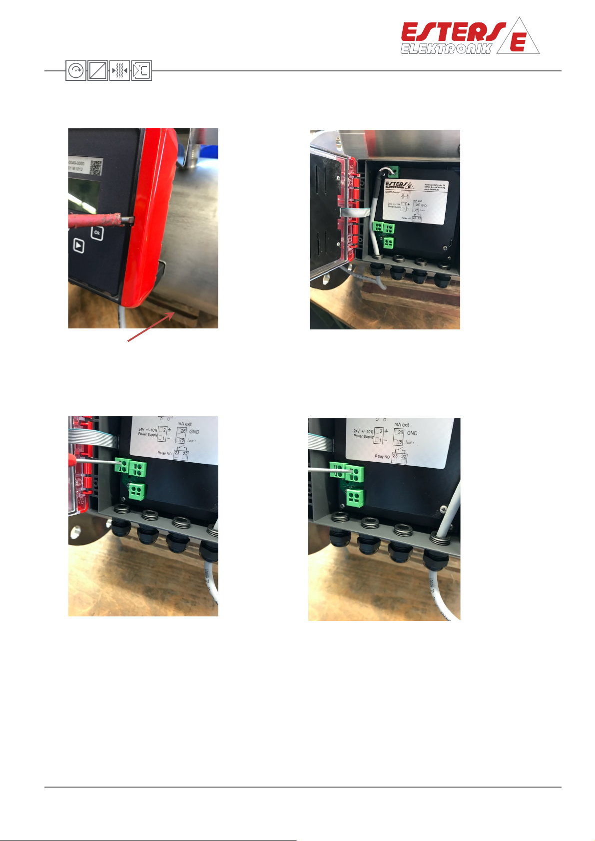
2.4 Connecting of the GDR 150x
Step 4.1: open the lid of the GDR 150x on the
right side using a small screwdriver
A connection diagram is available inside the
device.
Step 4.2: Sensor
- Open a cable gland
- Insert the 2-wire cable of the sensor
- Connect the wire to terminal 8 and 9
- Close the cable gland
Step 4.3: Power supply
- Open a cable gland
- Insert the cable of the 24 V DC power supply
- Connect the wire to terminal 1 (-) and 2 (+)
- Close the cable gland
Step 4.4: Output: mA and relay
- Open a cable gland for each output signal
- Insert the 3-wire cable for the mA signal output
- Connect the wire to terminal 24 (pulse), 25 (Iout)
and 26 (GND)
- Insert the 2-wire cable for the relay NO output
- Connect the wire to terminal 22, 23
- Close the cable glands
Table of contents
Other ESTERS ELEKTRONIK Desktop manuals


