Crystal Mountain Storm User manual


Table of Contents
SECTION1:Product Specification ................................................................................................................. 1-1
SECTION2:Parts Listing and Exploded Views......................................................................... ....................... 2-1
Storm Parts Listing ................................................................................................................................. 2-1
Exploded Views ..................................................................................................................................... 2-2
Product Dimensions ............................................................................................................................... 2-5
Description of Product Model Number ...................................................................................................... 2-6
SECTION3: Replacement of SmartFlo Water Cartridge ...........................................................................................................3-1
SECTION4: Water Bottle Install & Replacement ............................................................................................. 4-1
SECTION5: Electrical Component Diagnosis and Replacement....................................................................... 5-1
Wiring and Schematics ........................................................................................................................... 5-1
Cold Thermostat Remove and Installation ................................................................................................ 5-2
Cold Thermostat Adjustment ................................................................................................................... 5-4
Hot Tank Auto Cutout / Manual Reset Replacement .................................................................................. 5-5
Hot Tank Removal and Replacement ....................................................................................................... 5-6
Compressor Relay / Overload Protector Replacement ............................................................................. 5-9
SECTION6:Trouble Shooting ....................................................................................................................... 6-1
SECTION7:Cleaning & Sanitization ............................................................................................................. 7-1

ITEM
POWER RATING
STANDARD CURRENT
POWER
CONSUMPTION
COLD
HOT
NOISE(SOUND POWER LEVEL)
NET WEIGHT
LOADING QUANTITY
COLD
HOT
COMPRESSOR
REFRIGERANT
TEMP RANGE
HEATER
TEMP RANGE
SAFETY DEVICE
TEMP CONTROL
SPECIFICATIONS
SINGLE PHASE
100-115VAC 60Hz
Hot & Cold: 4.8~5.3A
70W
500W
SINGLE PHASE MOTOR
R134a
4-10°C (39.2-50°F)
INTERNAL HEATER
76°C -92°C (168.8°F -197.6°F)
BIMETAL (AUTO RESET 93°C (199.4°F) OFF)
BIMETAL 85°C (185°F)
Pump: 55dB(A); Compressor: 43dB(A)
Hot & Cold: 14.5kg (32.0 Ib)
20FT: 204UNITS
40FT: 420UNITS
Cooler Specifications
Our new Bottom-Load water dispenser is the latest model in
Crystal Mountain’s line of coolers. The Bottom-Load means
no more lifting heavy bottles, just open the front door and
the bottle slides into the base of the cooler with little effort.
The Storm features an easy to remove reservoir system, that
takes less than a minute to change. The LED indicator tells
you when it needs to be replaced. Servicing has never been
easier. With its contemporary design, attractive finish, con-
cealed faucets and easy maintenance, the Storm is sure to
dazzle in any environment.
Product Specification
STORM (Bottom-Load)
Crystal Mountain Products Limited
North American Ofce (Sales & Service)
11925 -145th Street Edmonton, Alberta Canada T5L 2H4
Crystal Mountain Products Inc.
US Ofce / Warehouse
915 Taylor Rd, Unit 3 Gahanna OH 43230

115V Storm Bottled Water Cooler Parts Listing MODEL--STFM2KHK1C
NO. PART CODE NO. PART CODE
1 PLC-C150002 C9
DOOR RAIL CAP PLC-C150033
2 ELE-C100197 C10
L SHAPE HINGE PIN, 3MM X 34MM FAS-C100113
3 ELE-C100208 C11
12VDC MOTOR, 1600 RPM ELE-C100204
4 PLC-C150028 C12
MOTOR BUSHING PLC-C150052
5 FAS-C100109 C13
PCB, CONTROL BOARD ELE-C100205
6 PLC-C150027 C14
NEW STEAM VALVE ASSEMBLY-ST SUB-C200414
7 PLC-C150038 C15
PINCH TUBE, HOT - 7MM X 172MM SIL-C150004
8 PLC-C150055
9 SUB-C200277
10 PLC-C150012 115V HOT TANK + ELECTRICAL ASSEMBLY(INTERNAL 500W)
SUB-C200230
11 PLC-C150111 D1
SEAL, MANIFOLD INLET/OUTLET - OD18 X 11MM SIL-C120006
12 PLC-C150054 D2
98C CERAMIC MANUAL RESET ELE-C100170
13 ELE-C000010 D3
85C AUTO RESET, SEALED - TB ELE-C100275
14 PLC-C150004 D4
HOT DRAIN TUBE - 8MM X 280MM SIL-C150002
D5
SPRING CLIP - 12MM FAS-C000029
TOP COVER ASSM, BLACK/CHROME - BLC SUB-C200232 D6
HOT TANK DRAIN - SUBLIM'O PLC-C120021
A1 TOP COVER TRIM, CHROME PLC-C150014 D7
HT DRAIN CAP + SEAL SUB-C000182
A2 TOP COVER, BLACK PLC-C150005
A3 TOP COVER CATCH PLC-C150025 115V REFRIGERATION SYSTEM REPLACEMENT PARTS N/A
E1
WP4V COLD THERMOSTAT REF-C100035
B2 BOTTLE ADAPTOR ASSEMBLY SUB-C200235 E2
115V COMPRESSOR RELAY - B25H5 REF-C100168
E3
115V HUAYI COMP PROTECTOR - B25H5 REF-C100167
UPPER SHELF ASSEMBLY
SUB-C200228 E4 COVER, HUAYI B25H5 REF-C100164
C1
LATCH, WATER OUTLET PLC-C150031
C2
NEW COLD FAUCET LEVER ASSY.(BLUE) SUB-C200447 DOOR ASSEMBLY SUB-C200233
C3
NEW HOT FAUCET LEVER ASSY.(RED) SUB-C200445 F1 DOOR HANDLE, CHROME PLC-C150015
C4
HOT FAUCET LEVER(RED) SUB-C200275 F2 DOOR SLIDER-LH, BLACK PLC-C150010
C5
PCB, SWITCH BOARD ELE-C100207 F3 DOOR SLIDER-RH, BLACK PLC-C150009
C6
HINGE PIN, TOP COVER - EV FAS-C100091 F4 DOOR WINDOW, BLACK PLC-C150016
C7
PCB, LED INDICATOR ELE-C100206
C8
SAFETY BUTTON, RED PLC-C150056 BASE PLATE ASSEMBLY SUB-C200225
G1 BOTTLE LOW INDICATOR, BLACK PLC-C150041
20PCS SmartFlo™ IN ONE BULK BOX SUB-C200343 G2 PCB, BOTTLE LOW INDICATOR ELE-C100209
9PCS SmartFlo™ IN ONE BULK BOX SUB-C200344 G3 BASE PLATE, BLACK PLC-C150001
06-03-2018
C
D
DESCRIPTION
DESCRIPTION
BACK PANEL, BLACK
115V POWER CORD, BLACK 45
TRANSFORMER, 115VAC TO 15VDC
DOOR SPRING HOLDER
SPRING BLOCK
G
SS SPRING, DOOR
HOT TANK POWER SWITCH
C
A
DOOR RAIL, 1015MM
LED LIGHT TUBE - ST
H&C FACE PLATE, BLACK+ PRINTING (WHITE)
CLIP, BOTTLE ADAPTOR
F
DRIP TRAY COVER, BLACK
DRIP TRAY BASE, DEEP VERSION, BLACK
E
FRONT PANEL, BLACK - ST


Product Dimensions
Storm (Bottom-Load)
2 - 5
2 - 6
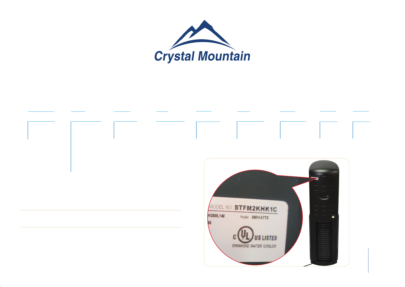
You can find your serial and model number at the back of your cooler.
ST F M 2 K H K 1 C
Cooler Shape Reservoir Type Type of Lid No. of Faucets Body Color Temp. Option Insert Color Voltage Option
Description of Product Model Number
ST – Storm
F– SmartFlo SF-1 Water Cartridge
M –Manifold K – Black H – Hot & Cold K – Black 1 – 110~115V C – Made in China

3 - 1
Replacement of SmartFlo™ Water Cartridge
For the best tasting and highest quality water, it is recommended to change the SmartFlo™ Water Car-
tridge every 12 months. Follow the steps below to replace the SmartFlo™ Water Cartridge. It is recom-
mended to empty the bottle prior to replacement of the SmartFlo™ Water Cartridge and bottle adaptor.
Note: A flashing blue light above the cold water lever will alert you to when the SmartFlo™ Water Car-
tridge should be replaced. The system has been pre-set to provide indication after a period of 12 months
of use. User may operate the cooler as normal until the bottle has been emptied.
Note: To reset the life timer system, the SmartFlo™ is required to be removed from the dispenser for a
minimum of 15 seconds while the unit is connected to the mains power supply.
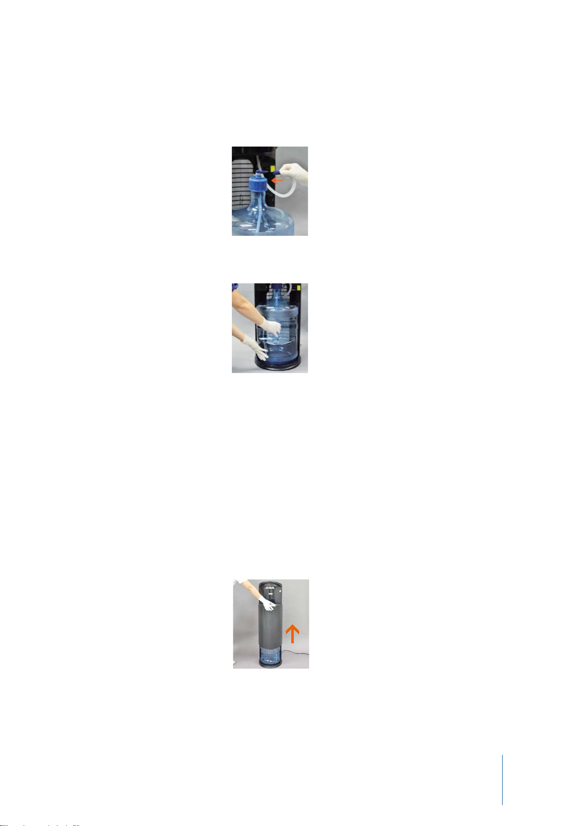
1. Open Dispenser door (Figure 3-1). (Slide door upwards to allow access to bottle area)
2. Slide empty bottle out of cabinet (Figure 3-2 and Figure 3-3).
3. Disconnect the water line from the bottle adaptor (Figure 3-4).
4. Open the replacement SmartFlo™ Water Cartridge kit, and remove the access key provided.
Notice:
The information and/or procedures presented in the following demonstration(s) should be performed by a trained Water
Cooler Service Technician only.
Prior to any service or repair of the water cooler, ensure that the water has been completely drained from the system.
Figure 3-1
Figure 3-4
Figure 3-2 Figure 3-3

3 - 2
5. Insert the access key into the 2 holes located at the underside of the top edge of the cooler (above
water levers) and push inwards (Figure 3-5 and Figure 3-6)(once unlocked, the front of the top cov-
er opens upwards).
6. Place a glass or other container below the water outlets (to catch drips), and unlatch the locking
clip located near the front of the cooler to release the water tubing (Figure 3-7).
7. Unlock the turn knobs which hold down the SmartFlo™ Water Cartridge (Figure 3-8).
8. Pull SmartFlo™ Water Cartridge upwards to remove (Figure 3-9).
9. Discard used SmartFlo™ Water Cartridge according to local regulations. (Whenever possible,
please recycle).
Figure 3-5 Figure 3-6
Figure 3-7
Figure 3-8
Figure 3-9

3 - 3
10. Insert water line of replacement SmartFlo™ Water Cartridge through the guide tube, and push
through to bottle installation area (Figure 3-10).
11. Ensure gasket/seal is properly installed on the outlet tube of the SmartFlo™ Water Cartridge as-
sembly (may have shifted during shipment or un-packaging) (Figure 3-11).
12. Align SmartFlo™ Water Cartridge with openings in cooler, and push into place (Figure 3-12 and
Figure 3-13).
13. Rotate turn knobs to lock SmartFlo™ Water Cartridge in place (Figure 3-14).
14. Close the locking clip to secure water outlet tubing in place (Figure 3-15).
15. Close the top cover of the cooler (Figure 3-16) (push downwards to lock into place).
Figure 3-10
Figure 3-11 Figure 3-12 Figure 3-13 Figure 3-14
Figure 3-15
Figure 3-16

3 - 4
16. Place fresh bottle outside of the cabinet.
17. Clean the outside of new bottle with a cloth (Figure 3-17). Remove security label/seal from the
bottle cap (if applicable).
18. Remove bottle adaptor assembly from the empty bottle, and set aside (Figure 3-18) .Carefully
un-package the Bottle Adaptor assembly (located in the bottle storage area), avoiding touching the
tube.
Note: to maintain sanitization of the system, refrain from touching the section of the bottle adaptor
tube that is inserted into the bottle.
19. Without touching the tube, install the Spike Cap (with the end of the tube in the Spike Cap) (Figure
3-19 and Figure 3-20 )
20. Push the tube to go through the Spike Cap, until it is close/hits bottom of the bottle (Figure 3-21)
Figure 3-19 Figure 3-20
Figure 3-17
Figure 3-18
Figure 3-21

3 - 5
21. Remove red protective cap from the blue tube of the Smartflo™ Water Cartridge and install onto
the bottle adaptor assembly (Figure 3-22).
22. Slide bottle into cabinet and close the door (Figure 3-23 to Figure 3-24) (slide door downwards to
close)
23. Depress the Cold or Hot water lever to fill the respective tanks (Figure 3-25 and Figure 3-26).
When water begins to flow from both faucets, the tanks have been filled (approximately 1 minute per
tank although it may be less time).
Figure 3-23 Figure 3-24
Figure 3-25 Figure 3-26
Figure 3-22

4 - 1
Install and Change Water Bottle
Install Water Bottle
1. Open Dispenser door (Figure 4-1). (slide door upwards to allow access to bottle area).
2. Place fresh bottle outside of the cabinet.
3. Clean the outside of new bottle with a cloth (Figure 4-2).
4. Remove security label/seal from the bottle cap (if applicable) and install Spike Cap through the bottle
cap (do not remove Bottle Cap) and press down to secure (Figure 4-3 and Figure 4-4).
5. Insert the Bottle adaptor assembly through Spike cap until tube hits bottom of the bottle (Figure 4-5
and Figure 4-6).
Figure 4-1
Figure 4-2
Figure 4-3 Figure 4-4
Figure 4-5 Figure 4-6
4 - 2
6. Remove the red protective cap from the blue tube of SmartFlo™ Water Cartridge and install
onto the bottle adaptor assembly (Figure 4-7).
7. Slide bottle into cabinet (Figure 4-8) and close the door (slide door downwards to close).
Bottle Change
A flashing red light above the cold water lever will alert you when your water bottle is getting low.
The bottle will need to be replaced shortly. Water may be dispensed normally until empty (no wa-
ter flows from water outlet when levers are depressed).
1. Open Dispenser door (Figure 4-9). (Slide door upwards to allow access to bottle area).
Figure 4-7
Figure 4-8
Figure 4-9

4 - 3
2. Slide empty bottle out of cabinet (Figure 4-10).
3. Place fresh bottle outside of the cabinet.
4. Clean the outside of new bottle with a cloth (Figure 4-11). Remove security label/seal from the
bottle cap (if applicable).
5. Remove bottle adaptor and Spike Cap from the empty bottle (Figure 4-12) and remove the cap
from the Hose Assembly (Figure 4-13).
Note: to maintain sanitization of the system, refrain from touching the section of the bottle adaptor
tube that is inserted into the bottle.
6. Install Spike Cap through the bottle cap (do not remove Bottle Cap) and press down to secure
(Figure 4-14 and Figure 4-15).
Figure 4-10
Figure 4-11
Figure 4-12 Figure 4-13
Figure 4-14 Figure 4-15

4 - 4
7. Insert the Bottle adaptor assembly through Spike cap until tube hits bottom of the bottle (Figure
4-16 and Figure 4-17).
8. Slide bottle into cabinet and close the door (Figure 4-18 to Figure 4-20) (slide door downwards
to close).
9. Place a container under faucet and dispense cold water until a smooth stream of water is dis-
pensed (may take up to 1 minute).
Figure 4-16 Figure 4-17
Figure 4-18 Figure 4-19 Figure 4-20

Wiring and Schematics Models: Storm Hot & Cold water cooler
SECTION 5 Electrical Component Diagnosis and Replacement
5-1
Limiter Hot Thermostat
Limiter
Hot Thermostat
5 - 2
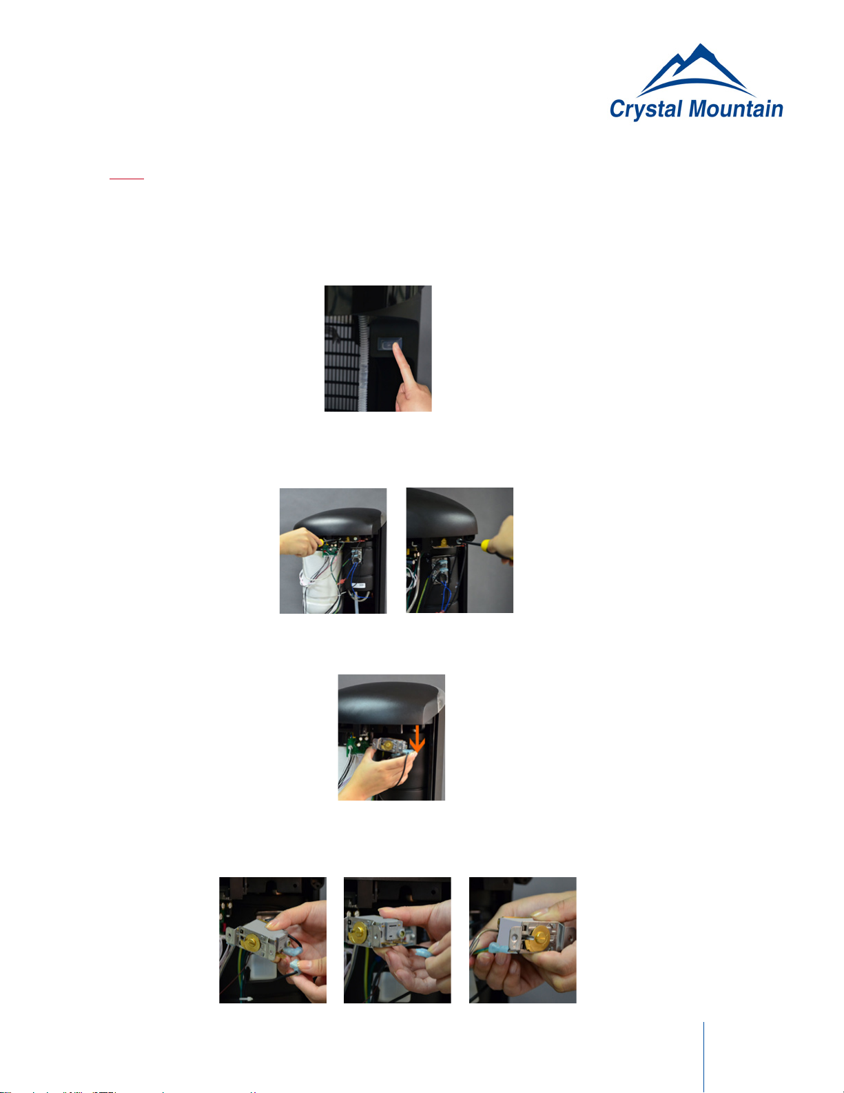
1. Turn off hot tank power switch (located on the front panel and behind the door) (Figure 5-2-1) and
unplug the water cooler.
2. Remove the back panels from the water cooler.
3. Remove the 2 mounting screws from the cold thermostat (Figure 5-2-2 and Figure 5-2-3).
4. Remove cold thermostat from the plastic shelf (Figure 5-2-4).
5. Remove the terminals from the thermostat, taking care to identify where which terminals are in-
stalled (Figure 5-2-5, Figure 5-2-6 and Figure 5-2-7).
Cold Thermostat Removal and Installation
Figure 5-2-1
Figure 5-2-2 Figure 5-2-3
Figure 5-2-5 Figure 5-2-6 Figure 5-2-7
Figure 5-2-4
Notice:
The information and/or procedures presented in the following demonstration(s) should be performed by a trained Water
Cooler Service Technician only.
Never attempt to service or repair a water cooler while it is plugged into any power supply.
Prior to any service or repair of the water cooler, ensure that the water has been completely drained from the system.

5 - 3
6. Cut the small plastic tie strap (holding cold thermostat sensor to evaporator insulation)(Figure 5-2-8).
7. Pull the sensor tube out from the Evaporator Insulation to remove (Figure 5-2-9).
Note: If required, install the Sensor tube cover onto the replacement cold thermostat.
8. Install the replacement cold thermostat into the evaporator insulation (insertion length approxi-
mately 5 inches/125mm) (Figure 5-2-10).
Note: Care should be taken while installing the sensor tube that the protective cover within the evapo-
rator insulation is in the proper position.
9. Install a replacement plastic tie to hold the sensor within the evaporator insulation.
10. Reinstall the wire terminals onto the Cold Thermostat (take care to ensure proper installation loca-
tion).
11. Reinstall screws on the cold thermostat to the plastic shelf.
12. Reinstall back panel. Plug the cooler and switch on.
Note: Ensure proper thermostat setting (see section for Cold Thermostat setting).
Figure 5-2-8
Figure 5-2-9
Figure 5-2-10
Other manuals for Storm
2
Table of contents
Popular Accessories manuals by other brands

PCB Piezotronics
PCB Piezotronics 123B21 Installation and operating manual

Linkit
Linkit LKS400 Series Operator's manual

PumpSpy
PumpSpy Sump Pump Smart Outlet Setup instructions

ELRO
ELRO HE821S quick start guide

Baumer
Baumer OADR 20I6565/S14F quick start guide

VOLTCRAFT
VOLTCRAFT VC-SL16000 operating instructions


