manuals.online logo
Brands
  1. Home
  2. •
  3. Brands
  4. •
  5. Festo
  6. •
  7. Accessories
  8. •
  9. Festo Sensorbox SRBG-C1-N-20N-ZC-M12-EX5 Instruction manual

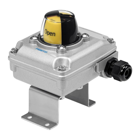
Festo Sensorbox SRBG-C1-N-20N-ZC-M12-EX5 Instruction manual

Translation of the original instructions
1 Identification EX
Type Identification ATEX Certificates
II 1G Ex ia IIC T6…T1 GaSRBG-C1-N-20N-ZC-M12-EX5
II 1D Ex ia IIIC T135°C Da
SRBG-C1-N-20N-ZC-C2-C2-EX5 II 1G Ex ia IIC T6…T1 Ga
TÜV 16 ATEX 174269X
Tab. 1
Type Identification IECEx Certificates
Ex ia IIC T6…T1 GaSRBG-C1-N-20N-ZC-M12-EX5
Ex ia IIIC T135°C Da
SRBG-C1-N-20N-ZC-C2-C2-EX5 Ex ia IIC T6…T1 Ga
IECEx TUN 18.0003X
Tab. 2
2 Further applicable documents
User documentation
Sensorbox, SRBG Instructions Operating
Tab. 3
All available documents for the product èwww.festo.com/pk.
3 Safety
3.1 Safety instructions
– The sensor box SRBG-C1-N-20N-ZC-M12-EX5 can be used in zone 0 of poten-
tially explosive gas atmospheres and in zone 20 of potentially explosive dust
atmospheres.
– The sensor box SRBG-C1-N-20N-ZC-C2-C2-EX5 can be used in zone 0 of poten-
tially explosive gas atmospheres.
– Carry out all work outside potentially explosive areas.
3.2 Intended use
Inductive dual sensors are intended for recording and display of the position of
process valves.
3.3 Identification X: Special conditions
– Ambient temperatureè 9 Technical data.
– Refer to the relevant certificate to see the relationship between the connected
circuit type, the maximum permitted ambient temperature, the effective inner
reactances, and if applicable the surface temperature or the temperature
class.
– Protect the device from impact effects if it is used in the temperature range
between the minimum permissible ambient temperature and -20 °C.
– Avoid electrostatic charges which could result in electrostatic discharges
while installing, operating, or maintaining the device.
– Avoid in admissibly high electrostatic charge of the metal housing compon-
ents on the device. Include the metal housing components in the equipoten-
tial bonding.
– Protect cables and cable glands from tensile load and torsional stress or use
certified cable glands.
– The sensor circuits for SRBG-C1-N-20N-ZC-M12-EX5 have to be considered
galvanically connected to each other, in safety technical point of view for
Group III. Verification of intrinsic safety must include the possibility of the
interconnection of these intrinsically safe circuits. The functional galvanically
separation remains unaffected.
– Mount the device with at least a degree of protection of IP20 according to
IEC/EN 60529.
– Mount the device in such a way that the bare casting resin surface is not
exposed to mechanical hazards.
4 Installation
NOTICE!
During commissioning, maintenance and installation of the sensor, make sure
that the regulations in accordance with EN 60079-14 and EN 60079-25 are com-
plied with.
NOTICE!
Installation and commissioning may only be performed in accordance with the
operating instructions and by qualified personnel.
WARNING!
The discharge of electrostatically charged parts can lead to sparks which can
cause an explosion. Prevent electrostatic discharges by means of suitable install-
ation and cleaning measures.
5 Electrical connection
NOTICE!
Electrical specifications and operating conditions in accordance with the product
label.
Connection is dependent on the sensor box.
– SRBG-C1-N-20N-ZC-C2-C2-EX5: Terminal box with spring-loaded terminal
– SRBG-C1-N-20N-ZC-M12-EX5: M12x1 plug connector
WARNING!
Avoid ignition of explosive atmosphere.
For SRBG-C1-N-20N-ZC-C2-C2-EX5:
• Tighten cover firmly.
– Tightening torque: 1Nm
SRBG-C1-N-20N-ZC-C2-C2-EX5
Fig. 1
NOTICE!
If the polarity of the solenoid valve circuit connections are reversed, the valve
status indicator will not function. Low energy valves can thus be connected.
SRBG-C1-N-20N-ZC-M12-EX5
Fig. 2
6 Operation
If the equipment is not used under atmospheric conditions, a reduction of the per-
missible minimum ignition energy must be taken into consideration.
NOTICE!
The intrinsic safety is only assured in connection with corresponding equipment
and according to the proof of intrinsic safety.
– Cable connectors and blanking plugs must be approved for use in explosion
protection areas.
8079486
SRBG-C1-N-20N-ZC-…-EX5
Sensorbox
8079486
2017-10a
[8079488]
Operating conditions|EX
Festo AG & Co. KG
Ruiter Straße 82
73734 Esslingen
Germany
+49 711 347-0
www.festo.com
7 Maintenance and care
The device is maintenance-free.
– Clean the device with a damp cloth only. Do not use the following agents:
– scouring agents
– alcohol
– solvents
– Protect surfaces from excessive temperature rise.
8 Fault clearance
Fault description Cause Remedy
Incorrect or unexpected signal Wire break Replace cable
Tab. 4
9 Technical data
Operating conditions
Storage temperature [°C] -40…100
Ambient temperature Tmin [°C] -25
Effective internal inductance Li for sensor circuit's
with cable length £ 10 m [μH] 100
Effective internal capacity Ci for sensor circuit's
with cable length £ 10 m [nF] 100
Valve circuit for SRBG-C1-N-20N-ZC-C2-C2-EX5
Effective internal inductanceLi
with cable length £ 10 m
[μH] 20
Effective internal capacity Ci
with cable length £ 10 m
[nF] 10
Valve circuit Ui = 32 V
Ii = 240 mA
Electrical connection
SRBG-C1-N-20N-ZC-M12-EX5 M12 x 1 , plug connector, 4-pin
High-alloy stainless steel
SRBG-C1-N-20N-ZC-C2-C2-EX5 Terminal box with spring-loaded terminal
Nominal conductor cross section that can be connected
SRBG-C1-N-20N-ZC-C2-C2-EX5 [mm2] flexible: 0.2…1.5
rigid: 0.2…2.5
Cable connector
SRBG-C1-N-20N-ZC-C2-C2-EX5 M20 x 1.5 (sensor)
M12 x 1.5 (valve)
Operating voltage range [V DC] 8.2
Max. switching frequency [Hz] 3000
Protection against short circuit yes
Protection against incorrect polarity for all electrical connections
Switching element function normally closed contact
Current consumption
Calibrating plate not recorded [mA] ³3
Calibrating plate recorded [mA] £1
Protection class IP67 in accordance with EN 60529
Switching output NAMUR in accordance with DIN EN 60947-5-6
Measuring principle inductive
Mounting dimensions corresponding to VDI/VDE 3845
Materials
Housing PBT
Screws High-alloy stainless steel
Tab. 5
ATEX operating conditions
Ambient temperature Tmax SRBG-C1-N-20N-ZC-M12-EX5
Ui: 15 V
Ii: 25 mA
Pi: 34 mW
T6: 55 °C
T5: 70 °C
T4…T1: 95 °C
Group IIIC: 100 °C
Ui: 15 V
Ii: 25 mA
Pi: 64 mW
T6: 55 °C
T5: 70 °C
T4…T1: 95 °C
Group IIIC: 100 °C
Ui: 15 V
Ii: 52 mA
Pi: 169 mW
T6: 50 °C
T5: 60 °C
T4…T1: 90 °C
Group IIIC: 90 °C
Ambient temperature Tmax SRBG-C1-N-20N-ZC-C2-C2-EX5
Ui: 15 V
Ii: 25 mA
Pi: 34 mW
T6: 55 °C
T5: 65 °C
T4…T1: 95 °C
Ui: 15 V
Ii: 25 mA
Pi: 64 mW
T6: 55 °C
T5: 65 °C
T4…T1: 95 °C
Ui: 15 V
Ii: 52 mA
Pi: 169 mW
T6: 45 °C
T5: 60 °C
T4…T1: 85 °C
Tab. 6
IECEx operating conditions
Ambient temperature Tmax SRBG-C1-N-20N-ZC-M12-EX5
Ui: 15 V
Ii: 25 mA
Pi: 34 mW
T6: 75 °C
T5: 90 °C
T4…T1: 100 °C
Group IIIC: 100 °C
Ui: 15 V
Ii: 25 mA
Pi: 64 mW
T6: 75 °C
T5: 90 °C
T4…T1: 100 °C
Group IIIC: 100 °C
Ui: 15 V
Ii: 52 mA
Pi: 169 mW
T6: 65 °C
T5: 80 °C
T4…T1: 90 °C
Group IIIC: 90 °C
Ambient temperature Tmax SRBG-C1-N-20N-ZC-C2-C2-EX5
Ui: 15 V
Ii: 25 mA
Pi: 34 mW
T6: 70 °C
T5: 85 °C
T4…T1: 100 °C
Ui: 15 V
Ii: 25 mA
Pi: 64 mW
T6: 70 °C
T5: 85 °C
T4…T1: 100 °C
Ui: 15 V
Ii: 52 mA
Pi: 169 mW
T6: 65°C
T5: 80 °C
T4…T1: 90 °C
Tab. 7
10 Approved accessories
Designation Type Part no.
Position indicator SASF-S2-B-F-A34 4046082
Position indicator SASF-S2-B-F-A56 4077125
Tab. 8

This manual suits for next models

1

Other Festo Accessories manuals

Festo SDE5 series User manual

Festo

Festo SDE5 series User manual

Festo VN Series User manual

Festo

Festo VN Series User manual

Festo SRAP-M-CA1 Series User manual

Festo

Festo SRAP-M-CA1 Series User manual

Festo Span Series User manual

Festo

Festo Span Series User manual

Festo MS6-SFE-F5-AGD Series User manual

Festo

Festo MS6-SFE-F5-AGD Series User manual

Festo SDE1 Series User manual

Festo

Festo SDE1 Series User manual

Festo SMPO-I -H-B User manual

Festo

Festo SMPO-I -H-B User manual

Festo ASLR-D-L1 User manual

Festo

Festo ASLR-D-L1 User manual

Festo SDAT-MHS User manual

Festo

Festo SDAT-MHS User manual

Festo SPAU User manual

Festo

Festo SPAU User manual

Festo SBSI-EN Service manual

Festo

Festo SBSI-EN Service manual

Festo SFAM-62-***-T User manual

Festo

Festo SFAM-62-***-T User manual

Festo PEV-1/4A Series User manual

Festo

Festo PEV-1/4A Series User manual

Festo SFAW User manual

Festo

Festo SFAW User manual

Festo VMPA-FB-PS Series User manual

Festo

Festo VMPA-FB-PS Series User manual

Festo SFAB User manual

Festo

Festo SFAB User manual

Festo SFAB Parts list manual

Festo

Festo SFAB Parts list manual

Festo SOPA Series User manual

Festo

Festo SOPA Series User manual

Festo SPAE User manual

Festo

Festo SPAE User manual

Festo CP Lab User manual

Festo

Festo CP Lab User manual

Festo SPAW series User manual

Festo

Festo SPAW series User manual

Festo SFAB-PNLK Series User manual

Festo

Festo SFAB-PNLK Series User manual

Festo SFAH Parts list manual

Festo

Festo SFAH Parts list manual

Festo SFAH Operating and installation instructions

Festo

Festo SFAH Operating and installation instructions

Popular Accessories manuals by other brands

Sunx DP2-20 instruction manual

Sunx

Sunx DP2-20 instruction manual

Young Living Feather the Owl Operation manual

Young Living

Young Living Feather the Owl Operation manual

TeraBee TeraRanger Multiflex Installation and operation manual

TeraBee

TeraBee TeraRanger Multiflex Installation and operation manual

Seifert SlimLine Pro KG 8540 instruction manual

Seifert

Seifert SlimLine Pro KG 8540 instruction manual

RBIT iBill user manual

RBIT

RBIT iBill user manual

Celestron 94155 instruction manual

Celestron

Celestron 94155 instruction manual

Panasonic MA4X713 (MA713) Specification sheet

Panasonic

Panasonic MA4X713 (MA713) Specification sheet

Panasonic MQ-W EM Series instruction manual

Panasonic

Panasonic MQ-W EM Series instruction manual

Netview Technologies VUEBELL quick start guide

Netview Technologies

Netview Technologies VUEBELL quick start guide

Sharp User Authentication Operation manual

Sharp

Sharp User Authentication Operation manual

Seen IRIS 860 Sensor Quick install guide

Seen

Seen IRIS 860 Sensor Quick install guide

JOCCA 3332 instruction manual

JOCCA

JOCCA 3332 instruction manual

Panasonic KX-HNS104 installation guide

Panasonic

Panasonic KX-HNS104 installation guide

Di-soric UGUTI 6/70 G6-RB5 manual

Di-soric

Di-soric UGUTI 6/70 G6-RB5 manual

DURAVANT FMH NestaFlex Gravity 376PL Operator's manual

DURAVANT

DURAVANT FMH NestaFlex Gravity 376PL Operator's manual

Sound Devices USBPre 2 User guide and technical information

Sound Devices

Sound Devices USBPre 2 User guide and technical information

Me inertialSENSOR ACC5703 operating instructions

Me

Me inertialSENSOR ACC5703 operating instructions

Lightolier Compact Fluorescent Frame-In Kit instructions

Lightolier

Lightolier Compact Fluorescent Frame-In Kit instructions

manuals.online logo
manuals.online logoBrands
  • About & Mission
  • Contact us
  • Privacy Policy
  • Terms and Conditions

Copyright 2025 Manuals.Online. All Rights Reserved.