manuals.online logo
Brands
  1. Home
  2. •
  3. Brands
  4. •
  5. Baumer
  6. •
  7. Accessories
  8. •
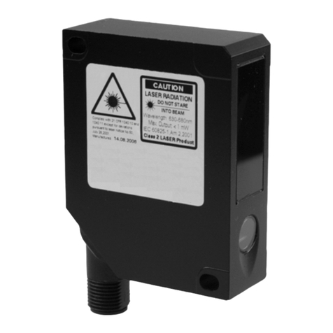
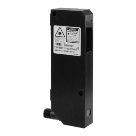
  9. Baumer OADR 20I6565/S14F User manual

Baumer OADR 20I6565/S14F User manual

11040828
Í?+$(<ÂÂ*Â*Î
1/4
Canada
Baumer Inc.
CA-Burlington, ON L7M 4B9
Phone +1 (1)905 335-8444
China
Baumer (China) Co., Ltd.
CN-201612 Shanghai
Phone +86 (0)21 6768 7095
Denmark
Baumer A/S
DK-8210 Aarhus V
Phone +45 (0)8931 7611
France
Baumer SAS
FR-74250 Fillinges
Phone +33 (0)450 392 466
Germany
Baumer GmbH
DE-61169 Friedberg
Phone +49 (0)6031 60 07 0
India
Baumer India Private Limited
IN-411038 Pune
Phone +91 20 2528 6833/34
Italy
Baumer Italia S.r.l.
IT-20090 Assago, MI
Phone +39 (0)2 45 70 60 65
Singapore
Baumer (Singapore) Pte. Ltd.
SG-339412 Singapore
Phone +65 6396 4131
Sweden
Baumer A/S
SE-56133 Huskvarna
Phone +46 (0)36 13 94 30
Switzerland
Baumer Electric AG
CH-8501 Frauenfeld
Phone +41 (0)52 728 1313
United Kingdom
Baumer Ltd.
GB-Watchfield, Swindon, SN6 8TZ
Phone +44 (0)1793 783 839
USA
Baumer Ltd.
US-Southington, CT 06489
Phone +1 (1)860 621-2121
www.baumer.com/worldwide
Baumer Electric AG · CH-8501 Frauenfeld
Phone +41 (0)52 728 1122 · Fax +41 (0)52 728 1144
IND. CONT. EQ
1DD2
< 100 mA
OADR 20I6565/S14F
30...130 mm
> 3 mm
0.005...0.06 mm
±0.015... ±0.2 mm
20,25 51
7,539,5
65
*6
1
1xM 21
16,4
LED
457
4,6
9
U
analog 4...20 mA (3)
+Vs (2)
teach in (4)
alarm (5)
n.c. (1)
sync in (8)
0V (7)
analog 0...10 V (6)
● = elektrische Verbindung/electrical connection/connexion électrique
Power-supply
A/D Converter
OADM
4...20 mA / 0...10 VDC
Stromaufnahme max. (ohne Last) current consumption max. (no load) Consommation max. (sans charge)
IP 69K
2/4
RED LED ON
Runde, glänzende Oberächen
Round glossy surfaces
Surfaces ronds brillantes
Glänzende Oberächen
Glossy surfaces
Surfaces brillantes
Gradins
Stufen
Steps
Einwirkung Fremdlicht
Eect of ambient light
Inuence lumiére ambiante
Surfaces dieremment rééchissantes
Unterschiedlich reektierende Oberächen
Dierent reection of surfaces
Allg. Sicherheitsbestimmungen
General safety instructions
Instructions générales de sécurité
Montage Mounting Montage
Hinweis zur Elektromagnetischen Verträglichkeit:
Sensor geerdet montieren und geschirmtes
Anschlusskabel verwenden.
Note to electromagnetic compatibility:
Connect the sensor housing to earth potential.
Use shielded connecting cables.
Note à la compatibilité électromagnétique:
Connecter le boîtier du détecteur au potentiel de terre.
Utiliser des câbles de raccordement blindés.
•Aus Lasersicherheitsgründen muss die Spannungsversorgung dieses Sensors abgeschaltet werden, wenn die ganze Anlage oder Maschine
abgeschaltet wird.
•Laser regulations require the power of the sensor to be switched o when turning o the whole system this sensor is part of.
•Pour des raisons de sécurité, l'alimentation de ce détecteur laser doit être coupée en cas d'arrêt total du système incorporan t ce détecteur.
Laserstrahl nie auf ein Auge richten.
Es empfiehlt sich, den Strahl nicht ins Leere
laufen zu lassen, sondern mit einem matten
Blech oder Gegenstand zu stoppen.
Do not point the laser beam towards
someone's eye. It is recommended to
stop the beam by a mat object or mat
metal sheet.
Ne dirigez jamais le faisceau vers un oeil.
Il est conseillé de ne pas laisser le faisceau
se propager librement mais de l'arrêter au
moyen d'un objet de surface mate.
VORSICHT CAUTION ATTENTION
LASER RADIATION
DO NOT STARE INTO BEAM
Wavelength: 640...670nm
IEC 60825-1, Ed. 3, 2014
CLASS 2 LASER PRODUCT
Complies with 21 CFR 1040.10 and 1040.11
except for conformance with IEC 60825-1 Ed. 3.,
as described in Laser Notice No. 56, dated May 8, 2019
3/4
OADR 20I6565/S14F
30 mm 130 mm
0 V
4 mA
10 V
20 mA
30 mm 130 mm
Jeder Sensor wird mit dem im Datenblatt angegebenen Messbereich ausgeliefert. Das Teachen
dient dazu, den Messbereich auf kleinere Grenzen einzustellen und so die Auflösung und Linearität
zu optimieren. Der Strom-, resp. der Spannungsausgang erhält dadurch eine neue Kennlinie. Es
werden immer 2 Abstände geteacht.
• Der erste Abstand entspricht 0 V bzw. 4 mA, der zweite Abstand entspricht 10 V bzw. 20 mA.
• Die geteachten Punkte bestimmen den Anfang und das Ende des neuen Messbereiches (liegen
somit innerhalb des Messbereiches).
• Der Sensor kann mindestens 10'000 mal geteacht werden.
• Der Fabrikzustand kann jederzeit wieder hergestellt werden.
• Der Sensor kann über die Leitung geteacht werden.
• Beim Teachen wird die rote LED für das Teach-Feedback benutzt.
• Die rote LED auf der Rückseite des Sensors und der Alarmausgang zeigen im Normalbetrieb an, ob
ein Objekt im Messbereich ist oder nicht.
Every sensor is delivered with the factory setup (max. measuring range). The teach-in feature
was designed to choose a smaller range within the nominal measuring range for optimizing the
resolution and linearity. Output current, voltage and alarm output adapt to the new range. Two
positions must be taught.
• The first teach-in position aligns with 0 V (or 4 mA), the second position aligns with 10 V (or 20 mA)
• These teach-in positions are always just at the border of the new range (inside the measuring range)
• The sensor may be taught more than 10,000 times in its lifetime
• The sensor can always be reset to the factory settings
• The sensor may be taught via the external teach input
• During the teach-in process, the red LED provides a feedback
• The red LED on the back side of the sensor indicates “run” mode if an object is within the measuring
range.
Chaque détecteur est livré accompagné d’une fiche technique où la plage de mesure est indiquée.
L’opération d’apprentissage sert à régler les limites de la plage de mesure sur des valeurs inférieures
aux valeurs définies afin d’optimiser la résolution et la linéarité. La sortie en courant, respectivement
la sortie en tension, se voit attribuer une novelle courbe caractéristique. 2 distances sont toujours
apprises.
• La première distance correspond à 0V resp. 4 mA, la seconde distance à 10 V resp. 20 mA.
• Les seuils ainsi appris déterminent le début et la fin de la nouvelle plage de mesure (et se trouvent
ä l’intérieur de la plage de mesure).
• L’apprentissage du détecteur peut se faire, au moins, 10'000 fois.
• L’état d’usine peut être rétabli en tout temps.
• L’apprentissage du détecteur peut se faire au moyen de la connexion externe Teach.
• Lors de l’opération d’apprentissage, la LED rouge et la sortie d’alarme sont utilisés pour les
informations en retour de l’apprentissage (Teach-Feedback).
• La LED rouge située à l’arrière du détecteur et la sortie d’alarme indiquent, en service normal, si un
objet ou non est présent à l’intérieur de la plage de mesure.
Die vollständige Bedienungsanleitung finden Sie auf unserer Homepage. www.baumer.com The complete manual is available on our homepage. www.baumer.com Le manuel complet est disponible sur notre page d'accueil. www.baumer.com
0 V
4 mA
10 V
20 mA
30 mm 130 mm
0 V
4 mA
10 V
20 mA
30 mm 130 mm
0 V
4 mA
10 V
20 mA
30 mm 130 mm
0 V
4 mA
10 V
20 mA
30 mm 130 mm
0 V
4 mA
10 V
20 mA
4/4
OADR 20I6565/S14F
Messbereich teachen:
1. Teach-in Modus starten: Teach-in Leitung >5 sek mit +VS verbinden, bis die rote
LED blinkt.
2. Jetzt das Messobjekt auf die Grenze des Messbereichs setzen, bei
welcher der Sensor 0 V bzw. 4 mA ausgeben soll.
3. Teach-in Leitung kurz mit +VS verbinden; als Quittung leuchtet die rote LED für 3 Sekunden.
Danach blinkt sie gleichmässig weiter.
4. Jetzt das Messobjekt auf die Grenze des Messbereichs setzen, bei welcher der Sensor 10 V
bzw. 20 mA ausgeben soll.
5. Teach-in Leitung kurz mit +VS verbinden; als Quittung leuchtet die rote LED für 3 Sekunden.
Danach geht sie aus und blinkt noch einmal kurz auf. Der Sensor ist jetzt wieder betriebsbereit.
Der neue Messbereich ist nun geteacht. Falls eine der beiden neuen Grenzen
ausserhalb des max. Messbereichs war, oder die beiden Grenzen zu dicht beieinander waren,
dann wird anstelle der 2.Quittung für 5 Sekunden ein Blinken der roten LED ausgegeben. Der
Messbereich ist nicht geteacht. Er muss neu geteacht werden, wobei der minimale Teachbereich
und der Messbereich zu berücksichtigen sind.
Fabrikzustand wiederherstellen:
1. Teach-in Leitung >15 sek mit +VS verbinden, bis die rote LED dauernd leuchtet.
2. Taste loslassen. Damit ist der Fabrikzustand (Standardmessbereich) wieder hergestellt.
Bemerkung:
Störimpulsunterdrückung: Fehlende Messungen werden bis zu 30 Messzyklen unterdrückt.
Der Analogausgang hält seinen Wert in dieser Zeit
Teaching a new measuring range:
1. Starting Teach-in mode: connect the Teach-in input to +VS for >5 sec
until the red LED starts flashing.
2. Place a target at the first new position of the measuring range. This is the position
that will later produce 0 V (or 4 mA).
3. Connect the Teach-in input shortly to +VS. The LED will stop blinking and will stay on for
about 3 sec to indicate that the first position has been stored. Then the LED will blink again.
4. Now place the target at the second position (the other end of the new range),
which will produce 10 V (or 20 mA).
5. Connect the Teach-in input shortly to +VS. The LED will stop blinking and will stay on for about
3 sec to indicate that the second position has been stored. The LED will then turn off and blink
once more. Now the sensor is ready to measure.
The new operating range is now set. If one of the new borders of the range was outside the
standard range or the two positions were too close to each other, then the new settings are
not valid. The sensor will respond with an extended blinking at the end of the teach procedure.
The previous settings are still valid and the new settings are lost.
How to reset the factory settings:
1. Connect the Teach-in input to +VS for >15 sec until the red LED is ON without
blinking.
2. Release the button. Factory settings have been restored to the sensor.
Remark:
Missed measurements up to 30 cycles will be suppressed. During this time the analog
output stays on hold.
Apprentissage de la plage de mesure:
1. Démarrer le mode Teach-in: relier la connexion Teach-in >5 sec avec +Vs jusqu’à ce que la
LED rouge clignote.
2. Placer maintenant l’objet de mesure à la limite de la plage de mesure pour laquelle le
détecteur doit afficher une valeur de 0V respectivement 4 mA.
3. Connecter brièvement la connexion Teach-in avec +Vs; la LED rouge s’allume pendant 3 secondes comme
confirmation. Ensuite, elle se remet à clignoter de façon régulière.
4. Maintenant, placer l’objet de mesure à la limite de la plage de mesure pour laquelle le
détecteur doit afficher une valeur de 10V respectivement 20 mA.
5. Connecter brièvement la connexion Teach-in avec +Vs; la LED rouge s’allume pendant 3 secondes comme
confirmation. Ensuite, elle s’éteint pour clignoter encore une fois brièvement. Le détecteur est maintenant à
nouveau opérationnel.
La plage de mesure est maintenant réglée sur les nouvelles valeurs limites. Dans le cas où l’une des deux
nouvelles limites se trouvait à l’extérieur de la plage de mesure maximum ou encore, si les deux limites
avaient été choisies trop près l’une de l’autre, la LED rouge se met à clignoter pendant 5 secondes à la
place de la seconde confirmation. La plage de mesure n’a pas été apprise. Il faut alors procéder à un nouvel
apprentissage tout en respectant la plage d’apprentissage minimale et la plage de mesure.
Réinstaurer l’état départ d’usine:
1. Relier la connexion Teach-in >15 sec avec +Vs jusqu’à ce que la LED rouge reste constamment
allumée.
2. Relâcher la touche. A la fin de cette procédure, l’état du détecteur au départ de l’usine a été rétabli (plage de
mesure standard).
Remarques
Les mesures manquantes ne sont pas validées jusqu’à concurrence de 30 cycles. Durant
cette période, la sortie analogique conserve sa valeur.
Other Baumer Accessories manuals

Baumer FVDK 10P65Y0/KS35A User manual

Baumer

Baumer FVDK 10P65Y0/KS35A User manual

Baumer FZAM 18N6460/S14 User manual

Baumer

Baumer FZAM 18N6460/S14 User manual

Baumer FKDM 22N1901/S14F User manual

Baumer

Baumer FKDM 22N1901/S14F User manual

Baumer FVDK 10P65Y0/KS35A User manual

Baumer

Baumer FVDK 10P65Y0/KS35A User manual

Baumer OADM 20I6472/S14F User manual

Baumer

Baumer OADM 20I6472/S14F User manual

Baumer GIM700DR User manual

Baumer

Baumer GIM700DR User manual

Baumer FECK 07P6901 User manual

Baumer

Baumer FECK 07P6901 User manual

Baumer 18N6903/S14 User manual

Baumer

Baumer 18N6903/S14 User manual

Baumer FKDM 22N1902/S14F User manual

Baumer

Baumer FKDM 22N1902/S14F User manual

Baumer UNAR 18N6903/S14G User manual

Baumer

Baumer UNAR 18N6903/S14G User manual

Baumer OADM 20I5571/S14C User manual

Baumer

Baumer OADM 20I5571/S14C User manual

Baumer UNAR 18P6903/S14G User manual

Baumer

Baumer UNAR 18P6903/S14G User manual

Baumer OM70-11200090 User manual

Baumer

Baumer OM70-11200090 User manual

Baumer GIM140R User manual

Baumer

Baumer GIM140R User manual

Baumer R600V.DAE0-11209335 User manual

Baumer

Baumer R600V.DAE0-11209335 User manual

Baumer UNAM 18P6903/S14 User manual

Baumer

Baumer UNAM 18P6903/S14 User manual

Baumer UNAM 12P8910/S14O User manual

Baumer

Baumer UNAM 12P8910/S14O User manual

Baumer UNDK 20P6903/S35A User manual

Baumer

Baumer UNDK 20P6903/S35A User manual

Baumer OXE7.E15T-11148276 User manual

Baumer

Baumer OXE7.E15T-11148276 User manual

Baumer OADM 13I7480/S35A User manual

Baumer

Baumer OADM 13I7480/S35A User manual

Baumer OM70-11216514 User manual

Baumer

Baumer OM70-11216514 User manual

Baumer 10161025 User manual

Baumer

Baumer 10161025 User manual

Baumer PosCon3D User manual

Baumer

Baumer PosCon3D User manual

Baumer 10157539 User manual

Baumer

Baumer 10157539 User manual

Popular Accessories manuals by other brands

Daikin homecontrols EKRSENDI1BA Installer and user guide

Daikin

Daikin homecontrols EKRSENDI1BA Installer and user guide

Grizzly G5938 instructions

Grizzly

Grizzly G5938 instructions

Ursalink EM500-SWL user guide

Ursalink

Ursalink EM500-SWL user guide

Ziton ZP755B-2 Installation sheet

Ziton

Ziton ZP755B-2 Installation sheet

IFM Electronic VNB001 operating instructions

IFM Electronic

IFM Electronic VNB001 operating instructions

GILMAN gemini GPW9000G manual

GILMAN

GILMAN gemini GPW9000G manual

Behringer U-CONTROL UCA222 user manual

Behringer

Behringer U-CONTROL UCA222 user manual

Panasonic ET-PNT100 operating instructions

Panasonic

Panasonic ET-PNT100 operating instructions

OPTEX FA MVS Series manual

OPTEX FA

OPTEX FA MVS Series manual

Lightware SF20 product manual

Lightware

Lightware SF20 product manual

CSS AssistX IR one Instructions for use

CSS

CSS AssistX IR one Instructions for use

weinor Aruba Rund Maintenance instructions and directions for use

weinor

weinor Aruba Rund Maintenance instructions and directions for use

Balluff BTL6-Ax1 Series user guide

Balluff

Balluff BTL6-Ax1 Series user guide

DCS BGS-1230 installation guide

DCS

DCS BGS-1230 installation guide

A&D AD4329A-DLC instruction manual

A&D

A&D AD4329A-DLC instruction manual

MOPEKA Pro Sensor quick start guide

MOPEKA

MOPEKA Pro Sensor quick start guide

Sonero X-IMS070 user manual

Sonero

Sonero X-IMS070 user manual

Toa D-911 instruction manual

Toa

Toa D-911 instruction manual

manuals.online logo
manuals.online logoBrands
  • About & Mission
  • Contact us
  • Privacy Policy
  • Terms and Conditions

Copyright 2025 Manuals.Online. All Rights Reserved.