Crystal Vision Indigo TANDEM 310 User manual


Crystal Vision TANDEM 310 User Manual
Contents
1Introduction 5
2Hardware installation 7
2.1 Board configuration 7
Link Configuration 7
2.2 Input and output piggyback boards 8
3G-AIP2 Analogue Input 8
3G-AOP2 Analogue Output 9
DIOP4 AES I/O 9
Fitting the I/O piggybacks onto the main board 10
3Rear modules and signal I/O 11
3.1 Rear module connections with RM47 11
BNC connections 11
26-way D-Type Audio Connections 11
3.2 Rear module connections with RM60 13
BNC connections 13
26-way D-Type Audio connections 13
3.3 Rear module connections with RM61 15
BNC Connections 15
3.4 Rear module connections with RM70 16
BNC Connections 16
26-way D-Type Audio connections 17
3.5 Rear module connections with RM74 18
BNC Connections 18
4General Purpose Interface 19
4.1 Introduction 19
Alarms 21
2U frame GPI connections 22
1U frame GPI connections 22
Indigo DT desk top box GPI connections 23
TANDEM 310 User Manual R1.41 04 July 2019

Crystal Vision TANDEM 310 User Manual
5Control and Status monitoring 24
5.1 Card edge controls 24
Card edge buttons 24
Card edge rotary control 24
Reading card edge LEDs 25
Navigating card edge menus 25
5.2 Using the front control panel 26
Selecting a TANDEM 310 26
Control Panel keys overview 27
Updating the display 27
Menu Structure 28
5.3 Controlling cards via VisionWeb 32
6Control Descriptions 33
6.1 Status Menu 34
Video Status 34
Audio Status 34
Sub Pcb Status 35
6.2 Video Settings Menu 35
Frame Delay Settings 35
Set the delay in the video path. 35
RGB Proc-amp 36
YUV Proc-amp 36
Vanc & Dolby E Sequence 37
Fibre Enable 37
6.3 Audio Settings Menu 38
DeEmbedder Settings 38
Discrete Settings 39
Audio Gain 40
DeEmbedder Delay 41
Discrete Delay 42
Delay Value 43
AES I/O Configure 43
6.4 Audio Router Menu 44
Embedder Router 44
AES Output Router 45
Analog Output Router 46
Mute & Group Enable 47
TANDEM 310 User Manual R1.42 04 July 2019

Crystal Vision TANDEM 310 User Manual
6.5 Presets, Resets & GPI/Os Menu 48
Presets 48
Resets 49
Silence Alarm Delay 49
GPO5/GPO6 Alarms 50
7Specification 52
8Troubleshooting 55
Card edge monitoring 55
Basic fault finding guide 55
9Appendix 1 56
9.1 Statesman 56
Introduction 56
Statesman operation 56
9.2 Control Descriptions 57
Status 58
Control 59
Audio Input 60
Audio Delay 61
Audio Gain 62
Embedder Router 63
De-embedded Op router 64
AES Output Router 65
RGB Proc-Amp 66
YUV Proc-Amp 67
GPO 68
Presets and Reset 69
9.3 Dolby E decoder controls 70
Audio Input 70
Audio Delay 71
Audio Gain 72
Embedder Router 73
AES Output Router 74
Dolby Decoder Router 75
GPO 76
TANDEM 310 User Manual R1.43 04 July 2019

Crystal Vision TANDEM 310 User Manual
Revision 1 30/09/13
Revision 2 VisionWeb info added, Statesman info moved to Appendix 1. 19/01/16
Dolby sub-board, RM46 and RM74 details added. Removed
references to DBE-E Dolby encoder.
Revision 3 Updated GPI section. 31/07/16
Revision 4 Added note about removal of card edge control in 2018.
Removed all references to DBE-D decoder. 03/07/19
TANDEM 310 User Manual R1.44 04 July 2019

Crystal Vision Introduction
1Introduction
TANDEM 310 provides a versatile solution for audio embedding and de-embedding. It
has a single SDI video path with a de-embedder and an embedder which allow the
extraction and insertion of up to 16 channels (four groups) of audio.
Embedded audio signals can be extracted and output as analogue or AES, then re-
sampled and re-embedded into the video signal in the same or different channel
position with user-controlled gain and delay. Additionally, external analogue and AES
audio inputs can be embedded into the video signal in any channel position.
There are two slots for optional analogue and digital I/O piggybacks of which there
are three types: 3G-AIP2, 3G-AOP2 and DIOP4. The 3G-AIP2 piggyback has four
analogue inputs; 3G-AOP2 has four analogue outputs; DIOP4 has four stereo AES
pairs – each pair can be individually configured as an input or output.
The main features are as follows:
•Use with any source -works with 3Gb/s, HD and SD
•Supports the following video standards: 625, 525, 720p50,
720p59.94, 1080i 50, 1080i 59.94, 1080p 50, 1080p 59.94, 1080psf
23.98, 1080psf 24.
•Versatile audio: will de-embed and embed up to four audio groups
and input or output up to eight external AES stereo pairs or four
analogue stereo pairs which can be fully shuffled with the powerful 32
x 16 audio routers.
•Optimise the audio: each channel has individual gain control and
stereo to mono conversion. The audio level can be increased or
decreased to match the rest of the system: each mono audio channel
offers individual gain control, adjustable between +18dB and -18dB in
0.1dB steps. Audio channels can be muted and stereo pairs
converted to mono. Audio channels can be delayed by up to 400mS.
•Optimise the video: video proc-amp allows adjustment of video gain,
black level and independent RGB and YUV gains. TANDEM 310
includes the additional function of a switchable 0-10 frame video
delay - useful for matching Dolby E or other audio processing delays
•Control of TANDEM 310 is by Crystal Vision’s VisionWeb web
browser software. Control can additionally be from an active front
panel on the frame, remote panel or SNMP. Card edge control was
also available prior to 2018.
•Optical connectivity: send signals beyond the local equipment bay
with the fibre input and output options
•GPI control of configuration set-ups and status alarms.
•VANC blanking option.
•EDH insertion.
TANDEM 310 User Manual R1.45 04 July 2019
Crystal Vision Introduction
•Supports the following rear module connectors: RM47, RM49,
RM60, RM61, RM70 and RM74.
•Compatible with Crystal Vision standard frames available in 2U, 1U
and desk top box.
•Passes all timecode, AFD and subtitling information.
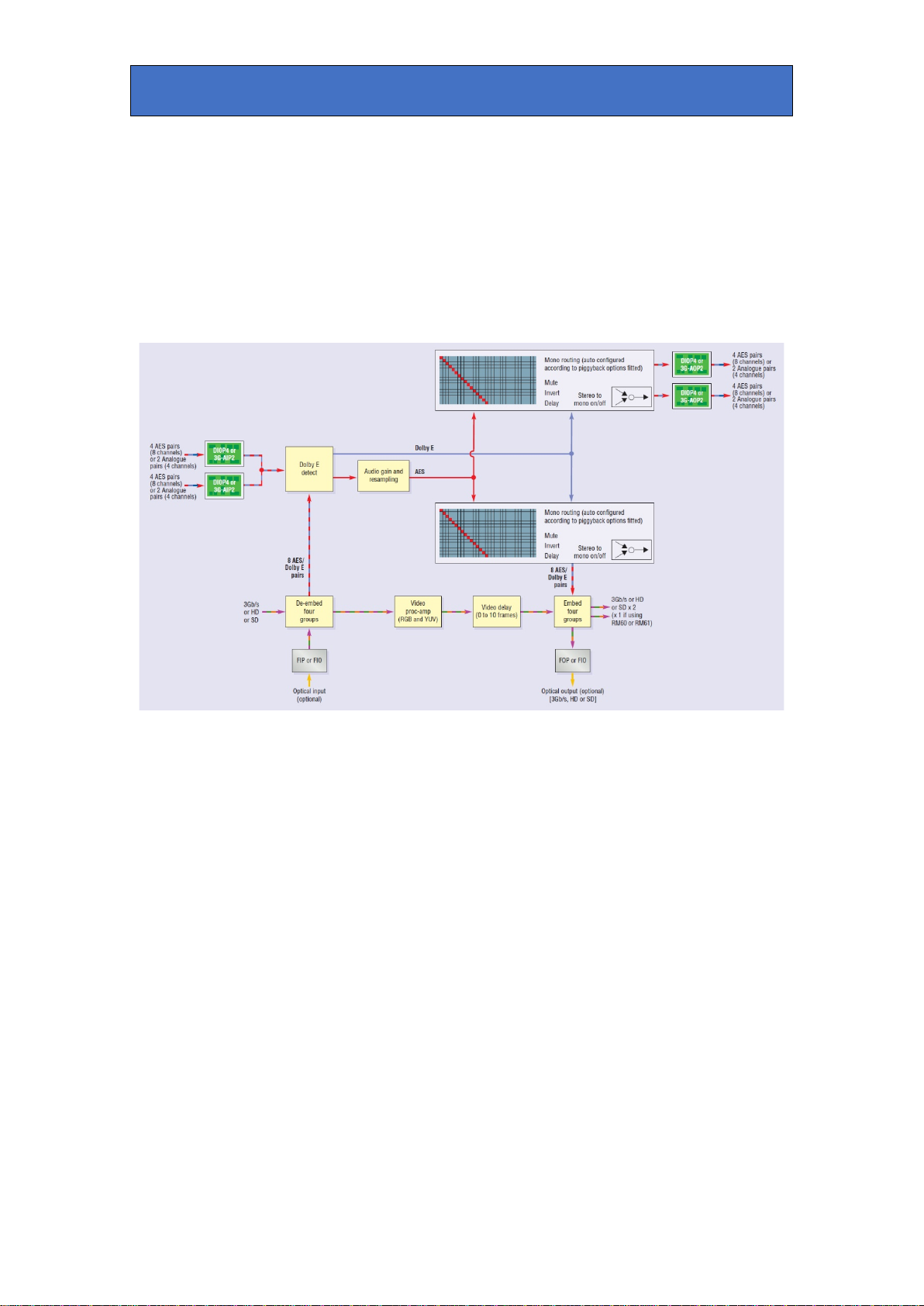
TANDEM 310 functional block diagram
SDI video is cable-equalised, re-clocked and passed through a de-embedder block
where up to 16 channels of audio are extracted. The video signal is then processed
allowing for adjustment of video gain, black level and independent RGB and YUV
gains. This is followed by up to ten frames of delay. The video is then passed
through the embedder block where up to 16 audio channels are inserted.
All input audio from both external (up to 16 channels via the optional plug-in input
piggyback) and de-embedded sources (16 channels) are passed to audio
processing blocks where gain and delay adjustments are made after re-sampling
The outputs of the audio processing block are inputs to two independent 32x16
routers which feed the optional plug-in output piggybacks and the embedding block.
In this way any of the 32 sources can be output or embedded.
TANDEM 310 User Manual R1.46 04 July 2019

Crystal Vision Hardware installation
2Hardware installation
2.1 Board configuration
TANDEM 310 main board top-side
Note: The potentiometers P1, P2, P3 and P4 have been factory set and should NOT be
adjusted.
Holes marked ‘A’ are for the fitting of the Dolby E decoder sub-board.
Holes marked ‘B’ are for the fitting of the I/O piggybacks.
Link Configuration
There are four user-settable links on the TANDEM 310. These are PL2-5, all other links should be
left in the position shown in the above picture. PL2-5 set whether the board’s GPI inputs are used
as GPIs or as an extra serial I/O port.
Link Towards front of board or Up Towards the rear of board or Down
J1 Unused Unused
J9
Debug mode – forces board’s IP address
to be 10.0.0.201
Normal mode (factory set, do not alter)
PL2
GPI 1 Input = RS422 Rx+
GPI 1 Input = GPI 1
PL3
GPI 2 Input = RS422 Rx-
GPI 2 Input = GPI 2
PL4
GPI 3 Input = RS422 Tx+
GPI 3 Input = GPI 3
PL5
GPI 4 Input = RS422 Tx-
GPI 4 Input = GPI 4
TANDEM 310 User Manual R1.47 04 July 2019
Crystal Vision Hardware installation
2.2 Input and output piggyback boards
The main TANDEM 310 board has two positions where one of three types of I/O
module can be plugged to enable analogue or digital input and output.
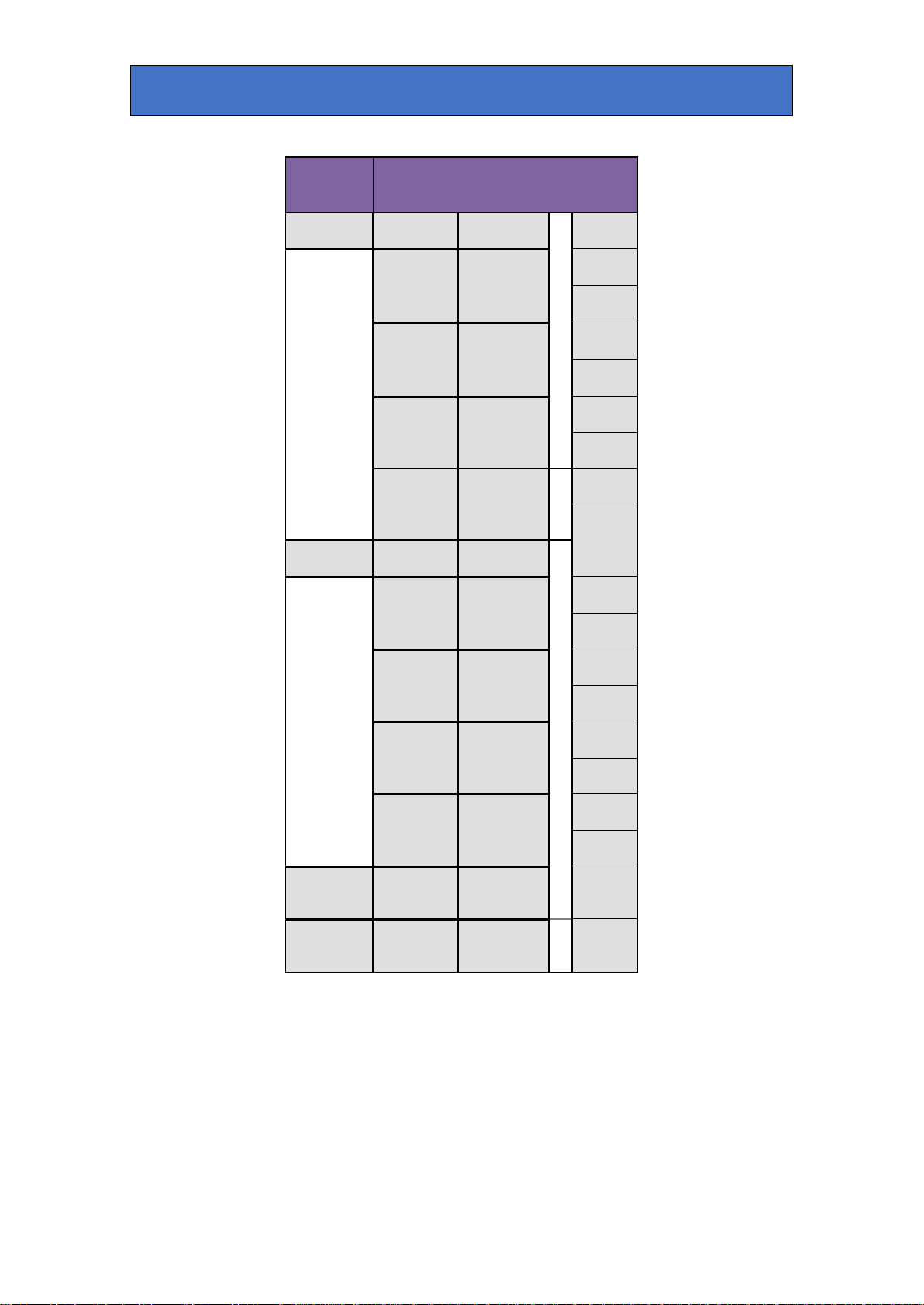
The three types of piggybacks are 3G-AIP2, 3G-AOP2 and DIOP4. The following
table shows the legal combinations of piggybacks that can be fitted into front and
rear positions:
FRONT none DIOP4 3G-
AIP2 3G-
AOP2 DIOP4 DIOP4 DIOP4 3G-
AIP2 3G-
AIP2 3G-
AOP2
REAR none none none none DIOP4 3G-
AIP2 3G-
AOP2 3G-
AIP2 3G-
AOP2 3G-
AOP2
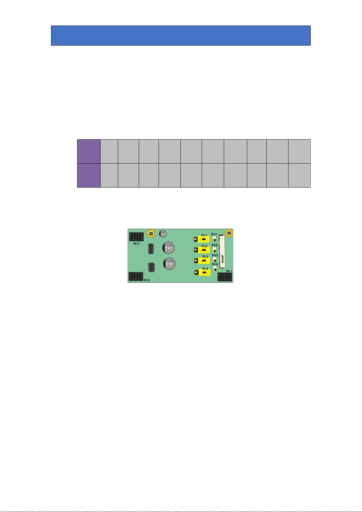
3G-AIP2 Analogue Input
This analogue module has four balanced audio inputs. The links PL1-4 allow 0dBFS
to be set to +18dBu (to the right, towards SK1) or +24dBu (to the left, towards
SK2/3). The adjacent potentiometers RV1-4 are factory set and should NOT be
adjusted.
TANDEM 310 User Manual R1.48 04 July 2019

Crystal Vision Hardware installation
3G-AIP2 Channel number Link number
CH1 PL1
CH2 PL2
CH3 PL3
CH4 PL4
Table showing links controlling the input gain of the 3G-AIP2 channels
3G-AOP2 Analogue Output
This analogue piggyback has four balanced audio outputs. The links PL1-4 set
0dBFS to +18dBu (to the right, towards SK2/3) or +24dBu (to the left, towards SK1).
The four potentiometers P1-P4 are factory set and should NOT be adjusted.
Table showing links controlling the output gain of the 3G-AOP2 channels
DIOP4 AES I/O
This digital audio piggyback has four AES stereo pairs that are individually
configured as inputs or outputs by software. There are no links or user-adjustments
on this card.
3G-AOP2 Channel number Link number
CH1 PL1
CH2 PL2
CH3 PL3
CH4 PL4
TANDEM 310 User Manual R1.49 04 July 2019

Crystal Vision Hardware installation
Fitting the I/O piggybacks onto the main board
Example showing 3G-AIP2 and 3G-AOP2 piggybacks fitted
The I/O piggybacks plug onto the main board such that main board plugs J3, J4, J5
and J6, J7, J8 align with piggyback sockets SK2, SK3, SK1. With the component
side of the module top-most, align the piggyback sockets carefully with the plugs
and push firmly. Insert the plastic rivets supplied with the fitting kit through the main
board from the underside so they protrude through the piggyback board, then push
the rivet peg firmly to splay the end to lock the piggyback board in position.
Note: The position that the piggyback is fitted determines the function of the
rear module connectors.
Front edge LEDs
LED1
LED2
LED3
LED4
LED5
On if power
supply OK On if Dolby not 5.1 On if error occurs
in audio content On if Vertical
frame sync error Bitstream Format
OFF = Dolby E,
ON = other
There are 13 links that are factory set and should NOT be moved. There is one
potentiometer P2 that is factory set and should NOT be adjusted.
TANDEM 310 User Manual R1.410 04 July 2019

Crystal Vision Rear modules and signal I/O
3Rear modules and signal I/O
The 2U Indigo 2 frames will house up to 12 single height modules and dual power
supplies. The 1U Indigo 1 frames will house six single height modules and a single or
dual power supply. The Indigo DT desk top boxes have a built-in power supply and
will house up to two single height modules. All modules can be plugged in and
removed while the frame is powered without damage.
Note: For details of fitting rear connectors please refer to the appropriate frame manual.
TANDEM 310 can support the following rear modules: RM47, RM60, RM61, RM70
and RM74.
3.1 Rear module connections with RM47
The RM47 being a single height module will allow maximum packing density with the
maximum number of outputs available. Eight AES stereo pairs or eight mono
analogue channels are presented as balanced I/O on the 26-way high density D-Type
connector.
RM47 rear module connector
Description
RM47
•12 per Indigo 2 frame
•Six per Indigo 1 frame
•Two per Indigo DT
•All frame slots can be used
BNC connections
BNC I/O assignment
SDI IN 3G/High Definition/Standard Definition serial digital input
NC No user connection
SDI OUT(A) 3G/High Definition/Standard Definition serial digital output
SDI OUT(B) 3G/High Definition/Standard Definition serial digital output
26-way D-Type Audio Connections
The 26-way audio ‘D’ connector RM47 module can be used for analogue or digital, inputs or
outputs – or a mixture of both depending on the audio piggybacks fitted. Half of the I/O
channels on the rear module are connected to the front I/O (nearest handle) module position
and the remainder to the rear module position. The DIOP4 will normally be configured as 110
ohm balanced operation when using this rear module.
TANDEM 310 User Manual R1.411 04 July 2019
Crystal Vision Rear modules and signal I/O
Module
position I/O Pin-out
GND 1
Analogue
audio 1/
AES1 {
+ 2
- 3
Analogue
audio 2/
AES2 {
+ 4
Front - 5
Analogue
audio 3/
AES3 {
+ 6
- 7
Analogue
audio 4/
AES4 {
+ 8
- 18
GND 9
Analogue
audio 5/
AES5 {
+ 14
- 15
Analogue
audio 6/
AES6 {
+ 10
Rear - 11
Analogue
audio 7/
AES7 {
+ 16
- 17
Analogue
audio 8/
AES8 {
+ 12
- 13
GND 19, 20,
23, 24
NC 21, 22,
25, 26
RM47 audio I/O connector wiring - All audio balanced signals can be either input or output
depending on I/O module fitted.
TANDEM 310 User Manual R1.412 04 July 2019

Crystal Vision Rear modules and signal I/O
3.2 Rear module connections with RM60
The RM60 being a single height module will allow maximum packing density with the
option of an optical connection. Eight AES stereo pairs or eight mono analogue
channels are presented as balanced I/O on the 26-way high density D-Type
connector.
RM60 rear module connector Description
RM60
•12 per Indigo 2 frame
•Six per Indigo 1 frame
•Two per Indigo DT
•All frame slots can be used
BNC connections
BNC I/O assignment
SDI IN 3G/High Definition/Standard Definition serial digital input
SDI OUT 3G/High Definition/Standard Definition serial digital output
OPTICAL I/O SC optical connector. Input or output depending on optical module fitted.
26-way D-Type Audio connections
The 26-way audio ‘D’ connector RM60 module can be used for analogue or digital, inputs or
outputs – or a mixture of both depending on the I/O modules fitted. Half of the I/O channels on
the rear module are connected to the front I/O (nearest handle) module position and the
remainder to the rear module position. The DIOP4 will normally be configured as 110 ohm
balanced operation when using this rear module.
TANDEM 310 User Manual R1.413 04 July 2019

Crystal Vision Rear modules and signal I/O
Module
position I/O Pin-out
GND 1
Analogue
audio 1/
AES1 { + 2
- 3
Analogue
audio 2/
AES2 { + 4
Front - 5
Analogue
audio 3/
AES3 { + 6
- 7
Analogue
audio 4/
AES4 { + 8
- 18
GND 9
Analogue
audio 5/
AES5 { + 14
- 15
Analogue
audio 6/
AES6 { + 10
Rear - 11
Analogue
audio 7/
AES7 { + 16
- 17
Analogue
audio 8/
AES8 { + 12
- 13
GND 19, 20,
23, 24
NC 21, 22,
25, 26
RM60 audio I/O connector wiring - All audio balanced signals can be either input or output
depending on I/O module fitted.
TANDEM 310 User Manual R1.414 04 July 2019

Crystal Vision Rear modules and signal I/O
3.3 Rear module connections with RM61
The RM61 is a dual height module presenting the eight channels of unbalanced audio
AES stereo pairs on 75 ohm BNC connectors. The DIOP4 I/O module(s) must be
used with this rear module as there is no provision for analogue audio I/O.
RM61 rear module connector
Description
RM61
•Six per Indigo 2 frame
•Three per Indigo 1 frame
•One per Indigo DT
•Alternate frame slots can be
used
BNC Connections
BNC I/O assignment
SDI IN 3G/High Definition/Standard Definition serial digital input
NC No user connection
AES5 I/O AES5 stereo pair 75 ohm input/output
AES1 I/O AES1 stereo pair 75 ohm input/output
SDI OUT 3G/High Definition/Standard Definition serial digital output
OPTICAL I/O SC optical connector. Input or output depending on optical module fitted
AES8 I/O AES8 stereo pair 75 ohm input/output
AES7 I/O AES7 stereo pair 75 ohm input/output
AES6 I/O AES6 stereo pair 75 ohm input/output
AES4 I/O AES4 stereo pair 75 ohm input/output
AES3 I/O AES3 stereo pair 75 ohm input/output
AES2 I/O AES2 stereo pair 75 ohm input/output
TANDEM 310 User Manual R1.415 04 July 2019
Crystal Vision Rear modules and signal I/O
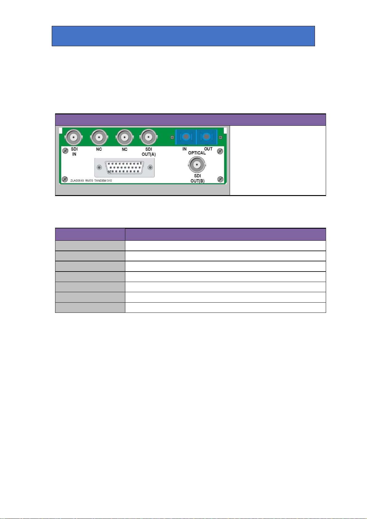
3.4 Rear module connections with RM70
The RM70 being a dual height module will allow maximum packing density with the
option of a dual optical connection. Eight AES stereo pairs or eight mono analogue
channels are presented as balanced I/O on the 26-way high density D-Type
connector.
RM70 rear module connector Description
RM70
•Six per Indigo 2 frame
•Three per Indigo 1 frame
•One per Indigo DT
•Alternate frame slots can be
used
BNC Connections
BNC I/O assignment
SDI IN
3G/High Definition/Standard Definition serial digital input
NC No user connection
NC No user connection
SDI OUT (A) 3G/High Definition/Standard Definition serial digital output
OPTICAL IN
SC optical input connector
OPTICAL OUT SC optical output connector
SDI OUT (B) 3G/High Definition/Standard Definition serial digital output
TANDEM 310 User Manual R1.416 04 July 2019

Crystal Vision Rear modules and signal I/O
26-way D-Type Audio connections
Module
position I/O Pin-out
GND 1
Analogue
audio 1/
AES1 { + 2
- 3
Analogue
audio 2/
AES2 { + 4
Front - 5
Analogue
audio 3/
AES3 { + 6
- 7
Analogue
audio 4/
AES4 { + 8
- 18
GND 9
Analogue
audio 5/
AES5 { + 14
- 15
Analogue
audio 6/
AES6 { + 10
Rear - 11
Analogue
audio 7/
AES7 { + 16
- 17
Analogue
audio 8/
AES8 { + 12
- 13
GND 19, 20,
23, 24
NC 21, 22,
25, 26
RM70 audio I/O connector wiring - All audio balanced signals can be either
input or output depending on I/O module fitted.
TANDEM 310 User Manual R1.417 04 July 2019

Crystal Vision Rear modules and signal I/O
3.5 Rear module connections with RM74
The RM74 is a dual height module presenting the eight unbalanced AES stereo pairs on 75
ohm BNC connectors. The DIOP4 I/O piggyback(s) must be used with this rear module as
there is no provision for analogue audio I/O.
RM74 rear module connector
Description
RM74
•Six per Indigo 2 frame
•Three per Indigo 1 frame
•One per Indigo DT
•Alternate frame slots can be
used
BNC Connections
BNC I/O assignment
AES5 AES5 stereo pair 75 ohm input/output
AES7 AES7 stereo pair 75 ohm input/output
AES8 AES8 stereo pair 75 ohm input/output
AES4 AES4 stereo pair 75 ohm input/output
AES3 AES3 stereo pair 75 ohm input/output
AES2 AES2 stereo pair 75 ohm input/output
HD SDI IN 3G/High Definition/Standard Definition serial digital input
AES6 AES6 stereo pair 75 ohm input/output
NC No Connection
HD SD OUT 1 3G/High Definition/Standard Definition serial digital output
HD SD OUT 2 3G/High Definition/Standard Definition serial digital output
AES1 AES1 stereo pair 75 ohm input/output
TANDEM 310 User Manual R1.418 04 July 2019

Crystal Vision General Purpose Interface
4General Purpose Interface
4.1 Introduction
Each frame slot has up to six connections ‘a-f’ for GPI control and monitoring. These
connections are available at the rear of the frame on the 26-way D-Type remote connectors.
TANDEM 310 has four GPI inputs and two GPI outputs.
Each General Purpose Interface (GPI) input is fitted with a 6800Ω resistor connected to the
internal +5V and in the following table, this equates to logic ‘H’. With the GPI preset recall
lines set to ‘level’ mode and no connections (logic ‘HHHH’), preset 1 will be selected. With the
GPI preset recall lines set to ‘pulse’ mode, the GPI will be activated whenever a bit is pulled
low but no change to the preset selection will occur when all bits return to logic ‘HHHH’. Note
that preset 16 is not accessible in pulse mode.
Note: Because the GPI inputs are sampled in the vertical interval it is recommended that in
‘pulse’ mode, the GPI should be asserted at least 2mS before the start of vertical sync to
ensure stability and held active for at least 40mS.
See Presets for details of inverting the GPI preset logic.
Each General Purpose Interface output (GPO) has a 270Ω resistor in series with its output.
This allows for an external LED to be driven, connected to a DC voltage of +5V.
The GPI inputs can be programmed to automatically recall a previously saved preset
configuration. The 16 user preset configurations are selected using binary notation. The two
outputs can be programmed to assert themselves for a number of different alarm conditions.
GPI Low (<1V) High (+5V)
1 ‘a’ Recall preset bit 1
See following table for user preset control
2 ‘b’ Recall preset bit 2
3 ‘c’ Recall preset bit 4
4
‘d’
Recall preset bit 8
5 ‘e’ Alarms (See alarm table) Alarm condition No alarm
6
‘f’
Alarms
(See alarm table)
Alarm condition No alarm
Table showing the six GPI functions
TANDEM 310 User Manual R1.419 04 July 2019
Table of contents
Other Crystal Vision PCI Card manuals

Crystal Vision
Crystal Vision Indigo TANDEM 320 User manual

Crystal Vision
Crystal Vision Vision System SYNNER-VF User manual

Crystal Vision
Crystal Vision Indigo SYNNER 310 User manual

Crystal Vision
Crystal Vision Vision System TANDEM10-VF User manual

Crystal Vision
Crystal Vision SYNNER-E 3G User manual

Crystal Vision
Crystal Vision GPI36 User manual


