CRYSTEEL LO-BOY User manual

1644526G (406807) 2020-SEP-211
LO-BOY
TRUCK HOIST
CRYSTEEL’S
Web Site E-Mail Phone (507) 726-2728
Website: www.TBEI.com
E-mail: [email protected]
THIS MANUAL MUST BE INCLUDED WITH THE VEHICLE
AFTER COMPLETING THE INSTALLATION.

1644526G (406807) 2020-SEP-2121644526G (406807) 2020-SEP-213
DATE PURCHASED __________________________________________________________________
HOIST SERIAL NUMBER ____________________________________________________________
CYLINDER SERIAL NUMBER ______________________________________________________
DEALER __________________________________________________________________
ADDRESS __________________________________________________________________
PHONE __________________________________________________________________
FOREWORD
Crysteel’s LoBoy hoists have been designed for use on single-axle trucks with cab-to-axle dimensions of
60 to 150 inches for use with bodies of 8 through 18 feet in length and on tandem axle trucks with cab-to-
tandem center dimensions of 102 to 126 inches for use with bodies from 14 to 18 feet in length. Bodies
normally used with these hoists are grain bodies and platforms. This manual contains the information
needed for the proper installation and operation of these hoists.
These instructions are for installing and maintaining all models of LoBoy hoists. With proper installation,
use, and regular maintenance, Crysteel’s LoBoy truck hoists will give many years of trouble free service.
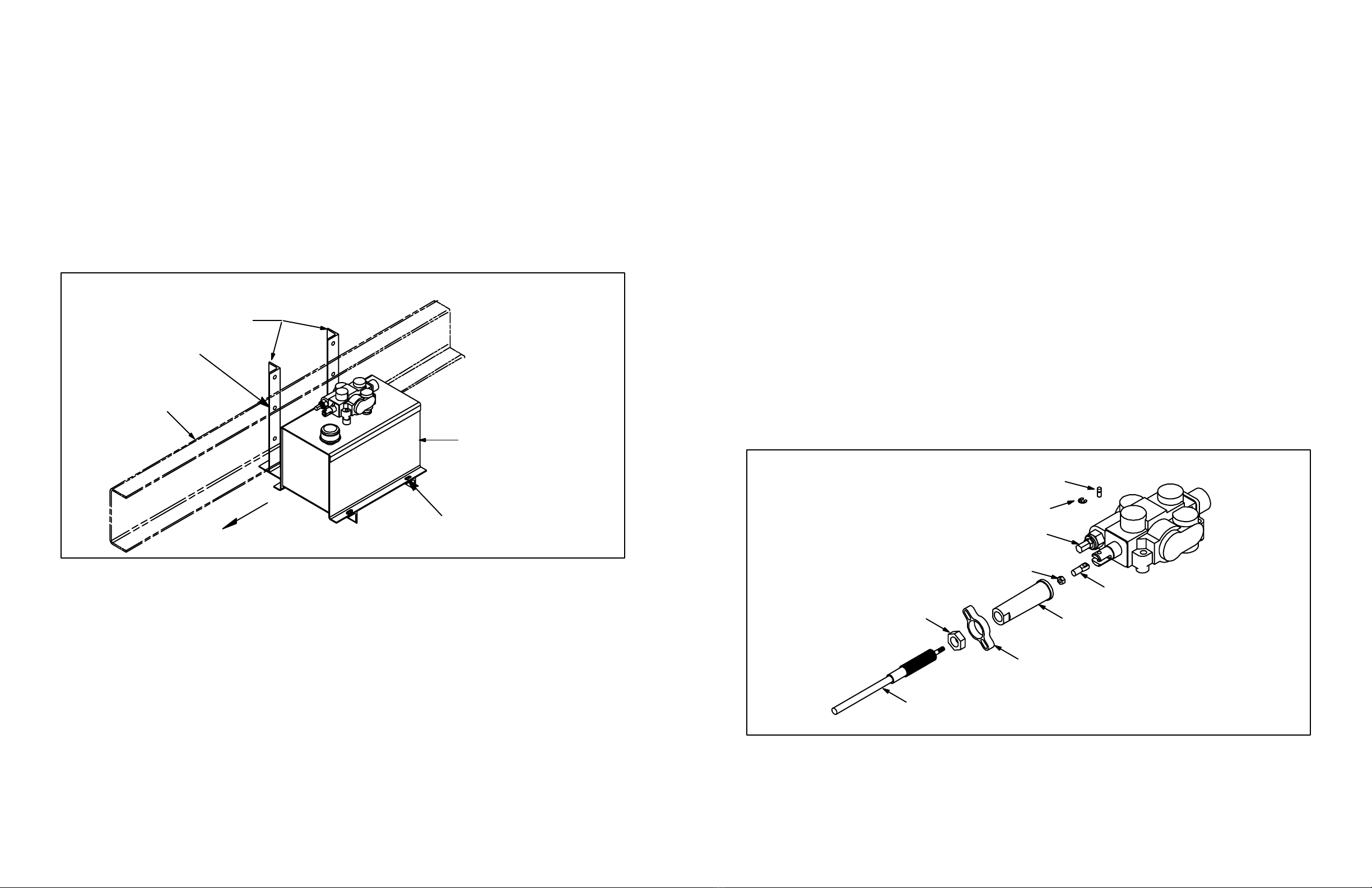
When ordering parts, be sure to give serial number of hoist and cylinder. The serial number of the hoist
is stamped into the hoist frame near the base end of the cylinder. The serial number of the cylinder is
stamped on the barrel of the cylinder near the base. For future reference, copy these numbers NOW in the
space provided above. Order parts by number and description as given in the parts listing in this manual.
1. Engage PTO from cab and adjust engine speed to fast idle.
OPERATIONANDUSE
SOMEDO’SANDDON’TSFORSAFEANDLONGSERVICE
1. Usetheproperhydraulicuid.KEEPITCLEAN.Remembertochangeitregularly.
2. ALWAYS operate the hoist from inside the cab of the truck.
3. If the hydraulic hose connections are correct, the hoist should raise when the hoist control
lever is pulled back, hold when the lever is in the center detent, and lower when the lever
is pushed forward.
4. To raise the hoist, pull the control lever back. To hold the body in a raised position, place
the control lever in its center detent position. To lower the hoist, push the control lever
forward.
5. ALWAYS return the hoist control lever to its center detent position after each use.
6. Whenthehoistcylinderreachestheendofthestroke,oilwillowthroughtheautomatic
bypass valve built into the piston inside the cylinder and return to the reservoir.
7. It is advisable to run the PTO to “power down” or lower the hoist because this will act as
an hydraulic lock to hold the hoist in the lowered position. It is not necessary to do this,
however,becausethereservoirhassucientcapacitywhetherornotthehoistispowered
down.Youwillbenetfromtheadvantagesofthedoubleactinghoistonlyifyoupower
down.
8. To make use of the hydraulic lock feature, place the hoist control lever in the center hold
position after the hoist is powered down. This places the pressure on the valve, where it
belongs, not on the pump.
9. DO NOT LEAVE THE PTO IN GEAR WHILE TRANSPORTING. THIS CAN CAUSE
SEVERE DAMAGE TO THE PTO OR HYDRAULIC PUMP.
10.Thehydraulicsystemshouldbedrained,ushedandrelledwithproperhydraulicuid
atregularintervals.CAUTION:NEVERusehydraulicBRAKEFLUIDinthehydraulic
system.
11.Afteraddingorreplacingthehydraulicuid,cyclethehoistseveraltimestoremoveair
from the cylinders and hydraulic hoses.
2. Lubricateallgreasettingsevery100cyclesoreverytwomonths.Infrequentorinsu-
cient lubrication will cause hoist failure and possibly injury or death.
3. ALWAYS carefully block up the body, using the body prop, before working under it.
4. Do not “race” the engine when unloading.
5. Do not load the hoist beyond its capacity.
6. DO NOT tamper with the hydraulic relief valve. This will void the warranty. It can cause
severe damage to the hoist and cylinder.
7. Never leave the PTO in gear while transporting. It could ruin the hydraulic pump, the PTO
or the transmission.
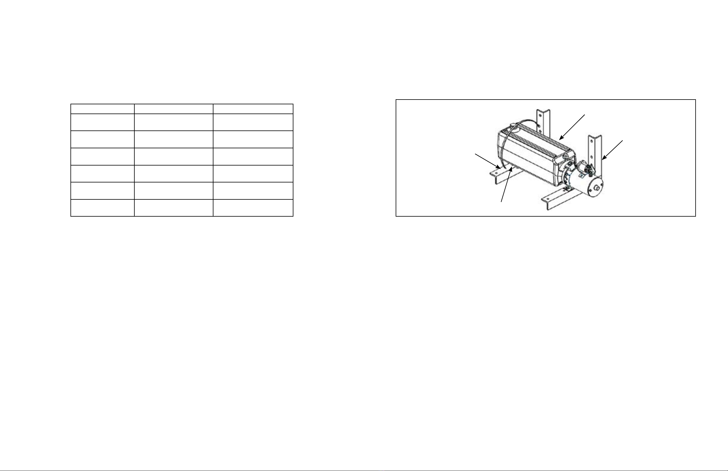
8. Checkallboltsandttingsregularly.Keepthemtight.Seetableonpage4fortorqueval-
ues.
9. Alwaysoperatehoistonarmandlevelsurface.
10. Always make sure area around truck is clear and safe for hoist operation and dumping.

1644526G (406807) 2020-SEP-2141644526G (406807) 2020-SEP-215
TABLE OF CONTENTS
FOREWORD 2
SOME DO’S AND DON’TS FOR SAFE AND LONG SERVICE 3
OPERATION AND USE 3
LOCATE AND INSTALL REAR HINGE 6
LOCATE HOIST 7
MOUNT HOIST FRAME 8
HYDRAULIC SYSTEMS 8
INSTALL GEAR PUMP - BERT, CHARLIE & DANIEL 8
INSTALL GEAR PUMP - DAVID, ERNIE & FLOYD 9
MOUNT RESERVOIR/VALVE ASSEMBLY - BERT, CHARLIE & DANIEL 9
MOUNT RESERVOIR/VALVE ASSEMBLY - DAVID, ERNIE & FLOYD 10
INSTALL HOIST CONTROL 11
INSTALL HOSES - BERT, CHARLIE & DANIEL 12
INSTALL HOSES - DAVID, ERNIE & FLOYD 13
ADD HYDRAULIC FLUID 14
ELECTRIC POWER UNIT MOUNTING - GENERAL 15
INSTALL HOSES - SINGLE-ACTING 16
INSTALL HOSES - DOUBLE-ACTING 17
ELECTRIC DOUBLE-ACTING 17
ADD HYDRAULIC FLUID 18
MOUNT BODY 19
INSTALL BODY GUIDE PLATES 19
INSTALL BODY PROP 20
INSTALLGREASEZERKSANDLUBRICATE 21
MOUNT DECALS 22
HOIST PARTS - BERT, CHARLIE, DANIEL, DAVID, ERNIE & FLOYD 23
CYLINDER PARTS 25
HYDRAULIC SYSTEM PARTS - BERT, CHARLIE, DANIEL 26
HYDRAULIC SYSTEM PARTS - DAVID, ERNIE, FLOYD 29
CAPACITY FORMULA 32
SPECIFICATIONS 32
INSTALLATION INSTRUCTIONS
GENERAL INFORMATION
It is a good idea to look through these installation instructions before beginning to mount the hoist and
hydraulic system.
When welding, protect the truck’s electrical, air and brake systems by disconnecting, removing or cover-
ing.Tightenallnutsandboltstoaconsistentlevel.Usethefollowingtablefortorquevalues.
Size Grade2Torque Grade5Torque Grade8Torque
1/4-20 3-4 lb-ft 6-7 lb-ft 10-11 lb-ft
1/4-28 4-5 lb-ft 8-9 lb-ft 11-12 lb-ft
5/16-18 8-9 lb-ft 14-15 lb-ft 21-22 lb-ft
5/16-24 9-10 lb-ft 15-16 lb-ft 21-22 lb-ft
3/8-16 17-18 lb-ft 24-26 lb-ft 37-40 lb-ft
3/8-24 19-20 lb-ft 28-30 lb-ft 40-43 lb-ft
1/2-13 38-42 lb-ft 60-65 lb-ft 90-100 lb-ft
1/2-20 43-47 lb-ft 70-75 lb-ft 95-105 lb-ft
5/8-11 75-80 lb-ft 122-130 lb-ft 180-190 lb-ft
5/8-18 85-90 lb-ft 145-150 lb-ft 200-210 lb-ft
3/4-10 132-140 lb-ft 220-230 lb-ft 315-330 lb-ft
3/4-16 152-160 lb-ft 250-260 lb-ft 355-370 lb-ft
Thefollowingabbreviationsareusedindescribinghydraulicttings.
ORBM O-Ring Boss - Male Thread
NPTM Pipe - Male Thread
NPTF Pipe - Female Thread
JICM JIC 37° - Male Thread
JICF JIC 37° - Female Thread

1644526G (406807) 2020-SEP-2161644526G (406807) 2020-SEP-217
LOCATE AND INSTALL REAR HINGE
On single-axle trucks, the rear hinge must be located as close as possible behind the rear spring hanger.
This will be 32 to 36 inches behind the center of the rear axle. On tandem axle trucks the center of the rear
hinge should be located 42 to 50 inches behind the center of the rear tandems. Mark the rear of the truck
frame for notching as shown in Figure 1. Notch the truck frame as marked. Make sure the rear hinge is
squarewiththetruckframeandatthecorrectheight.Thetopsurfaceoftherearhingebracketshouldbe
ushwiththetopoftheanglemountingbracketsofthehoistframeasshowninFigure1.Securelyweld
the rear hinge to the truck frame. Cap the ends of the truck frame under the rear hinge. Weld the capping
plates to the ends of the truck frame and to the bottom side of the rear hinge angle.
On tandem-axle trucks, place the gussets in the corners formed by the truck frame rail and the rear hinge
frameangle.Raisethefrontendofthegussetsoittouchesthetopangeofthetruckframerail.Besure
that the gusset does not interfere with the rear hinge operation. Securely weld the gussets to the rear hinge,
thetruckframerailandthetopangeofthetruckframerail.
LOCATEHOIST
Determine where to mount the hoist on the truck. Please refer to the chart in Fig. 4 for the relationship
between dump angle and “D” dimension. Measure forward from the center of the rear hinge pin and mark,
on the truck frame, the location of the front crosstube of the hoist frame. Place the hoist on the truck frame
and clamp the hoist pivot pads to the truck frame. The back end of the hoist must be supported by a cross-
member in the truck frame. The top of this crossmember may be up to 1” below the top of the truck frame.
The “CM” dimension shows the location for this crossmember. Make sure the hoist frame is centered on
andsquarewiththetruckframe.
Ifdesired,thehoistcanbeturnedendforendfora‘Reverse’mount.Thisdoesnotaecttheliftingcapac-
ity.
WARNING! LOCATING THE REAR HINGE FARTHER BACK THAN
RECOMMENDED MAY CAUSE UNDUE STRESS IN THE TRUCK FRAME,
AND MAY CAUSE INSTABILITY DURING THE LIFTING CYCLE!
96”

1644526G (406807) 2020-SEP-2181644526G (406807) 2020-SEP-219
MOUNT HOIST FRAME
Thehoistpivotpadsmustrestatonthetruckframe.Ifthehoistpivotpadssitonrivetheadsinthetruck
frame, either move the hoist or drill holes in the pivot pads to clear the rivets. On the driver’s side, clamp
the hoist mount/prop pivot the lower hoist pivot pad and to the outside of the truck frame. On the passen-
ger side, clamp a hoist mounting angle to the lower hoist pivot pad and to the outside of the truck frame.
Mark the truck frame for drilling. See Figure 5.
CAUTION: BE CAREFUL OF BRAKELINES, WIRING, ETC. INSIDE THE
TRUCK FRAME WHEN DRILLING THE TRUCK FRAME.
Drill 21/32 diameter holes in the truck frame using the hoist mounting angles as guides. Bolt the prop
pivot and mounting angle to the truck frame using 5/8 x 2 hex bolts and hex lock nuts, tightening to 180 to
190 lb-ft. Securely weld the lower hoist pivot pads to the mounting angles. DO NOT WELD THE HOIST
PIVOTPADSTOTHETRUCKFRAME!Removetheclamps.
HYDRAULIC SYSTEMS
CrysteeloersPTOdriven,gearpumphydraulicsystemsforusewithallmodelsofLoBoyhoists.Crys-
teelalsooerselectricpowerunits,bothsingle-anddouble-acting,forallmodelsexceptH-25(Henry).
Mounting instructions can be found on the pages shown:
MOUNT RESERVOIR/VALVEASSEMBLY- B-5 (BERT), C-8 (CHARLIE)& D-9
(DANIEL)
Determine which side of the truck to mount the reservoir/valve assembly. The same side as the PTO open-
ingonthetransmissionwouldbeideal.Using3/8x1”capscrews,atwashersandhexlocknuts,boltthe
reservoir mounting angles to the reservoir/valve assembly so the exposed end of the valve spool is toward
the cab (See Fig. 7). This makes it much easier to connect the valve control cable to the valve. Place this
assembly against the outside of the truck frame on the same side as the pump. Mark the truck frame for
drilling using the mounting angles as guides. Make sure there is enough clearance for hot exhaust pipes.
THE ENGINE EXHAUST MUST NEVER BLOW DIRECTLY ONTO THE RESERVOIR/VALVE AS-
SEMBLY.
PTO driven Gear Pump with Remote Reservoir/Valve Page 8
Electric Pumps - General Page 15
Electric Pumps - Single-Acting Page 16
Electric Pumps - Double-Acting Page 17
INSTALLGEAR PUMP- B-5(BERT),C-8(CHARLIE)& D-9(DANIEL)
ThegearpumphasanSAE`A’mountingconguration,an11-toothsplinedshaftandatwo-boltmounting
ange,andisassembledforcounterclockwiserotation.Note:ThispumpwillmountdirectlytoChelsea’s
output type `AD’ or Muncie’s output type `T’. Crysteel Manufacturing recommends a PTO ratio of 100-
120%.Thisassuresaminimumpumpoperatingspeedof600RPM.CHECKTHEROTATIONOFTHE
PTO!Ifitisoppositeoftheengine,thenthepumpcanbeusedasitis.IfthePTOrotationisthesameas
the engine, then the pump will need to be reversed. (See instructions included with the pump.) Bolt the
gearpumptothePTOoutputangeusing3/8x1”capscrewsandlockwashers.
INSTALLGEAR PUMP- D-10 (DAVID), E-15 (ERNIE)& F-18 (FLOYD)
The gear pump for the D-10 (David), E-15 (Ernie) and F-18 (Floyd) hoists has an SAE `B’ mounting
conguration,a13toothsplinedshaftandafour-boltmountingange,andisassembledforrotationin
eitherdirection.NOTE:ThispumpwillmountdirectlytoChelsea’soutputtype`XK’orMuncie’soutput
type `D’. Crysteel Manufacturing recommends a PTO ratio of 100-120%. This assures a minimum pump
operatingspeedof600RPM.BoltthegearpumptothePTOoutputangeusing1/2x11/4capscrews
and lock washers.
CAUTION: BE CAREFUL OF BRAKELINES, WIRING, ETC. INSIDE THE
TRUCK FRAME WHEN DRILLING THE TRUCK FRAME.

1644526G (406807) 2020-SEP-2110 1644526G (406807) 2020-SEP-2111
Drill 17/32” holes in the truck frame and bolt the reservoir/valve assembly in place using 1/2 x 2” cap
screws and hex lock nuts, tightening to 90 to 100 lb-ft.
MOUNTRESERVOIR/VALVEASSEMBLY-D-10(DAVID),E-15(ERNIE)&F-18
(FLOYD)
The reservoir/valve assembly should be mounted on the same side of the truck as the pump with the ex-
posed end of the valve spool toward the front. Bolt the mounting angles to the reservoir/valve assembly
using3/8x1capscrews,atwashersandhexlocknuts,tighteningto24to26lb-ft.Placethereservoir/
valve assembly inside the truck frame and raise it as high as possible. See Figure 5. (There is no drive line
to align and the reservoir should be higher than the pump for reliable performance.) Make sure there is
enough clearance for the truck drive line and hot exhaust pipes. THE ENGINE EXHAUST MUST NEV-
ER BLOW DIRECTLY ONTO THE RESERVOIR/VALVE ASSEMBLY. Clamp the mounting angles to
the truck frame and mark the truck frame for drilling using the pump mounting angles as guides.
INSTALL HOIST CONTROL
Mount the Hoist Control decal on the pedestal taking care to align the holes for the PTO cable and indicator
light. Temporarily assemble the valve control head to the pedestal using 5/16 x 2 1/2 machine screws and
hexnuts.Placethisassemblyontheoorofthecab.Thepedestalandvalvecontrolshouldangleforward.
This makes it convenient for the operator to pull the hoist control lever back to raise the hoist. Make sure
there is enough room to operate the valve control and gear shift lever and to adjust the seat. Check below
theoorforobstructionsandcablerouting.Relocatethevalvecontrolifnecessary.Marktheoorusing
the pedestal as a template and drill 11/32” holes for the mounting screws and a 3/4” hole for the control
cable. Assemble the control cable to the valve control head and assemble the valve control head and cover
to the pedestal using 5/16 x 2 1/2 machine screws and hex lock nuts. Insert the control cable through the
holeintheoorandmountthepedestaltotheoorusing5/16x1/2hexheadcapscrews,clampingplate
(undertheoor)andhexlocknuts.Makesurethevalvecontrolleverisinitscenterdetentposition.Keep
the control cable away from hot exhaust pipes and rotating drive shafts. The control cable should not have
any sharp bends or kinks in it (these will make the control harder to operate).
Install the 3/4” hex jam nut onto the valve end of the control cable and turn it past the threads. Insert the
end of the cable through the bonnet clamp. Install the bonnet onto the control cable and turn it past the
threads also. Install the 1/4” hex jam nut and terminal eye on the core rod of the cable; lock the terminal
eye to the core rod of the cable using the hex jam nut. Place the terminal eye in the slot of the valve spool;
insert the short pin through the valve spool and terminal eye and secure it in place with the `E’ ring. Thread
thebonnetontotheendofthecablesoitrmlytouchestheendofthevalve.(Donotover-orunder-tighten
the bonnet as either would move the valve spool out of its neutral position.) Remove two cap screws from
opposite corners of the seal retainer plate. Slide the bonnet clamp onto the bonnet and secure it to the valve
usingthe1/4x11/4capscrews,lockwashersandatwashers.Lockthebonnettothecableusingthe
3/4” hex jam nut. (See Fig. 8.)
CAUTION: BE CAREFUL OF BRAKELINES, WIRING, ETC. INSIDE THE
TRUCK FRAME WHEN DRILLING THE TRUCK FRAME.
FIG. 7
Drill 17/32” holes in the truck frame and bolt the reservoir/valve assembly in place using 1/2 x 2” cap
screws and hex lock nuts, tightening to 90 to 100 lb-ft.
FIG. 8
TERMINAL EYE
HEX JAM NUT 1/4-28
BONNET
HEX JAM NUT 3/4-16
BONNET CLAMP
CONTROL CABLE
PIN
`E'-RING
CONTROL VALVE

1644526G (406807) 2020-SEP-2112 1644526G (406807) 2020-SEP-2113
INSTALLHOSES- B-5(BERT),C-8(CHARLIE)&D-9(DANIEL)
Study Fig. 9 very carefully before connecting hoses. Install a 90° street elbow and a 3/4” hose barb in the
suction port on the bottom of the reservoir. Install a 1 1/16 ORB x 3/4” hose barb in the suction port of
the pump and install a 3/4” ID suction hose. Secure the suction hose in place using hose clamps. Install a
1 1/16 ORB x 3/8 NPT adapter and a 3/8 NPT 90° swivel adapter in the `IN’ port of the control valve and
a 7/8 ORB x 3/8 NPT adapter in the pressure port of the pump. Connect a 72” long 3/8” hose between the
pump and the valve.
Install 3/4 ORB male x 3/4 JIC male 90° adapters in the work ports of the control valve and 9/16 ORB
male x 3/4 JIC male straight adapters in the ports on the cylinder. Connect the shorter 3/8” hose with 3/4
JICttingsfromthe`B’portonthecontrolvalvetothebaseendportonthecylinder;connectthelonger
3/8”hosewith3/4JICttingsfromthe`A’porttotherodendport.Thiswillraisethehoistwhenthecon-
trol lever is pulled back and lower it when pushed forward.
INSTALLHOSES - D-10 (DAVID), E-15 (ERNIE)& F-18 (FLOYD)
Study Fig. 10 very carefully before connecting the hoses. Install a 90° street elbow and a hose barb in the
suction port on the bottom of the reservoir. Install a hose barb in the suction port of the pump and install
the suction hose. Secure the suction hose in place using hose clamps.
Install a 90°swivel adapter in the `IN’ port of the control valve and install a reducing adapter in the pres-
sure port of the pump. Install the 1/2” ID, 72” long hose (3500 psi minimum pressure rating) from the
pump to the valve. Install 7/8 ORB male x 3/4 JIC male 90° adapters in the work ports of the control valve.
Install 3/4 ORB male x 3/4 JIC male straight adapters in the ports on the cylinder.
Connecttheshorter3/8”hosewith3/4JICttingsfromthebaseendportofthecylindertothe`B’porton
thecontrolvalve.Connectthelonger3/8”hosewith3/4JICttingsfromtherodendportofthecylinder
to the `A’ port on the control valve. This will raise the hoist when the control lever is pulled back and lower
it when pushed forward.
NOTE: The `A’ port is the `power-down’ port and has a pressure of only 500-1000 PSI; the `B’ port has
full system pressure.
NOTE: The `A’ port is the `power-down’ port and has a pressure of only 500-1000 PSI; the `B’ port has
full system pressure.

1644526G (406807) 2020-SEP-2114 1644526G (406807) 2020-SEP-2115
ADDHYDRAULICFLUID
UseanISO32gradehydraulicuidwhichcontainscorrosionandoxidationinhibitorsandafoamdepres-
sant.ThisisapproximatelytheequivalentofSAE10Worlighterweightoil.Initiallyllthereservoir
withthequantitiesgivenbelow.DONOTOVERFILLTHERESERVOIR!
KEEPTHEOILCLEAN! USECLEANCONTAINERS,FUNNELSANDOTHER
EQUIPMENT!
HOIST MODEL RESERVOIR SIZE FLUID REQUIRED
B-5 (BERT) 15 QUARTS 10 QUARTS
C-8 (CHARLIE) 15 QUARTS 10 QUARTS
D-9 (DANIEL) 15 QUARTS 10 QUARTS
D-10 (DAVID) 6 GALLONS 4 GALLONS
D-15 (ERNIE) 6 GALLONS 4 GALLONS
F-18 (FLOYD) 8 GALLONS 5.5 GALLONS
NOTE: If the pump does not pump oil, pressurize the reservoir and engage the pump with the engine at
slow idle. Once the pump is working, release the pressure and install the breather cap.
For the B-5 (Bert) model hoist, fully raise and lower the hoist several times to remove air from the cylinder
and hoses. For C-8 (Charlie), D-9 (Daniel), D-10 (David), E-15 (Ernie), F-18 (Floyd) and H-25 (Henry)
hoist models, fully raise the hoist and hold the hoist control in the `RAISE’ position for 20 to 30 seconds.
Thiswillremovetheairthatisinsidethecylinder(s).Lowerthehoistandchecktheuidlevelintheres-
ervoir; the reservoir should be 2/3 full with the body down.
With normal use and working conditions the hydraulic oil should be changed annually. The breather cap
should be cleaned every time the hydraulic oil is changed. With heavy use or very dusty working condi-
tions the hydraulic oil should be changed more often.
ELECTRIC POWER UNIT MOUNTING - GENERAL
The electric power unit should be mounted close behind the cab, either inside or outside the truck frame.
After determining where to mount the power unit, bolt one mounting angle to the power unit using the
3/8 x 1 hex head cap screws, tightening to 24 to 26 lb-ft. (See Fig. 11.) Clamp the mounting bracket to the
truck frame. Clamp the second mounting angle to the truck frame so it supports the far end of the reservoir.
Insert a rubber pad between the mounting angle and the reservoir; and secure it in place with a tie strap.
Mark the truck frame for drilling using the pump mounting angles as guides.
CAUTION: BE CAREFUL OF BRAKELINES, WIRING, ETC. INSIDE THE
TRUCK FRAME WHEN DRILLING THE TRUCK FRAME.
Drill 17/32” holes in the truck frame and bolt the reservoir/valve assembly in place using 1/2 x 2 cap
screws and hex lock nuts, tightening to 90 to 100 lb-ft.
For rated performance, the voltage at the power unit must be a minimum of 12VDC. This should be mea-
sured between the large terminal of the start solenoid (where the battery cable is connected) and the power
unit base. NOTE: Grounding of the power unit is just as important as the installation of the positive battery
cable. It is easier to get a good ground by using a second battery cable.
Connect the large terminal on the motor start solenoid to the positive terminal on the battery with a #0
gauge battery cable. Connect the negative terminal on the battery to the grounding hole on the power unit
with a #0 gauge battery cable. See Figure 12. Check the voltage between the large terminal on the start
solenoid and the power unit base.
Fig. 11
ELECTRIC
POWER UNIT
MOUNTING
ANGLE
RUBBER PAD
TIE STRAP

1644526G (406807) 2020-SEP-2116 1644526G (406807) 2020-SEP-2117
INSTALLHOSES-DOUBLE-ACTING
Install 9/16 ORB x 3/4 JIC straight adapters in both work ports on the electric pump. If needed, for good
hose routing, install 3/4 JIC x 3/4 JIC 90° swivel adapters to both of these adapters.
For the B-5 (Bert), C-8 (Charlie) & D-9 (Daniel) models, install 9/16 ORB male x 3/4 JIC male straight
adapters in both ports on the cylinder. For the D-10 (David), E-15 (Ernie) & F-18 (Floyd) models, install
3/4 ORB male x 3/4 JIC male straight adapters in both ports on the cylinder.
Connecttheshorter3/8”IDhosewith3/4JICttingsfromthe`C1’portonthepumptothebaseendport
onthecylinder.Connectthelonger3/8”IDhosewith3/4JICttingsfromthe`C2’porttotherodend
port. (See Fig. 14.)
NOTE: The `C2’ port is the power down port and has only 1000 PSI maximum pressure.
INSTALLHOSES-SINGLE-ACTING
Install a 9/16 ORB x 3/4-16 JIC straight adapter in the power port on the electric power unit, install a 3/4
JIC x 3/4 JIC 90° swivel adapter to this adpater and install a 1/4 NPT x 3/4-16 JIC male elbow in the port
on the angled face of the reservoir.
For the B-5 (Bert), C-8 (Charlie) & D-9 (Daniel) models, install 9/16 ORB male x 3/4 JIC male adapters
in both ports on the cylinder. For the D-10 (David), E-15 (Ernie) & F-18 (Floyd) models, install 3/4 ORB
male x 3/4 JIC male adapters in both ports on the cylinder.
Connecttheshorter3/8”hosewith3/4JICttingsfromthebaseendportofthecylindertothepowerport
ontheelectricpowerunit.Connectthelonger3/8”hosewith3/4JICttingsfromtherodendportofthe
cylinder to the port on the reservoir. (See Fig. 13.)
3/4 JICF x 3/4 JICM 90° ADAPTER
ELECTRIC SINGLE-ACTING
9/16 ORB x 3/4 JIC 90ADAPTER
1/4 NPT x 7/16 JIC 90
ADAPTER
9/16 ORBM
x 3/4 JICM
ADAPTER
ELECTRIC POWER UNIT
POWER
PORT
Fig. 14
ELECTRIC DOUBLE-ACTING
CYLINDER
ELECTRIC POWER UNIT
9/16 ORB X 3/4 JIC
ADAPTER
9/16 ORB X 3/4 JIC
ADAPTER
9/16 ORB X 3/4 JIC ADAPTER
C2 PORT (LOWER)
9/16 ORB X 3/4 JIC
ADAPTER
C1 PORT (UPPER)
Fig. 15
Fig. 12
Connect Ground Cable Connect Ground Cable
Connect Power Cable
Connect Power Cable
Double-Acting
Power Unit
Single-Acting
Power Unit
Locate the control in the cab and route the cable out of
the cab through a hole in the back of the cab. Connect
the control to the electric power unit using the 3- or
4-pin connector set.
After completing the wiring, install the motor start
switch cover over the start switch and secure with a
tie strap.
Start Switch
Cover
Fig. 13

1644526G (406807) 2020-SEP-2118 1644526G (406807) 2020-SEP-2119
For the B-5 (Bert) model hoist, fully raise and lower the hoist several times to remove air from the cylinder
and hoses.
For C-8 (Charlie), D-9 (Daniel) and D-10 (David) hoist models with single-acting power units, fully raise
the hoist and hold the `UP’ button for 20-30 seconds. This will remove the air that is inside the cylinder.
Lowerthehoistandchecktheuidlevelinthereservoir;theuidlevelshouldbewithin1”ofthetop
of the reservoir with the body down. Single-acting power units are not available for the E-15 (Ernie) and
F-18 (Floyd) hoist models.
For C-8 (Charlie) and D-9 (Daniel) hoist models with double-acting power units, fully raise the hoist and
hold the `UP’ button for 20-30 seconds. For D-10 (David), E-15 (Ernie) and F-18 (Floyd) hoist models
withdouble-actingpowerunits,raisethehoistuntilthereis2”ofATFinthereservoir.Add2quartsand
raise the hoist until there is 2” of ATF in the reservoir. Repeat this until the hoist can be fully raised. Fully
raise the hoist and hold the `UP’ button for 20-30 seconds. This will remove the air that is inside the cyl-
inder.Lowerthehoistandchecktheuidlevelinthereservoir;theuidlevelshouldbewithin1”ofthe
top of the reservoir with the body down.
Withnormaluseandworkingconditionstheautomatictransmissionuidshouldbechangedannually.
Thebreathercapshouldbecleanedeverytimetheuidischanged.Withheavyuseorverydustyworking
conditionstheuidshouldbechangedmoreoften.
MOUNTBODY
It is recommended that the body be painted before it is mounted on the truck. Place the body in position
onthetruckwiththreeinchesofclearancebehindthecab.Usetherivetstripstollthespacebetween
the longbeams and the truck frame. Use three on each side, one near the front of the body and two evenly
spaced between the hoist mount and the rear hinge. Weld them to the longbeams. Align the body long-
beams carefully with the truck frame. Securely weld the longbeams to the rear hinge brackets and to the
upper hoist pivot pads.
Ontheinsideofthelongbeams,securelyweldthelongbeamllerstothetopoftheupperhoistpivotpads
andtothetopangeofthelongbeamchannelsasshowninFigure15.ForCrysteel’sGrainTipper,place
the9inchsquareplatebetweentheangleliftbracketandtheinsideofthelongbeamasshowninFigure16.
Securely weld this plate to the longbeam and to the upper hoist pivot pad. Be sure to do this on both sides.
DO NOT WORK UNDERARAISED BODYUNLESS THE BODYIS SECURELY
BLOCKED OR PROPPED IN THE RAISED POSITION.
Seespecicationsonpage34forminimumoorheights.
INSTALLBODYGUIDEPLATES
Crysteel recommends that plates be in-
stalled on the inside of the body longbeams
to work with the body guides built into the
hoist frame to keep the body and truck
frame aligned when the body is down. (See
Fig. 17.)
ADD HYDRAULIC FLUID
UseanISO32gradehydraulicuidwhichcontainscorrosionandoxidationinhibitorsandafoamdepres-
sant.ThisisapproximatelytheequivalentofSAE10Worlighterweightoil.Dexronautomatictransmis-
sionuidcanbeusedintheelectricpowerunits.Initiallyllthehydraulicreservoirusingthefollowing
table.DONOTOVERFILLTHERESERVOIR!
Function Hoist Model Reservoir Size FluidRequired Initial Fill
Single-Acting
B-5 (Bert) 10.5 Quarts 10 Quarts 10.5 Quarts
C-8 (Charlie) 10.5 Quarts 10 Quarts 10.5 Quarts
D-9 (Daniel) 10.5 Quarts 10 Quarts 10.5 Quarts
D-10 (David) 10.5 Quarts 10 Quarts 10.5 Quarts
Double-Acting
B-5 (Bert) 7.5 Quarts 10.5 Quarts 7.5 Quarts
C-8 (Charlie) 7.5 Quarts 12 Quarts 7.5 Quarts
D-9 (Daniel) 7.5 Quarts 13 Quarts 7.5 Quarts
D-10 (David) 7.5 Quarts 13.5 Quarts 7.5 Quarts
D-15 (Ernie) 7.5 Quarts 16.5 Quarts 7.5 Quarts
F-18 (Floyd) 7.5 Quarts 20 Quarts 7.5 Quarts
KEEPTHEOILCLEAN! USECLEANCONTAINERS,FUNNELSANDOTHER
EQUIPMENT!
FIG. 17
FIG. 16
Fig. 16 Fig. 17
Fig. 18

1644526G (406807) 2020-SEP-2120 1644526G (406807) 2020-SEP-2121
INSTALLBODYPROP
The body prop is designed and intended to support an EMPTY truck body in the raised position. Use of
the body prop permits service to be performed safely beneath a raised body. It is mounted on the outside
of the truck frame on the drivers side.
1. Raise the body half way up and brace it securely before beginning installation.
2. Install the prop arm on the hoist mount / prop pivot with a 1/4 x 3 roll pin. Raise the body
prop arm to the vertical, free standing position. Place the body prop bracket in the prop
arm saddle. Lower the body so the bottom of the longbeam body prop bracket is between
1/2” and 1 1/2” up from the bottom of the body longbeam. For bodies with angled long-
beams, keep the longbeam body prop bracket as low as possible. Securely weld the bracket
to the longbeam.
3. Tooperatethebodyprop,raisethebodytothedesiredheight,shutoallpower,raisethe
prop arm to a free standing position. Lower the body slowly until the body prop bracket
contacts the prop arm saddle.
4. To place the body prop in the storage position, raise the body to clear the body prop saddle,
lower the body prop to the storage position and lower the body.
5. When mounting the passenger’s side prop, replace the hoist mounting angle with the hoist
mount/prop pivot. Prop the body in the raised position using the driver’s side prop. This
will ensure that both props are supporting the empty body.
An optional passenger’s side prop kit is available.
INSTALL GREASE ZERKS AND LUBRICATE
Installgreasezerksinthehoistframe.Lubricateallttingsatregularintervals,atleastevery100cycles
oreverytwomonths.Thegreasettingsarelocated(SeeFig.19.)asfollows:
A. Rear Hinge ..................................................2 ttings
B. Lower Cylinder Mount ................................2 ttings
C. Lower Crosstube ..........................................1 ttingperprop
D. Upper Crosstube ..........................................2 ttings
E. Cylinder Crosshead......................................1 90°tting
F. Center Hinge ................................................1 tting
G. Body Prop ....................................................1 90°tting
Fig. 19
Fig. 20

1644526G (406807) 2020-SEP-2122 1644526G (406807) 2020-SEP-2123
MOUNTDECALS
Mount decals in the proper places as shown in Figure 20.
HOIST PARTS B-5 (BERT), C-8 (CHARLIE), D-9 (DANIEL), D-10 (DAVID),
E-15 (ERNIE) & F-18 (FLOYD)
No. Description Model
B-5
(Bert)
Model
C-8
(Charlie)
Model
D-9
(Daniel)
Model
D-10
(David)
Model
E-15
(Ernie)
Model
F-18
(Floyd)
Qty
1. Assy Frame 1624895 1624895 1624895 1624213 1624264 1624674 1
2. Assy Cylinder 1621572 1621725 1622030 1624216 1624266 1624589 1
3. Mounting Angle 1629458 1629458 1629458 1629458 1629458 1629458 1
4. Assy Mount/Pivot
- Driver’s Side
1625146 1625146 1625146 1625146 1625146 1625146 1
Assy Mount/Pivot
- Passenger Side
1625147 1625147 1625147 1625147 1625147 1625147 1
5. Assy Prop Arm 30”
- Driver’s Side
1625101 1625101 1625101 1625101 1625101 1
Assy Prop Arm 30”
- Passenger Side
1625102 1625102 1625102 1625102 1625102 1
Fig. 21
Fig. 21
1642848
1642843
1642844
1642846
1643067
1643068

1644526G (406807) 2020-SEP-2124 1644526G (406807) 2020-SEP-2125
No. Description Model
B-5
(Bert)
Model
C-8
(Charlie)
Model
D-9
(Daniel)
Model
D-10
(David)
Model
E-15
(Ernie)
Model
F-18
(Floyd)
Qty
6. Assy Prop Arm 42”
- Driver’s Side
1625149 1
Assy Prop Arm 42”
- Passenger Side
1625150 1
7. Assy Rear Hinge 1621645 1621645 1621645 1621587 1621587 1621587 1
8. Assp Prop Bracket 1622175 1622175 1622175 1622175 1622175 1622175 1
9. Spacer Longbeam 1629377 1629377 1629377 1629377 1629377 1629376 6
10. Cap Screw, Hex Hd
- 1/2-13 x 4 Gr 8
1642958 1642958 1642958 1642958 1642958 1642958 2
11. Hex Lock Nut 1/2-13 1642984 1642984 1642984 1642984 1642984 1642984 2
12. Cap Screw, Hex Hd
- 3/4-10 x 5 1/2 Gr 8
1368341 1368341 1368341 1368341 1368341 1368341 1
13. Hex Lock Nut 3/4-10 1642957 1642957 1642957 1642957 1642957 1642957 1
14. Adapter 9/16 ORB x 3/4
JIC
1643375 1643375 1643375 2
Adapter 3/4 ORB x 3/4
JIC
1643586 1643586 1643586 2
15. Hose 3/4 JIC x 36” 1643797 1
Hose 3/4 JIC x 42” 1643359 1643359 1
Hose 3/4 JIC x 48” 1643360 1643360 1643360 1
16. Hose 3/4 JIC x 60” 1643376 1643376 1643376 1643376 1643376 1
Hose 3/4 JIC x 66” 1643505 1
17. Cap Screw, Hex Hd
- 5/8-11 x 2 Gr 8
1643313 1643313 1643313 1643313 1643313 1643313 4
18. Hex Lock Nut 5/8-11 1643070 1643070 1643070 1643070 1643070 1643070 4
19. Roll Pin 1/4 x 3 1642757 1642757 1642757 1642757 1642757 1642757 1
20. Grease Zerk 1/8 NPT 90° 1642713 1642713 1642713 1642713 1642713 1642713 2
21. Grease Zerk 1/8 NPT 1645187 1645187 1645187 1645187 1645187 1645187 8
22. Decal LoBoy 1644452 1644452 1644452 1644452 1644452 1644452 1
23. Decal Lubrication 1644617 1644617 1644617 1644617 1644617 1644617 1
24. DecalKit 1621809 1621809 1621809 1621809 1621809 1621809 1
25. BodyPropKit
- Driver’s Side
1625185 1625185 1625185 1625185 1625185 1625187 1
26. BodyPropKit
- Passenger Side
1625186 1625186 1625186 1625186 1625186 1625188 1
No. Description Model
B-5
(Bert)
Model
C-8
(Charlie)
Model
D-9
(Daniel)
Model
D-10
(David)
Model
E-15
(Ernie)
Model
F-18
(Floyd)
Qty
1. Assy Shaft 1621574 1621727 1621727 1624218 1624218 1624592 1
2. Cap Ring 1414735 1414736 1414737 1414736 1414738 1414738 1
3. Set Screw, Nylon Tip 1/4” 1642724 1642724 1642724 1642724 1642724 1642724 1
4. Wiper 1642942 1642878 1642878 1642878 1642878 1642879 1
5. Shaft Seal 1642941 1642765 1642765 1642765 1642765 400907 1
6. Cylinder Head 1634980 1637938 1634982 289667 1634983 1636110 1
7. O-Ring 400263 1642766 400276 1642766 1642770 1642770 2
8. O-Ring 1642940 1642767 1642767 1642767 1642767 1642767 1
9. Cylinder Piston 1629848 1629601 1629802 1629601 1629604 1629604 1
10. Piston Seal 1642773 1642764 1642780 1642764 1642769 1642769 1
11. Hex Jam Nut 1 1/2-12 1642995 1642995 1642995 1642995 1642995 1
12. Assy Cylinder Tube 1621573 1621726 1622031 1624217 1624267 1624591 1
13. Plug ORB 1642793 1642793 1642793 1642805 1642805 1642805 1
14. O-Ring 7/16 1642907 1642907 1642907 1642907 1642907 1
15. Ball - 3/8 1642679 1642679 1642679 1642679 1642679 1
16. Bypass Valve Pin 1642894 1642894 1642894 1642894 1642894 1
17. Bypass Valve Body 1642893 1642893 1642893 1642893 1642893 1
18. BypassValveKit 1621569 1621569 1621569 1621569 1621569 1
19. SealKit 1621639 1621640 1621641 1621640 1621642 1621642 1
CYLINDERPARTS
1
2
3
4
5
6
7
8
9
10
11
12
19
17
16
15
14
13
18
Fig. 22

1644526G (406807) 2020-SEP-2126 1644526G (406807) 2020-SEP-2127
ITEM DESCRIPTION B-5
(Bert)
C-8
(Charlie)
D-9
(Daniel)
QTY
1. Assy Reservoir/Valve 15 QT 3250 DA 1622192 1622192 1622192 1
2. Breather Cap 1644723 1644723 1644723 1
3. Assy Reservoir Weldment 1622166 1622166 1622166 1
4. Hex Jam Nut 7/8-14 1643196 1643196 1643196 1
5. Cone Washer 7/8 1643197 1643197 1643197 1
6. O-Ring .755 ID x .094 CS 1643198 1643198 1643198 1
7. Control Valve 12 GPM 3250 DA 1643398 1643398 1643398 1
8. Cap Screw, Hex Hd 1/4-20 x 1 3/4 Gr 5 1643058 1643058 1643058 1
9. Pipe Plug 3/4” Magnetic 1642794 1642794 1642794 1
10. Adapter 3/4 ORM x 3/4 JICM 90° 1643357 1643357 1643357 2
11. Adapter 7/8 ORM x 3/8 NPTF 90° 1642954 1642954 1642954 1
12. Hose 3/8 NPT x 72 RM/RM 4000 1643014 1643014 1643014 1
13. Pipe Street Elbow 3/4 90° 1643226 1643226 1643226 1
14. Hose Barb 3/4 NPT x 3/4 1643017 1643017 1643017 1
15. Hose Clamp #24 1643011 1643011 1643011 1
16. Suction Hose 3/4” ID x 72”” 1643805 1643805 1643805 1
17. Hose Barb 1 1/16 ORBM x 3/4 1643228 1643228 1643228 1
18. Adapter 7/8 ORM x 3/8 NPTF 1642813 1642813 1642813 1
19. Cap Screw, Hex Hd 3/8-16 x 1 Gr 5 1642714 1642714 1642714 8
20. Gear Pump 4 GPM - 9 Tooth 1644648 1644648 1644648 1
Gear Pump 4 GPM -11 Tooth 1644649 1644649 1644649 1
21. Cable, Valve Control - 96” 1643210 1643210 1643210 1
Cable, Valve Control - 72” 1643209 1643209 1643209 1
Cable, Valve Control - 84” 1643332 1643332 1643332 1
Cable, Valve Control - 120” 1643211 1643211 1643211 2
Cable, Valve Control - 144” 1643212 1643212 1643212 1
Cable, Valve Control - 180” 1643213 1643213 1643213 1
Cable, Valve Control - 240” 1643214 1643214 1643214 1
22. Hex Lock Nut 5/16-18 1642962 1642962 1642962 5
23. Clamp Plate - Pedestal 1631026 1631026 1631026 1
24. Cap Screw, Hex Hd 5/16-18 x 1/2 Gr 2 1643329 1643329 1643329 2
25. Channel Pedestal 1630851 1630851 1630851 1
26. Machine Screw 5/16-18 x 2 1/2 Rd Hd 1643233 1643233 1643233 3
27. Remote Valve Control w/ Center Detent 1643208 1643208 1643208 1
28. Pedestal 1630850 1630850 1630850 1
29. ValveConnectionKit-Prince4100 1643467 1643467 1643467 1
30. Hex Lock Nut 3/8-16 1643177 1643177 1643177 4
31. Flat Washer 3/8 1642732 1642732 1642732 4
32. Hex Lock Nut 1/2-13 1642984 1642984 1642984 4
33. Cap Screw, Hex Hd 1/2-13 x 2 Gr 8 1642701 1642701 1642701 4
HYDRAULIC SYSTEM PARTS - BERT, CHARLIE, DANIEL
47 42
41
39
40
38
49
48
3642
41
39
35
38
50
1

1644526G (406807) 2020-SEP-2128 1644526G (406807) 2020-SEP-2129
ITEM DESCRIPTION B-5
(Bert)
C-8
(Charlie)
D-9
(Daniel)
QTY
34. Assy Reservoir/Valve Mount 1622065 1622065 1622065 2
35. Electric Power Unit - DA 2219241 2219241 2219241 1
36. Electric Power Unit - SA 1200094 1200094 1200094 1
37. Push-Button Control - SA 78” 1200093 1200093 1200093 1
38. Rubber Pad 1/4 x 3 x 5 1643881 1643881 1643881 1
39. Cable Tie - 33” 1643817 1643817 1643817 1
40. Adapter 3/4 JICM x 1/4 NPTM 90° 1643374 1643374 1643374 1
41. Breather Cap - Splash Resistant 1644498 1644498 1644498 1
42. Adapter 9/16 ORBM x 3/4 JICM 1643375 1643375 1643375 1
43. Assy Pump Mounting Angle 1621438 1621438 1621438 2
44. Adapter 3/4 JICM x 3/4 JICM 90° 1643545 1643545 1643545 2
45. Adapter 9/16 ORBM x 3/4 JICM 90° 1643544 1643544 1643544 2
46. Decal - Hoist Control 1643216 1643216 1643216 1
47. Adapter 3/4 JICM x 3/4 JICM 90° 1643545 1643545 1643545 1
48. Control Station W/Cord, 4 Wire DA Pistol 2296414 2296414 2296414 1
49. Keeper,PistolGrip 2296415 2296415 2296415 1
50. Cover Solenoid Service 1644330 1644330 1644330 1
NOTES
HYDRAULIC SYSTEM PARTS
DAVID, ERNIE, FLOYD
47
42
46 44
43
41
51
40
48
47
3844
43
41
37
40
50

1644526G (406807) 2020-SEP-2130 1644526G (406807) 2020-SEP-2131
ITEM DESCRIPTION D-10
(David)
E-15
(Ernie)
F-18
(Floyd)
QTY
1. Assy Reservoir/Valve (Carton) 3250 DA 1621943 1621943 1621945 1
2. Assy Reservoir Weldment 1621925 1621925 1621921 1
3. Hex Jam Nut 1 1/16-12 1643194 1643194 1643194 1
4. Cone Washer 1 1/16 1643195 1643195 1643195 1
5. O-Ring .924 ID x .116 CS 1642922 1642922 1642922 1
6. Cap Screw, Soc Hd 5/16-18 x 2 1643205 1643205 1643205 1
7. Lock Washer 5/16 1642733 1642733 1642733 1
8. Control Valve 3250 DA 1643185 1643185 1643185 1
9. Breather Cap 1644723 1644723 1644723 1
10. Pipe Plug 3/4” Magnetic 1642794 1642794 1642794 1
11. Adapter 7/8 ORM x 3/4 JICM 90° 1643356 1643356 1643356 2
12. Adapter 1 1/16 ORM x 1/2 NPTF 90° 1642969 1642969 1642969 1
13. Hose 1/2 NPT x 72 RM/RM 3500 PSI 1643015 1643015 1643015 1
14. Pipe Street Elbow 3/4 90° 1643226 1643226 1
Pipe Street Elbow 1 1/4 90° 1642975 1
15. Hose Barb 3/4 NPT x 3/4 1643017 1643017 1
Hose Barb 1 1/4 NPT x 1 1/4 1643018 1
16. Hose Clamp #24 1643011 1643011 2
Hose Clamp 1 3/4” T-Bolt 1643241 2
17. Suction Hose 3/4” ID x 72”” 1643805 1643805 1
Suction Hose 1 1/4” ID x 72”” 1643806 1
18. Hose Barb 1 1/16 ORBM x 3/4 1643228 1643228 1
Hose Barb 1 5/16 ORBM x 1 1/4 1643019 1
19. Adapter 1 1/16 ORBM x 1/2 NPTF 1283139 1283139 1
Adapter 1 5/16 ORBM x 1/2 NPTF 1630083 1
20. Cap Screw, Hex Hd 1/2-13 x 1 1/4 Gr 8 1642726 1642726 1642726 4
21. Gear Pump 6 GPM - P20 1644773 1644773 1
Gear Pump 10 GPM - P20 1644774 1
22. Cable, Valve Control - 96” 1643210 1643210 1643210 1
Cable, Valve Control - 72” 1643209 1643209 1643209 1
Cable, Valve Control - 84” 1643332 1643332 1643332 1
Cable, Valve Control - 120” 1643211 1643211 1643211 1
Cable, Valve Control - 144” 1643212 1643212 1643212 1
Cable, Valve Control - 180” 1643213 1643213 1643213 1
Cable, Valve Control - 240” 1643214 1643214 1643214 1
23. Hex Lock Nut 5/16-18 1642962 1642962 1642962 5
24. Clamp Plate - Pedestal 1631026 1631026 1631026 1
25. Cap Screw, Hex Hd 5/16-18 x 1/2 Gr 2 1643329 1643329 1643329 2
26. Channel Pedestal, Tall 1630873 1630873 1630873 1
27. Machine Screw 5/16-18 x 2 1/2 Rd Hd 1643233 1643233 1643233 3
ITEM DESCRIPTION D-10
(David)
E-15
(Ernie)
F-18
(Floyd)
QTY
28. Remote Valve Control w/ Center Detent 1643208 1643208 1643208 1
29. Pedestal Bracket, Tall 1630872 1630872 1630872 1
30. ValveConnectionKit-Prince5100 1643215 1643215 1643215 1
31. Hex Lock Nut 3/8-16 1643177 1643177 1643177 4
32. Flat Washer 3/8 1642732 1642732 1642732 4
33. Cap Screw, Hex Hd 3/8-16 x 1 Gr 5 1642714 1642714 1642714 4
34. Hex Lock Nut 1/2-13 1642984 1642984 1642984 4
35. Cap Screw, Hex Hd 1/2-13 x 2 Gr 8 1642701 1642701 1642701 4
36. Reservoir Mounting Angle 1621472 1621472 1621472 2
37. Monarch Pump, DA 3250 PSI 1200097 1200097 1200097 1
38. Monarch Pump, SA 3250 PSI 540 CI 1200094 N/A N/A 1
39. Push-Button Control - SA 78” 1200093 1200093 1200093 1
40. Rubber Pad 1/4 x 3 x 5 1643881 1643881 1643881 1
41. Cable Tie - 33” 1643817 1643817 1643817 1
42. Adapter 3/4 JICM x 1/4 NPTM 90° 1643374 1643374 1643374 1
43. Breather Cap - Splash Resistant 1644498 1644498 1644498 1
44. Adapter 9/16 ORBM x 3/4 JICM 1643375 1643375 1643375 1
45. Pump Mounting Angle 1621438 1621438 1621438 2
46. Adapter 3/4 JICM x 3/4 JICM 90° 1643545 1643545 1643545 2
47. Control Station W/Cord, 4 Wire DA Pistol 2296414 2296414 2296414 1
48. Keeper,PistolGrip 2296415 2296415 2296415 1
49. Cover Solenoid Service 1644330 1644330 1644330 1
50. Decal - Hoist Control 1643216 1643216 1643216 1

1644526G (406807) 2020-SEP-2132 1644526G (406807) 2020-SEP-2133
Hoist Model Cylinder Bore Cylinder
Stroke
Cylinder
Shaft
Operating
Pressure
Minimum
Floor Height
B-5 (BERT) 4.000” 15.25” 1.500” 3250 PSI 7”
C-8 (CHARLIE) 5.000” 15.25” 2.000” 3250 PSI 7”
D-9 (DANIEL) 5.500” 15.25” 2.000” 3250 PSI 7 1/2”
D-10 (DAVID) 5.000” 20.69” 2.000” 3250 PSI 7”
D-15 (ERNIE) 6.000” 20.69” 2.000” 3250 PSI 8”
F-18 (FLOYD) 6.000” 29.44” 2.250” 3250 PSI 9”
CAPACITY FORMULA
The capacity of the LoBoy truck hoists can be calculated using the following steps.
1. Measure the distance, in inches, from the center of the rear hinge to the center of the body. Call
this “A”.
2. Measure the distance, in inches from the center of the rear hinge to the forward crosstube on the
hoist. Call this “D”. (See Figures 2, 3 & 4 for “D” dimensions for the various models.)
3. For Model B-5 (BERT), multiply “D” by 3.87.
For Model C-8 (CHARLIE), multiply “D” by 6.05.
For Model D-9 (DANIEL), multiply “D” by 7.32.
For Model D-10 (DAVID), multiply “D” by 6.16.
For Model E-15 (ERNIE), multiply “D” by 8.87.
For Model F-18 (FLOYD), multiply “D” by 8.75.
4. Divide the result of Step 3 by “A”. This is the capacity in tons for an evenly distributed load
(over the whole length of the body) and includes the weight of the body.
NOTESSPECIFICATIONS
Fig. 25
Fig.22

1644526G (406807) 2020-SEP-2134
CRYSTEEL MANUFACTURING, INC.
CRYSTEEL MANUFACTURING’S
5YEARCUSTOMERSATISFACTIONPLEDGE
& WARRANTY
Crysteel oers the most comprehensive warranty in the truck equip-
ment industry. Crysteel warrants each product against defects in mate-
rial and workmanship for 60 months from the in-service date.
For the full Customer Satisfaction Pledge and Warranty information,
please visit our website.
http://www.crysteel.com
Popular Chain Hoist manuals by other brands

Dawson
Dawson PA200 instructions

HADEF
HADEF 70/06AP Installation, operating and maintenance instructions

OZ Lifting Products
OZ Lifting Products Dyno-Hoist OZDH075 Operator's manual

AMH
AMH X5 Operation & maintenance manual

Coffing Hoists
Coffing Hoists ESC-680-1 Operating & maintenance instructions

Pfeifer
Pfeifer RHINO 261134 Translation of the original operating manual

Verlinde
Verlinde STAGEMAKER SL5 504 M2 B D8+ owner's manual

POWERTEX
POWERTEX PCB-S2 user manual

Matco Tools
Matco Tools EH1500 operating instructions

Dolezych
Dolezych DoLast Lever hoist DD Series Translation of original manual

Yale
Yale VSIII Series operating instructions

J. D. NEUHAUS
J. D. NEUHAUS PROFI 3 Ti Operation manual