Creative Conners CM Varistar Smart Chain Hoist User manual

Creative Conners, Inc
½-TON SMART CHAIN HOIST-CM ™
REFERENCE MANUAL V1.0
Copyright 2020, Creative Conners Inc.


TABLE OF CONTENTS
GETTING STARTED 1
A Word About Safety 2
What’s included 2
Features 2
Overview 2
INSTALLATION 3
Required Tools 3
Installation Options 3
MAKING THE CONNECTIONS 4
Motor/Brake 4
Signal 4
UNDER THE HOOD 5
OPENING THE MACHINE 5
SETTING THE LIMITS 7
POSITION SCALE 11
BRAKE TESTING 13
VFD SETTINGS 16
TROUBLESHOOTING 21
Common Problems 21
Motor is Jerky 21
Lubrication 21
Stagehand Displays Drive Fault 21
Limit Switch 21
TECHNICAL SUPPORT 22
SPECIFICATIONS 23
Drawings 24


Smart Chain Hoist Reference Manual
Published 4-14-20
GETTING STARTED
Congratulations on your purchase of the
Smart Chain Hoist
from Creative Conners, Inc.! Connect the
Smart Chain Hoist
to a
Stagehand Pro
,
Showstopper 3 Base
and a PC running
Spikemark
to Make It
Move!
You can extend functionality by pairing it with the Spikemark Pendant, allowing you to operate
your Smart Chain Hoists wherever they are located.
This manual will direct you through:
1. Unpacking
2. Installing & Testing
3. Operation Procedures
If you need help along the way, contact us!
●Online: www.creativeconners.com
●Email: [email protected]
●Phone: 401-289-2942 x2
A WORD ABOUT SAFETY
Hoisting a load overhead can be dangerous, and the Smart Chain Hoist is no exception. Though this
looks like any other chain motor, it is much quieter and faster than your everyday fixed speed chain
motor. Exercise extreme caution when operating this machine. Although there are 2 brakes inside,
there is no tell-tail brake clap to alert folks that the rig is moving. All standard rigging practices should
be used when installing and operating your Smart Chain Hoist.
WHAT’S INCLUDED
1. Smart Chain Hoist - CM
2. CM Product Manual
FEATURES
●Motor Up or Motor Down installation
●Quiet operation
○65dB when installed motor up
●Variable Speed up to 20”/sec
●BGV D8+ Rating
●Dual brakes
●Dual encoders
Page 1

Smart Chain Hoist Reference Manual
Published 4-14-20
OVERVIEW
The Smart Chain Hoist is a Columbus McKinnon (CM) Varistar which is customized to work exclusively
with the Stagehand Pro and Spikemark control. Now you are able to leverage the ease of installation,
familiarity of rigging a chain hoist, and the trusted name of Columbus McKinnon’s products in your
productions. The CM Varistar combines a powerful 3.5HP motor with a 10:1 safety factor, dual brakes,
initial & ultimate limits and dual encoders to make precision, high speed moves safe and reliable while
also meeting the BGV D8+ hoisting standard.
Page 2

Smart Chain Hoist Reference Manual
Published 4-14-20
INSTALLATION
REQUIRED TOOLS
The Smart Chain Hoist is sent to you with the intent that you can simply hang it, plug it in, and Make It
Move!
If for any reason the enclosure needs to be opened, the following tools may be required:
●Flat head #1 x 5.5 screwdriver
●Philips head #2 screwdriver
●5/64” Hex key
●3/32” Hex key
●5/32” Hex key
●3/16” Hex key
INSTALLATION OPTIONS
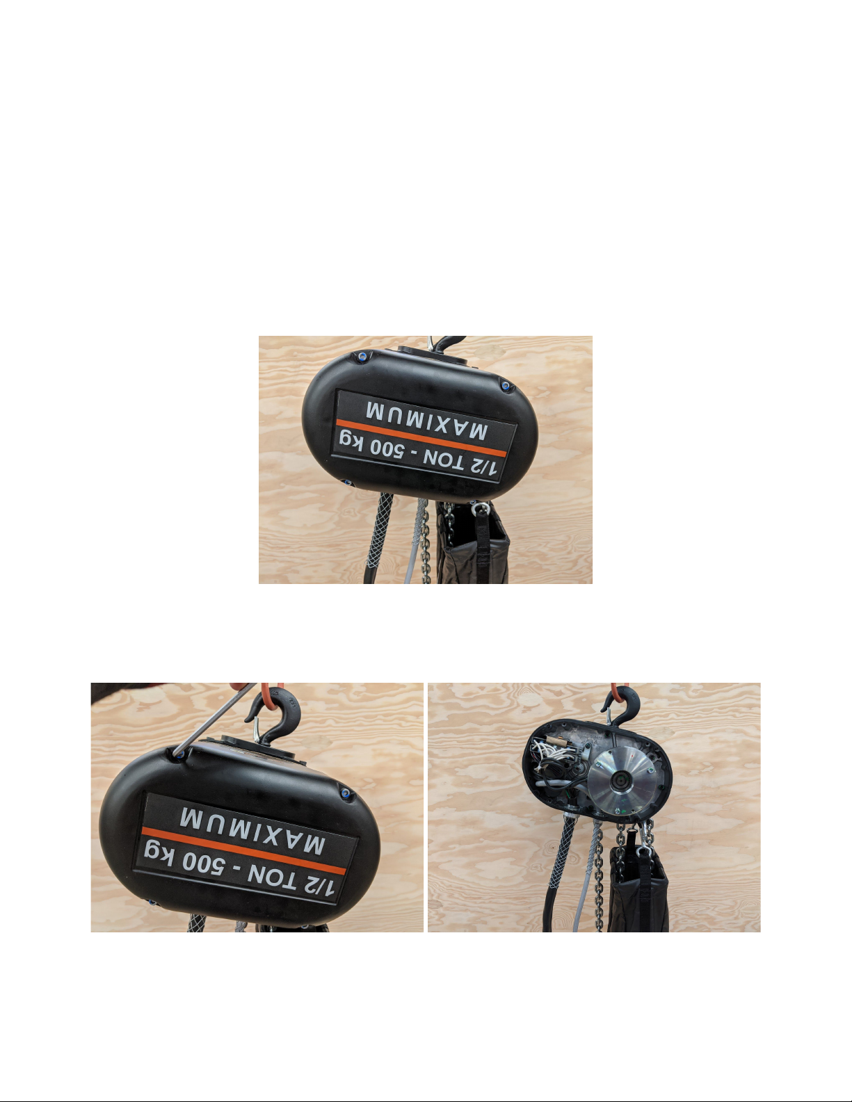
The Smart Chain Hoist can be installed motor up or motor down depending on your needs. Hanging
the machine motor up is most often best to reduce chain noise and the need for any cable
management.
In either orientation, it is important to confirm that the hook latch is fully closed and that the hanging
point is sufficient for the load prior to declaring victory. Be sure to employ safe rigging practices each
and every time a chain hoist is installed - the process should be completed by a competent and
qualified rigger.
Once the machine is safely and securely rigged, it's now time to think about connecting the scenery (or
any load) to the other hook. Be sure that the latch is fully closed and that the connecting point is
sufficiently stout to handle the load.
The Smart Chain Hoist is not rated for performer flying. Do not use the hoist to lift a performer, either
directly to the chain, on a prop, or on a piece of scenery.
Page 3

Smart Chain Hoist Reference Manual
Published 4-14-20
MAKING THE CONNECTIONS
The Smart Chain Hoist is nothing more than counterweight unless connected to a Stagehand Pro
controller. The Smart Chain Hoist will not function with any other Stagehand controller, nor any other
manufacturers’ controllers.
MOTOR/BRAKE
The motor and brake connections are made through a Harting or similar 24B locking connector. The
Smart Chain Hoist includes a latching hood to ensure the connection is maintained even under the
stresses of production use. Below is the pinout of the connector and cable.
SIGNAL
All encoder and limit signals are transmitted through the Signal cable with Harting or similar 6B locking
connectors. The Smart Chain Hoist includes a latching hood to ensure the signal connection is
maintained even under production conditions. Below, is the pinout of the signal connector.
Page 4

Smart Chain Hoist Reference Manual
Published 4-14-20
UNDER THE HOOD
Typically, you will not need to open your Smart Chain Hoist. However, you may need to adjust the
limits due to installation conditions, or you may need to access the terminal blocks for advanced
troubleshooting.
OPENING THE MACHINE
On each side of the hoist, there is a hood to protect the mechanics and electrical connections inside.
The limits are covered by the hood that has a label with the load rating of the machine and (4) SHCS.
These screws need to be loosened to take the limit enclosure hood off and access the inside of the
Smart Chain Hoist. To open the Smart Chain Hoist, you will need a 3/16” Allen key. Be aware, each
hood has a gasket which must be reseated properly.
Page 5

Smart Chain Hoist Reference Manual
Published 4-14-20
Inside the limit enclosure hood, you’ll find the Smart Chain Hoist’s rotatable limit switch and position
encoder, as well as its motor and load brakes.
The motor enclosure hood protects the motor, speed encoder, and most of its wiring. This hood is held
in place with (2) SHCS and has a label with the CM/Lodestar logo.
Like the limit enclosure, you will need to loosen the two screws with a 3/16” Allen Key. Once taken off,
you will see the motor and signal wiring, as well as the motor and speed encoder.
Page 6

Smart Chain Hoist Reference Manual
Published 4-14-20
There shouldn’t be a need to open this side of the hoist, however it’s always nice to know what you’re
looking at.
SETTING THE LIMITS
Setting limits is important for operating any automated effect. Setting limits prevents the machine from
moving past a safe location, protecting the machine and the load attached. The limits for the Smart
Chain Hoist are inside the enclosure and are pre-set from the factory to allow the maximum chain
travel while keeping the machine from damaging itself.
There may come a time when your installation requires resetting the limits for a particular installation.
Keep in mind that you will also need to restore those limits at the end of the run.
The Smart Chain Hoist includes four limits:
●FWD Ultimate
●FWD
●REV
●REV Ultimate
The initial and ultimate limits are factory set the correct distance apart to not inadvertently trip an
Ultimate Limit.
These limits are actuated by rotary discs on a threaded rod driven by a worm gear. The discs are
indexed for a capture plate to keep them from free spinning once the limit is set. As the motor runs, the
discs are pulled along the threaded rod until they make contact with the limit switch.
Page 7

Smart Chain Hoist Reference Manual
Published 4-14-20
To adjust the position of your rotary discs, you will need to loosen the two 5/32” SHCS that keep your
capture plate engaged with your discs.
Page 8

Smart Chain Hoist Reference Manual
Published 4-14-20
Once the screws have been loosened and the capture plate has been disengaged from the rotary
discs, you can freely spin the discs to your desired position to adjust where they will engage the limit
switches.
Once set, place the capture plate back into position, indexing with the rotary discs, and tighten the
5/32” screws. Once you test that the limits are engaging where you want them, you can replace your
limit hood onto the hoist enclosure.
It is also possible to move the initial limits closer or farther away from the ultimate limits, although we
don’t recommend doing so. The two initial limit plates are locked in place by (3) PHCS. The middle
screw locks both plates down, while each plate has an individual screw locking it down as well.
Page 9

Smart Chain Hoist Reference Manual
Published 4-14-20
When both screws on one plate are loosened, you can pivot the limit on an indexing pin, moving the
initial limit closer or farther away from the ultimate limit.
Page 10

Smart Chain Hoist Reference Manual
Published 4-14-20
POSITION SCALE
Each Smart Chain Hoist has its own position scale. This is a departure from most of our stock
machines and is due to small variances in each hoist. The Spikemark Machine Library has a stock
position scale, but to achieve the most accurate positioning you will need to set the position scale for
each Smart Chain Hoist. To ease this process, each machine has the Position Scale noted on a label,
directly above the electrical specs.
This number will need to be set in the Position Scale field in Spikemark. If you are having trouble with
the scaling on your Smart Chain Hoist, you can calculate and adjust either by using our Position Scale
Wizard or by calculating the math yourself.
Page 11

Smart Chain Hoist Reference Manual
Published 4-14-20
To adjust your scaling, bring the Smart Chain Hoist’s hoisting hook down to where you want your
“zero” point to be. Bring up the Position Scale Wizard, reset your zero, and run the hoisting hook to
your maximum allowable height. Measure the distance from zero to this height and input that number
into the position wizard and it will calculate the position scale for you. If you do not want to use the
Wizard, you can calculate your position scaling with the formula shown below.
Page 12

Smart Chain Hoist Reference Manual
Published 4-14-20
BRAKE TESTING
The Stagehand Pro can control two brakes for use in hoisting applications. The Stagehand Pro will
internally check the electronic systems to ensure the brake circuits are working properly before
releasing either the motor brake or the load brake to prevent dropping a suspended piece of scenery.
However, the Stagehand cannot confirm that the brakes are mechanically operating correctly.
Since the Stagehand cannot confirm that both brakes are functioning mechanically and that neither
has jammed in a released state (very rare, but possible), the brakes should be tested at every install
and nightly pre-show check. The Stagehand has convenient buttons on the faceplate to assist you with
testing the brakes. To test that your brakes are operating correctly on your Smart Chain Hoist, read
through the following steps in their entirety and then perform each action as follows:
●Clear the stage below the suspended scenery
●Press the Brake Test button
●While holding the Brake Test Button, press the Load Brake button. This will manually release the
Load Brake. The Motor Brake should still be engaged and will hold the load. If the suspended
scenery slips down, release the Load Brake button immediately. Since the Motor Brake did not
hold the load as expected, that brake has failed. DO NOT OPERATE THE MACHINE UNTIL THE
MOTOR BRAKE IS REPAIRED OR REPLACED. FAILURE TO REMOVE THE MACHINE FROM
SERVICE COULD RESULT IN DAMAGE, INJURY, OR DEATH.
Page 13

Smart Chain Hoist Reference Manual
Published 4-14-20
●Provided the Motor Brake passed the functional test, release the Load Brake button.
●While holding the Brake Test Button, press the Motor Brake button. This will manually release
the Motor Brake. The Load Brake should still be engaged and will hold the load. If the
suspended scenery slips down, release the Motor Brake button immediately. Since the Load
Brake did not hold the load as expected, that brake has failed. DO NOT OPERATE THE
MACHINE UNTIL THE LOAD BRAKE IS REPAIRED OR REPLACED. FAILURE TO REMOVE THE
MACHINE FROM SERVICE COULD RESULT IN DAMAGE, INJURY, OR DEATH.
Page 14

Smart Chain Hoist Reference Manual
Published 4-14-20
●Release the Motor Brake button
Pro Tip: If you press all three buttons at once, all brakes will engage
For use with the Smart Chain Hoist, we suggest that this procedure be executed every night to ensure
that all equipment is operating in a safe, reliable manner.
Page 15

Smart Chain Hoist Reference Manual
Published 4-14-20
VFD SETTINGS
The parameter settings on the Mitsubishi Variable Frequency Drive (VFD) are tailored to make the unit
work effectively with each machine. The Smart Chain Hoist uses a different set of VFD parameters
than all of the other Creative Conners, Inc. stock products. Below is a list of the parameters that are
changed from the factory defaults, and what they do. Viewing and changing the parameters is a
straightforward process. On the VFD keypad press the MODE button until a ‘P’ is displayed. Use the
wheel to scroll to the desired parameter number and press the SET button. The display will change
and display a number value. Use the wheel to adjust the value and press SET. To make no change,
simply press the SET button. When all settings are confirmed/adjusted, press the mode button 3 times
until the display shows 0.00. A more detailed explanation of this process can be found at
http://cci.fyi/vfd.
We have designed a few variants of the Stagehand Pro and they each need slightly different
parameters to run your Smart Chain Hoist efficiently and effectively. To know what Stagehand Pro
and VFD you have, look at the VFD keypad on the face plate and notice where that keypad is located
on the Stagehand itself. If the keypad is square and is located on the bottom right of the faceplate, it is
a Stagehand Pro 3 with an A800. If the keypad is square on the bottom left of the faceplate it is a
Stagehand Pro 2 with an A800. If it is rectangular and is located on the bottom left of the faceplate, it
is a Stagehand Pro 2 with an A700.
YOU MUST SET PARAMETER 77 = 2 PRIOR TO BEGINNING THE MANUAL RESTORE
PROCESS
Pr.
No.
Name
Description
Stagehand
Pro 3
Stagehand
Pro 2 A800
Stagehand
Pro 2 A700
1
Maximum frequency
Set the upper limit of the output
frequency.
110
110
110
2
Minimum frequency
Set the lower limit of the output
frequency.
0
0
0
3
Base frequency
Set the frequency at the rated
motor torque. (50Hz/60Hz)
106
106
106
7
Acceleration time
Standard time to accelerate a
movement.
0
0
0
8
Deceleration time
Standard time to decelerate a
movement.
0
0
0
9
Electronic thermal O/L relay
Current rating from the motor
nameplate.
13
13
13
10
DC injection brake operation
Set the frequency at which the
0.5
0.5
0.5
Page 16
Table of contents
Popular Chain Hoist manuals by other brands

pela tools
pela tools PA200 manual

KITO
KITO RY Series Disassembly and Reassembly

Surewerx
Surewerx JET MINI-MITE II Series Operator's manual

Feider Machines
Feider Machines F2TPA-A instruction manual

Liftket
Liftket STAR LIFTKET VFD Operating Instructions Supplementary Sheet

Columbus McKinnon
Columbus McKinnon Coffing JLC Series Operating, Maintenance & Parts Manual