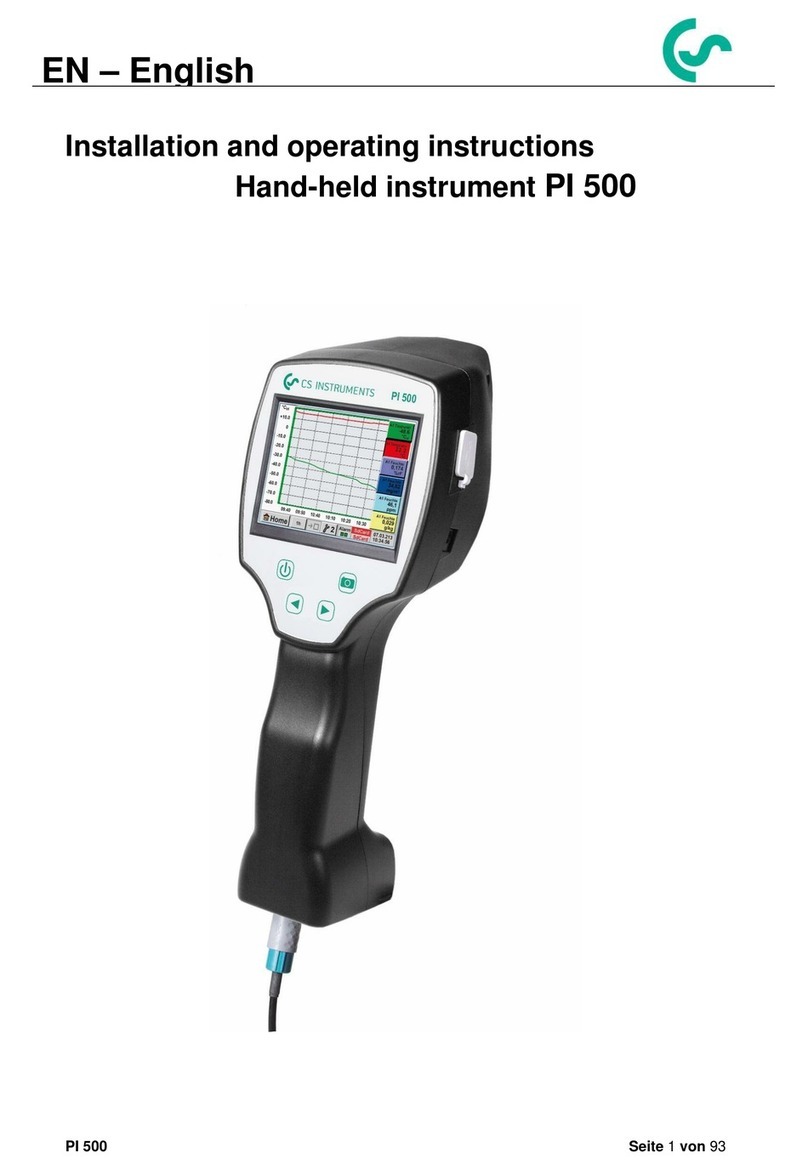
CS Instruments DP 510 User manual

DP 500 / DP 510 V1.33 Seite 1von 96
Installation and operating instructions
portable dew point meters
DP 500 / DP 510
EN –English

Foreword
DP 500 / DP 510 V1.33 Seite 2von 96
I. Foreword
Dear customer,
thank you very much for deciding in favour of the DP 500 / DP 510. Please read this
installation and operation manual carefully before mounting and initiating the device
and follow our advice. A riskless operation and a correct functioning of the DP 500 /
DP 510 are only guaranteed in case of careful observation of the described
instructions and notes
Sales Office South / Geschäftsstelle Süd
Zindelsteiner Str. 15
D-78052 VS-Tannheim
Tel.: +49 (0) 7705 978 99 0
Fax: +49 (0) 7705 978 99 20
Web: http://www.cs-instruments.com
Sales Office North / Geschäftsstelle Nord
Gewerbehof 14
D-24955 Harrislee
Tel.: +49 (0) 461 807 150 0
Fax: +49 (0) 461 807 150 15
Web: http://www.cs-instruments.com

Table of Contents
DP 500 / DP 510 V1.33 Seite 3von 96
II. Table of Contents
1SAFETY INSTRUCTIONS 6
2ENVIRONMENTAL PROTECTION 7
3APPLICATION AREA 8
4TECHNICAL DATA DP 500 / DP 510 9
5INSTALLATION AND MEASUREMENTS 10
5.1 Measurement with measuring chamber, connection via plug nipple 10
5.2 Measurement without measuring chamber, connection via external thread G1/2’’ 10
5.3 Dew point measuring at synthetic granules -dries 11
6MAINTENANCE 11
7CALIBRATION / ADJUSTMENT 11
8INPUTSIGNALS EXT. SENSOR DP 510 12
9CABLE CROSS SECTION 12
9.1 Sensor circuit points/Output signal: 12
10 CONNECTION DIAGRAMS OF THE DIFFERENT SENSOR TYPS (DP 510 ONLY)
13
10.1 Connector pin assignment for all sensors DP 510 13
10.2 Connection CS dew point sensors series FA 415/FA 300 14
10.3 Connection for CS dew point- and consumption sensors, series FA/VA 400 14
10.4 Connection for CS dew point- and consumption sensors, series FA/VA 5xx 14
10.5 Connection pulse sensors 15
10.6 Analogue two-, three-, and four-wire current signal 16
10.7 Three- and four-wire power supply 0 - 1/10/30 VDC 17
10.8 Two-, three-, and four-wire connector pin assignments for PT100/PT1000/KTY81 18
10.9 Connection with RS485 18

Table of Contents
DP500 / DP 510 1.33 Seite 4von 96
11 OPERATION DP 500 / DP 510 19
11.1 Keypad 19
11.1.1 On- and Off button 19
11.1.2 Brightness buttons 19
11.1.3 Screenshot-Button 19
11.1.3.1 Storing Screenshot 19
11.1.3.2 Export Screenshots 20
11.2 Touchpanel 22
11.3 Main menu (Home) 23
11.3.1 Initialization 23
11.3.2 Main menu 24
11.3.2.1 Settings 25
11.3.2.1.1 Password-Settings 25
11.3.2.1.2 Sensor-settings 26
11.3.2.1.2.1 Settings internal Dew point-Sensor 27
11.3.2.1.2.1.1 Definition of the System pressure (relative pressure value) 27
11.3.2.1.2.1.2 Definition of Reference pressure (absolute pressure value) 28
11.3.2.1.2.2 Choice of the sensor type (For example type CS-Digital sensor) 29
11.3.2.1.2.3 Label and setting the description fields 29
11.3.2.1.2.4 Name the measurement data and define the decimal places 30
11.3.2.1.2.5 Recording measurement data 30
11.3.2.1.2.6 Alarm-Settings ( Alarm Popup) 31
11.3.2.1.2.7 More Settings (scale analogue output) 32
11.3.2.2 Dew Point Sensor FA 400 / FA 410 of type CS-Digital (SDI Bus) 33
11.3.2.3 Flow sensor VA 400 / VA 420 of type CS-Digital (SDI Bus) 34
11.3.2.4 Dew Point Sensor FA 500 / FA 510 of type FA 5xx (RS 485 Modbus) 37
11.3.2.4.1 Settings Dew point sensor FA 500 FA 510 38
11.3.2.4.1.1 Unit selection for temperature and humidity 38
11.3.2.4.1.2 Definition of the System pressure (relative pressure value) 38
11.3.2.4.1.3 Definition of Reference pressure (absolute pressure value) 39
11.3.2.4.2 Calibration 39
11.3.2.4.3 More Settings Analogue output 4-20mA 40
11.3.2.5 Flow sensor of type VA 5xx (RS 485 Modbus) 41
11.3.2.5.1 Settings for Flow sensor VA 5xx 42
11.3.2.5.1.1 Diameter settings 42
11.3.2.5.1.2 Gas Constant settings 43
11.3.2.5.1.3 Definition of the reference conditions 44
11.3.2.5.1.4 Definition Unit of flow and velocity 44
11.3.2.5.1.5 Definition consumption counter value and consumption unit 44
11.3.2.5.2 Settings analogue output 4-20mA of VA 5xx 46
11.3.2.5.3 Settings Pulse / Alarm output of VA 5xx 47
11.3.2.5.4 Settings ZeroPoint or Low Flow Cut off for VA 5xx 48
11.3.2.5.4.1 Configuration of Analog-Sensors 49
11.3.2.5.4.2 Type 0 - 1/10/30 Volt and 0/4 –20 mA 49
11.3.2.5.4.3 Type PT100x and KTY81 51
11.3.2.5.4.4 Type Pulse (Pulse ration) 52
11.3.2.5.4.5 Type „No Sensor“ 54
11.3.2.5.4.6 Type Modbus 55
11.3.2.5.4.7 Selection and activation of Sensor-Type Modbus 55
11.3.2.5.4.7.1 Modbus Settings 55
11.3.2.5.5 Data logger Settings 59
11.3.2.5.6 Device Settings 63
11.3.2.5.6.1 Language 63
11.3.2.5.6.2 Date & Time 64
11.3.2.5.6.3 SD-Card 65
11.3.2.5.6.4 System update 66

Table of Contents
DP500 / DP 510 1.33 Seite 5von 96
11.3.2.5.6.4.1 Save System Settings 66
11.3.2.5.6.4.2 Check for new Software updates (USB) 67
11.3.2.5.6.5 Factory Reset 68
11.3.2.5.6.6 Calibrate touch-screen 69
11.3.2.5.7 Cleaning 69
11.3.2.5.8 System-Status 69
11.3.2.5.9 About DP 500 / DP 510 70
11.3.2.6 Chart 71
11.3.2.7 Chart / Real time values 75
11.3.2.8 Channels 77
11.3.2.8.1 Min/Max Function 77
11.3.2.9 Real time values 79
11.3.2.10 Alarm overview 80
12 VIRTUAL CHANNELS (OPTIONAL) 81
12.1 Option „Virtual Channels“ activation 81
12.2 Virtual Channels Settings 82
12.2.1 Selection of Sensor-type 82
12.2.2 Configuration of each single virtual value 83
12.2.3 Activation of a single virtual value 83
12.2.4 Definition of Operands 83
12.2.5 Definition of Operations 85
12.2.6 Definition of Unit 85
12.2.7 Value name, resolution of decimal places and recording of values 87
13 ANALOG TOTAL (OPTIONAL ONLY FOR DP 510) 88
13.1 Option „Analog Total“ activation 88
13.2 Selection of sensor type 89
14 EXPORT /IMPORT 90
14.1 Export Logger data 90
14.2 Export System Settings 92
14.3 Import System Settings 93

Safety instructions
DP 500 / DP 510 V1.33 Seite 6von 96
1 Safety instructions
Please check whether this manual corresponds with the device type.
Please attend to all notes indicated in this instruction manual. It contains essential information
which has to be followed during installation, operation and maintenance. Therefore, this
instruction manual has to be read categorically by the technician as well as by the responsible
user/qualified personnel before installation, initiation and maintenance.
This instruction manual has to be available at any time at the operation site of the DP 500 / DP
510. Regional and national regulations respectively, have to be observed in addition to this
instruction manual if necessary.
In case of any obscurities or questions with regard to this manual or the instrument please contact
CS Instruments GmbH.
Warning!
Supply voltage!
Contact with supply voltage carrying non-insulated parts may cause an electric shock
with injury and death.
Measures:
•Note all applicable regulations for electrical installations (e.g. VDE 0100)!
•Carry out maintenance only in strain less state!
•All electric works are only allowed to be carried out by authorized qualified personnel.
Warning!
Inadmissible operating parameters!
Undercutting and exceeding respectively of limit values may cause danger to persons
and material and may lead to functional and operational disturbances.
Measures:
•Make sure that the DP 500 / DP 510 is only operated within the admissible limit values indicated
on the type label.
•Strict observance of the performance data of the DP 500 / DP 510 in connection with the application.
•Do not exceed the admissible storage and transportation temperature.
Further safety instructions:
•Attention should also be paid to the applicable national regulations and safety instructions during
installation and operation.
•The DP 500 / DP 510 is not allowed to be used in explosive areas.
Additional remarks:
•Do not overheat the instrument!
•In case of mounting by screwing please use spanner flat (SW27)!
•DP 500 / DP 510 is not allowed to be disassembled!
Attention!
Malfunctions at the DP 500 / DP 510!
Faulty installation and insufficient maintenance may lead to malfunctions of the DP 500 /
DP 510 which may affect the measuring results and which may lead to misinterpretations.

Environmental protection
DP 500 / DP 510 V1.33 Seite 7von 96
2 Environmental protection
•Disposal of defective batteries / dead batteries according to the valid legal
regulations.
•After the end of the useful life, take the product to the separate collection for
electrical and electronic equipment (observe local regulations) or return the product
to CS Instruments GmbH & Co.KG for disposal.
CS Instruments GmbH & Co.KG makes no warranty as to its suitability for any particular purpose
and assumes no liability for any errors contained in this manual. Nor for consequential damages in
connection with the delivery, performance or use of this device.
The following accumulator is contained in this electrical appliance
Battery type
Chemical system
Akkumulator
LiIon 2S1P
Information on the safe removal of the batteries or accumulators
•Warning: Make sure that the battery is completely empty.
•Removing the battery
Removing the battery cover Disconnecting the connector Carefully pull out the battery
•Carefully remove the accumulator
•The accumulator and the appliance can now be disposed of separately

Environmental protection
DP 500 / DP 510 V1.33 Seite 8von 96
3 Application Area
The new instruments DP 500/DP510 are the ideal portable service instruments for dew point
measurement for all types of driers down to -80°Ctd dew point
The 3.5” graphic display with touch screen makes the operation very easy.
The graphic indication of coloured measuring curves is unique.
Ideal for measurement of the current dew point and for graphic indication of the dew point curve/the
switching behaviour of the drier over a longer period of time.
Up to 100 million measured valued can be stored with date and measuring site name. The measured
data can be transferred to the computer via USB stick.
DP 510 additionally disposes of one further freely assignable sensor input.
Apart from the internal dew point measurement, one further optional sensor can be connected like for
example:
•Pressure sensors
•Flow sensors, VA 400/420
•Temperature sensors Pt 100, 4..20 mA
•Further dew point sensors
•Effective power meters
•Optional third-party sensors with the following signals:
0...1/10 V, 0/4...20 mA, Pt100, Pt1000, pulse, Modbus
Application ranges:
•Compressed air: Examination of refrigeration,
membrane, adsorption driers
•Technical gases: Residual moisture measurement
in gases like N2, O2 and so on
•Plastics industry: Examination of
granulate driers
•Medical compressed air/breathing air

Technical data
DP 500 / DP 510 V1.33 Seite 9von 96
4 Technical data DP 500 / DP 510
Colour screen
3.5“-Touchpanel TFT transmissive, graphics, curves, statistics
Interfaces
USB
Measuring ranges
-80…+50 °Ctd
-20…+70 °C
0…100 % rF
Accuracy
± 0,5 °Ctd (-10…+50 °Ctd)
typical:. ± 2 °Ctd
Humidity measures
g/m³, mg/m³, ppm V/V, g/kg, °Ctdatm, % rF
Response Time T95
-50°Ctd ---- -10°Ctd < 10sec
-10°Ctd ---- -50°Ctd < 5 minutes
Pressure range
Mounting without measuring chamber: -1…50 bar Standard
Mounting with measuring chamber: : 2…16 bar
High pressure version up to 350 bar
Power supply for sensors
(only DP510)
Output voltage: 24 VDC ± 10%
Output current: 120 mA continuous operation
Current supply
Internal rechargeable Li-Ion batteries charging time approx. 4 h
DP 500 operation: approx. 12h,
DP 510 operation: > 4h depending on current consumption of external sensor
Power supply unit
100 –240 VAC/50 –60 Hz, 12VDC –1A
Safety class 2, only for application in dry rooms
Dimensions
125 x 96 x 245 mm
Material
Plastic PC/ABS
Weight
550 g
Operating temperature
-20...70°C measuring gas temperature
0... 50°C ambient temperature
Storage temperature
-20 to +70°C
Optional
Data Logger, Memory size 8 GB SD memory card standard
EMC
DIN EN 61326

Installation , Measurements and maintenance
DP 500 / DP 510 V1.33 Seite 10 von 96
5 Installation and measurements
We recommend the use of a measuring chamber!
5.1 Measurement with measuring chamber, connection via plug nipple
5.2 Measurement without measuring chamber, connection via external thread G1/2’’
1. Preparation of the measuring point
Let compressed air flow off at the sampling point before
measurement in order to remove condensate and particles.
This avoids a soiling of DP 500 / DP 510 and the measuring
chamber.
Stagnant air leads to long adjustment times.
If condensate occurs at the measuring point, please check the
compressed-air conditioning before measurement.
2. Switch on DP 500 / DP 510 and wait until the initialization
has been finished.
Please observe the chapter "Operation".
3. Connect the measuring chamber screwed onto DP 500 / DP
510 with the plug nipple coupling of the measuring point
4. Wait until the value in the display of DP 500 / DP 510 has
stabilized. Depending on the position of the measuring point
this may take up to 15 minutes*.
*If the DP has been used in a system with a higher dew point
for a longer period of time or has been stored in ambient air, a
longer period of time is required, especially for low dew points.
5. Disconnect the measuring chamber from the plug nipple
coupling of the measuring point after measurement. Switch off
DP 500 / DP 510 if you do not want to carry out further
measurements.
1. Preparation of the measuring point
Make sure that the measuring point is depressurized.
Please check the sampling point before measurement.
If condensate occurs at the measuring point you should check
the compressed-air conditioning before measurement.
2. Screw the DP 500 / DP 510 (without mounted measuring
chamber) into the measuring point (with internal thread G1/2“).
For mounting you should use the spanner flat (SW27)!
3. Switch on DP 500 / DP 510 and wait until the initialization
has been finished.
Please observe the chapter "Operation".
4. Charge the measuring point slowly with pressure.
5. Wait until the value in the display of DP 500 / DP 510 has
stabilized. Depending on the position of the measuring point
this may take up to 15 minutes*.
*If the DP has been used in a system with a higher dew point
for a longer period of time or has been stored in ambient air, a
longer period of time is required, especially for low dew points.
6. After measurement please drain the pressure slowly from the
measuring point.
7. Remove DP 500 / DP 510 from the measuring point. For
demounting the instrument, you should use the spanner flat
(SW 27)!
8. If you do not want to carry out further measurements please
switch off DP 500 / DP 510.

Einbau , Messungen und Wartung
DP500 / DP 510 1.33 Seite 11 von 96
5.3 Dew point measuring at synthetic granules -dries
6 Maintenance
Cleaning of the sensor
The sensor can be cleaned by careful swinging in distilled water or isopropanol.
Remark:
Do not touch the surface of the sensor pad.
Avoid mechanical impact to the sensor (e.g. by means of a sponge or a brush).
If the sensor is much polluted the only possibility will be an examination and maintenance by the
manufacturer.
7 Calibration / Adjustment
We recommend an annual calibration and if necessary adjustment of the measuring instrument at the
manufacturer.
Please observe the enclosed inspection certificate.
Synthetic granules-dries usually work with a slight positive
pressure in the millibar range. Use in this application, with a
slight excess pressure, the measuring chamber for synthetic
granules dryer (Order No. 0699.3490).
Since the air temperature in the synthetic granules dryer is also
very high, the air supply from the synthetic granules dryer to the
measuring chamber via a correspondingly long Teflon tube
(recommended length of 1-2 m), which serves as a cooling
section. Note that the measured air temperature in the DP 500
if possible remains below 40 ° C, otherwise please use a longer
Teflon tube as a cooling section.
The supply of air into the measuring chamber via port A (air
input). On the air output, a Teflon tube is connected with a
length of at least 80 cm. This prevents the back flow of humid
ambient air back into the measuring chamber.
Air input
Air output

Inputsignals for ext. Sensor DP 510
DP 500 / DP 510 V1.33 Seite 12 von 96
8 Inputsignals ext. sensor DP 510
9 Cable cross section
9.1 Sensor circuit points/Output signal:
AWG16 –AWG28, cable cross-sections: 0,14 - 1,5 mm2
Input signals
Current signal
(0 –20 mA / 4 –20 mA)
internal or external
power supply
Measuring range
0 –20 mA / 4 –20 mA
Resolution
0,0001 mA
Accuracy
0,03 mA 0,05 %
Input resistance
50
Voltage signal
(0 - 1V)
Measuring range
0 - 1 V
Resolution
0,05 mV
Accuracy
0,2 mV 0,05 %
Input resistance
100 k
Voltage signal
(0 - 10 V / 30 V)
Measuring range
0 - 10 V/30 V
Resolution
0,5 mV
Accuracy
2 mV 0,05 %
Input resistance
1 M
RTD
Pt100
Measuring range
-200 - 850 °C
Resolution
0,1 °C
Accuracy
0,2 °C at -100 - 400 °C
0,3 °C (further range)
RTD
Pt1000
Measuring range
-200 - 850 °C
Resolution
0,1 °C
Accuracy
0,2 °C at -100 - 400 °C
0,3 °C ( further range )
Pulse
Measuring range
minimal pulse length 100
μ
s
frequency 0 - 1 kHz
max. 30 VDC

Connection diagrams of the different sensor types (DP 510 only)
DP 500 / DP 510 V1.33 Seite 13 von 96
10 Connection diagrams of the different sensor typs (DP 510 only)
10.1 Connector pin assignment for all sensors DP 510
The interface connector to be used is an ODU Medi Snap 8 pin –Reference: K11M07-P08LFD0-6550
.
Available connection cables at CS-Instruments are:
ODU with Open ends: Order no 0553 0501, cable length: 5 m.
Order no 0553 0502, cable length: 10 m.
ODU with M12 Connector: Order no 0553 0503, cable length: 5 m.
Extension cable (ODU/ODU): Order no 0553 0504, cable length: 10 m.
Connection scheme:
Connector housing
Plug insert
Collet
Clamping nut
View on welding pins of Medi Snap Connector
Cable lenght 5m/10 m
1weiss white
2braun brown
3grün green
4gelb yellow
5grau grey
6rosa pink
7blau blue
8rot red
I (500µA)
12345678
+ RS485
- RS485
SDI
Analog IN +
+VB 24Vdc
-VB GND
Analog IN -
+ RS485
- RS485
SDI (CS-internal Single wire Digital Interface for all dew point / Flow sensors)
ANALOG IN +
ANALOG IN –
STROMQUELLE 500 µA
+VB, 24V DC Power supply for sensor
-VB, GND Sensor
S11M07-P08MFD0-6550
1 8
2 7
3
6
4
5
White
Brown
Green
Yellow
Grey
Pink
Blue
Red

Connection diagrams of the different sensor types (DP 510 only)
DP500 / DP 510 1.33 Seite 14 von 96
FA serial: dew point sensors from CS Instruments
VA serial: consumption sensors from CS Instruments
10.2 Connection CS dew point sensors series FA 415/FA 300
1
3 2
SDI
+-
Sensor
I (500µA)
12345678
+ RS485
- RS485
SDI
Analog IN +
+VB 24Vdc
-VB GND
Analog IN -
DP510
FA 300
FA 415
The digital data transmission between DP 510 and the dew point
sensors FA 415 and FA 300 occur via the SDI bus line.
10.3 Connection for CS dew point- and consumption sensors, series FA/VA 400
1
3 2
SDI
+-
I (500µA)
12345678
+ RS485
- RS485
SDI
Analog IN +
+VB 24Vdc
-VB GND
Analog IN -
DP510
FA 410
FA 400
VA 400
VA 420
The digital data transmission between DP 510 and the sensors FA
400/410 and VA 400/420 occurs via the SDI bus line.
.
10.4 Connection for CS dew point- and consumption sensors, series FA/VA 5xx
2
1 3
Sensor
+-
I (500µA)
12345678
+ RS485
- RS485
SDI
Analog IN +
+VB 24Vdc
-VB GND
Analog IN -
4
DP510
FA 510
FA 500
VA 500
VA 520
The digital data transmission between DP 510 and the sensors
FA 500/ FA 510 and VA 500/520 occurs via RS 485 (Modbus).
green
blue
red
blue
red
green
Blue
Red
White
Brown

Connection diagrams of the different sensor types (DP 510 only)
DP500 / DP 510 1.33 Seite 15 von 96
10.5 Connection pulse sensors
I (500µA)
12345678
+ RS485
- RS485
SDI
Analog IN +
+VB 24Vdc
-VB GND
Analog IN -
+
1 = 2.5V –30V
0 = 0V –0.7V
-
Signal level 0:
low = 0 –0,7 VDC
Signal level 1:
high = 2,5 –30 VDC
t = 400 µs
max. frequency
(duty cycle 1:1) = 1000 Hz
input resistance:
min. 100 kilo ohm
I (500µA)
12345678
+ RS485
- RS485
SDI
Analog IN +
+VB 24Vdc
-VB GND
Analog IN -
R
Required external
R = 4K7
Attention:
The DP 510 is counting a
consumption unit, by switching
„power on“.
I (500µA)
12345678
+ RS485
- RS485
SDI
Analog IN +
+VB 24Vdc
-VB GND
Analog IN -
R
Required external
R = 4K7
I (500µA)
12345678
+ RS485
- RS485
SDI
Analog IN +
+VB 24Vdc
-VB GND
Analog IN -
Not possible / allowed!
yellow
grey
yellow
grey
blue
blue
red
red
yellow
grey
yellow
grey

Connection diagrams of the different sensor types (DP 510 only)
DP500 / DP 510 1.33 Seite 16 von 96
10.6 Analogue two-, three-, and four-wire current signal
Sensors with 4 - 20 mA-output in 2-wire technology
I (500µA)
12345678
+ RS485
- RS485
SDI
Analog IN +
+VB 24Vdc
-VB GND
Analog IN -
+
Sensor
ß0 / 4 ...20mA
DP510
Sensors with 4 - 20 mA output in 3-wire technology
I (500µA)
12345678
+ RS485
- RS485
SDI
Analog IN +
+VB 24Vdc
-VB GND
Analog IN -
+-
Sensor
ß0 / 4 ...20mA
.
DP510
Sensors with 4 - 20 mA output in 4-wire technology
à0 / 4 ...20mA
ß0 / 4 ...20mA
I (500µA)
12345678
+ RS485
- RS485
SDI
Analog IN +
+VB 24Vdc
-VB GND
Analog IN - Sensor
+-
DP510
Yellow
Yellow
Yellow
Grau
blue
blue
blue
red
red

Connection diagrams of the different sensor types (DP 510 only)
DP500 / DP 510 1.33 Seite 17 von 96
10.7 Three- and four-wire power supply 0 - 1/10/30 VDC
+-
ß0...1 / 10 / 30 Vdc +
I (500µA)
12345678
+ RS485
- RS485
SDI
Analog IN +
+VB 24Vdc
-VB GND
Analog IN - Sensor
Yellow
Blue
red
Bridge
Sensor with voltage output in 3-wire technology
+
-
ß0...1 / 10 / 30 Vdc
I (500µA)
12345678
+ RS485
- RS485
SDI
Analog IN +
+VB 24Vdc
-VB GND
Analog IN - Sensor
+-
Sensor with voltage output in 4-wire technology
Yellow
grey
blue
red

Connection diagrams of the different sensor types (DP 510 only)
DP 500 / DP 510 V1.33 Seite 18 von 96
10.8 Two-, three-, and four-wire connector pin assignments for PT100/PT1000/KTY81
Yellow
rd
pink
Sensor
I (500µA)
12345678
+ RS485
- RS485
SDI
Analog IN +
+VB 24Vdc
-VB GND
Analog IN -
2-wire PT100/PT1000/KTY81
Sensor
I (500µA)
12345678
+ RS485
- RS485
SDI
Analog IN +
+VB 24Vdc
-VB GND
Analog IN -
3-wire PT100/PT1000/KTY81
Sensor
I (500µA)
12345678
+ RS485
- RS485
SDI
Analog IN +
+VB 24Vdc
-VB GND
Analog IN -
4-wire PT100/1000/KTY81
10.9 Connection with RS485
I (500µA)
12345678
+ RS485
- RS485
SDI
Analog IN +
+VB 24Vdc
-VB GND
Analog IN -
+
-
Sensor
+-
Sensor with RS485 interface
Yellow
Yellow
grey
grey
Pink
Pink
red
red
blue
white
brown
red

Operation DP 500 / DP 510
DP 500 / DP 510 V1.33 Seite 19 von 96
11 Operation DP 500 / DP 510
The operation of the DP 500 / DP 510 by means of a keypad and a touch panel
11.1 Keypad
11.1.1 On- and Off button
On-or Off switching by long press buttons.
11.1.2 Brightness buttons
With the button and the display brightness can be changed.
11.1.3 Screenshot-Button
By pressing the Screenshot-button, the actual display content will be stored.
Storage is possible either to a USB Stick or on to the internal SD-card
11.1.3.1 Storing Screenshot
After pressing the Screenshot button a menu (see
left) appears where the storage target, USB Stick or
internal SD-card, could be selected.
The screens are stored as bitmap and the naming is
a consecutively number. For new every day a new
folder is created.
Folder definition; DJJMMTT
D=fix(for date)
JJ = year
MM= month
TT= day
Path: DEV0003/DP500/Bitmap
Example: first picture 10. September 2013
\\DEV0003/P500/Bitmap/D130910/B00000.bmp

Operation DP 500 / DP 510 - Touchpanel
DP500 / DP 510 1.33 Seite 20 von 96
11.1.3.2 Export Screenshots
The stored bitmaps on the SD-card could be exported to a USB –Stick.
Main menu ➔Export/Import➔Export Screenshots
Main menu ➔Export Data ➔Export Screenshots
Main menu ➔Export Data ➔Export Screenshots➔Change
With Export Screenshots the stored
Screenshots will be transferred to a USB-
Stick.
Use the Change buttons to adjust a period
between start and end. Stored bitmaps data in
this period are exported.
The selected date is always green, and the
date numbers of the Sundays are red, like in
the calendar.
On days, where bitmaps were recorded, the
date numbers are optical highlighted.
This manual suits for next models
2
Table of contents
Other CS Instruments Handheld manuals
