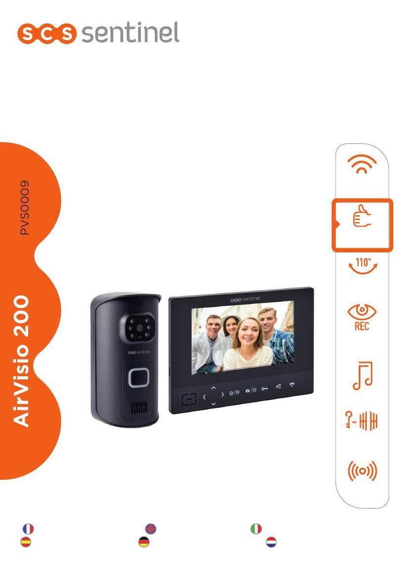
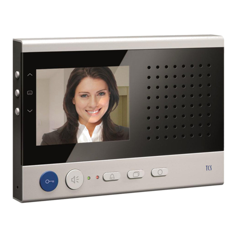
CSD Electronic Peephole Viewer Technical specifications

Electronic peephole viewer
Product description
Contents
Part I: Product description.......................................................................................... 2
1. Product main features, functions...................................................................... 2
2. Product appearance..........................................................................................2
3. Package contents..............................................................................................4
Part II: Installation Instructions...................................................................................5
Part III: Product Notes & FAQ................................................................................... 5

Part I: Product description
1. Product main features, functions
Electronic peephole viewer is a new kind of home security product. It is different from the
traditional glass peephole. With the LCD screen set up inside your home to observe the visitors, it
is safer and more beautiful. To set up the item on your door, no construction is needed and there is
no damage to your door. Just use the electronic peephole viewer to replace your traditional glass
one. It is also easy to install the electronic peephole viewer on the door without glass peephole on
it. The electronic peephole viewer can totally replace the the traditional glass peephole.
Fashion appearance, ultra-thin design, perfectly melt into modern home life
Wide-angle, high definition, high brightness screen, very clear image of the visitor
Prevent from reverse peeping, protect your privacy
Strong night vision function, able to be used at night
Our new destruction alarm function
Advanced power management and energy-saving technology
Automatically take photos and restore the photos when the visitors ring the doorbell, easy to check
the record and able to upload the photos to your computer
Internal 2G Micro-SD(TF) memory card
Main functions:
Model T1: 2.8 Inch Screen Ultra High Definition Electronic Peephole Viewer with Photographing
1) Display the visitor on the LCD screen
2)300 thousand pixels camera
3) Internal 2G Micro-SD(TF) memory card
4) Night vision
5) Photographing
6) Destruction alarm
Model: T1
Product Specifications:
Name Shape, Parameter
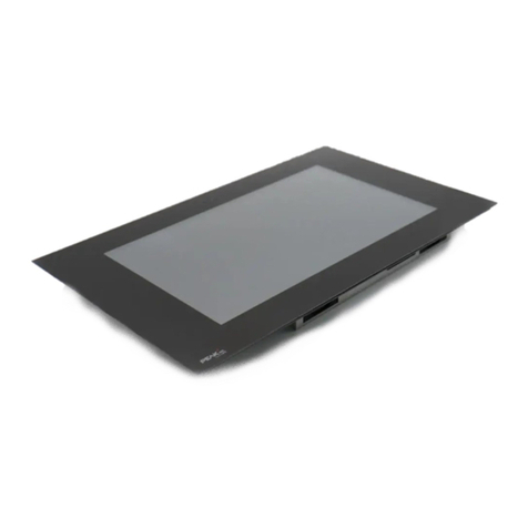
Indoor Device Shape size: L109×W96mm
LCD Screen size: 2.8"
Outdoor Device Shape size: Φ54mm
Camera: 300 thousand pixels camera
Installation Dimensions Door Thickness: 35mm~105mm
Installation Hole Diameter: 18mm~50mm

Key Description:
The Outdoor Device Operating Instructions:
Visitors Calling: Press the button on the outdoor unit, then the indoor device will ring and display
the visitor's image, take a photo and restore it.
The Indoor Device Operating Instructions:
1) Monitoring: Press the "power" button. Then the indoor device starts to operate, automatically
take a photo of the outdoor situation and restore it. Now you can observe the outdoor situation
displayed on the screen. To switch off the indoor device, press the "power" button again.
2) Browse and Delete the Photos
1. Browse Photos:
To switch to the browse mode, press the "up" button (or "down" button) under the Monitoring
Mode. Then, you can press the "up" button to browse the photos forward, or press the "down"
button to browse the photos backward.
2. Delete a Photo:
When browsing the photos, you can press the "menu" button to open the Delete Photos dialog box.
The default option is "no". You can use the "up" button and "down" button to select the "yes" or
"no" option. Press the "menu" button to confirm. Then the system will return to the browse mode.
3. Exit the Browse Mode:
Long press the "up" button to exit the browse mode and switch to the monitoring mode.
Menu Settings:
1) Language Settings:
Press "menu" button under the monitoring mode to enter the menu interface. →Press "up" and
"down" to select "Language". →Press "menu" to confirm. →Press "up" and "down" to select
simplified Chinese or English →Press "menu" to confirm. Then the system will turn off and the
language will change the next time the system turns on.
2) Time Settings:
A. Time Settings:
Press "menu" button under the monitoring mode to enter the menu interface. →Press "up" and
"down" to select "Time Setup".→Press "menu" to confirm and enter the "System Time" interface.
→Press "up" and "down" to select the time →Press "menu" to confirm and enter the "time"
interface. →Press "menu" to select the "hour", "minute", "second" and use "up" and "down" to
adjust the number→Press "menu" to confirm the time and return to the upper menu.
B. Date Settings:
Press "menu" button under the monitoring mode to enter the menu interface. →Press "up" and
"down" to select "Time Setup".→Press "menu" to confirm and enter the "System Time" interface.
→Press "up" and "down" to select the date. →Press "menu" to confirm and enter the "date"
interface.→Press "menu" to select the "year", "month", "day" and use "up" and "down" to adjust

the number→Press "menu" to confirm the date and return to the upper menu.
C. Exit:
To exit the "Time Settings" interface, press and hold the "up" for at least 2 seconds. Then let go
the button and the system will return to the main menu
3) Format Memory Card:
Press "menu" button under the monitoring mode to enter the menu interface. →Press "up" and
"down" to select "Format Storage". →Press "menu" to confirm and enter the "format storage"
dialog→Press "up" and "down" to select "yes" or "no"→Press "menu" to confirm and the system
will return to the main menu.
3. Package contents:
1) 1pc indoor device
2) 1pc hanging board of the indoor device
3) 2pcs M2.5*6 screws
4) 2pcs white rubber plugs
5) 1pc manual
6) 1pc charger
7) 1pc data cable
8) 1pc set of long screw nuts
9) 1pc outdoor device
Part II: Installation Instructions( refer to Installation Exploded View)
Installation(T1):
1. Remove your old peephole from the door. If you do not have a peephole on your door,
determine a location of the electronic peephole on the door(about 1.5m high). Drill a hole of Φ
18mm with a drilling machine and clear the sawdust.
2. Take out the outdoor device. Remove the rubber circle and put the device into the hole. Let the
FPC cable pass through the hole. Remove the cover of the adhesive tape and stick it tightly to the
door. Make sure that the button on the outdoor device is downward. (Take care of the FPC.)
3. Take out the hanging board and one suitable long screw nut according to the thickness of your
door. Let the long screw nut through the hole of the hanging board. Let the FPC cable pass
through the hole of the long screw nut. Then, remove the cover of the adhesive tape and assemble
the long screw nut with the bolt of the outdoor device until they are fixed.
4. Take out the indoor device and remove the back cover of the device. Let the FPC cable pass
through the hole on the back cover. Then connect the FPC cable to the FPC cable connector as the

figure below shows. After that, put the back cover on the indoor device. ( take care of the FPC
cable)
5. Put the indoor device on the hanging board and use the M2.5*6 screws to fix the indoor device.
Then, use white rubber plugs to cover the screw holes.
6 Remove the protective film from the indoor device and the outdoor device.
(Please connect the FPC cable according to the schematic diagram )
Schematic diagram of the reverse side of the indoor device
Part III: Product Notes & FAQ
1. Operating Temperature: -25℃—+55℃
2. Do not drop the product on the ground or intensely knock it.
3. Avoid intense light directly irradiating on the product. Otherwise, it may cause the over
brightness or the pull-ray phenomena, which may decrease the service life.
4. Get rid of being placed in moist, dusty, extremely cold, extremely hot, intense electromagnetic
radiation environment, etc.
5. Unless being instructed, do not disassemble the device. If you need to examine or repair the
device, please contact the distributor.
FAQ
1. Cannot boot
Cause: Battery voltage is low
Solution: turn on the device again after fully charged
2. Crash
Cause: the keys does not work, the monitoring frame freezes.
Solution: Long press the "down" button, reset the system and turn on it again.
3. No image
Cause: camera FPC cable is not connected properly to the connector.
4. Corruption
Cause: camera FPC cable is not connected properly to the connector.
5. Can not photograph
Cause: Internal memory card get loosened.
6. Abnormal ring melody
Cause: Battery voltage is low
7. Vague image or whitened image

Cause: the camera is directly irradiated by a strong beam or the light is weak
This manual suits for next models
1
Table of contents
