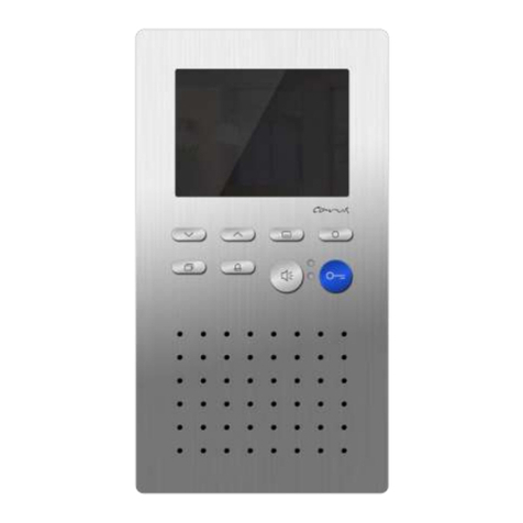
TCS IVW2221-015x User manual

Product information
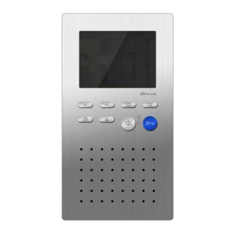
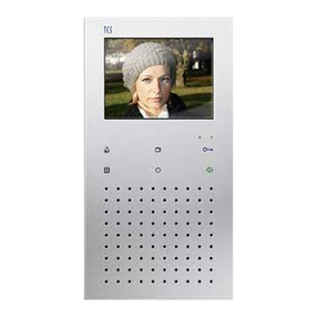
Video indoor station sky™
IVW2221-015x

2
Table of contents
Scope of delivery....................................................................................3
Safety instructions .................................................................................4
General safety regulations.....................................................................4
Installation –protective measures .........................................................4
Terms.......................................................................................................4
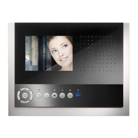
Device overview......................................................................................5
Indication and operating elements .......................................................6
Intended use............................................................................................8
Short description....................................................................................9
Mounting and installation ....................................................................10
Installation height.................................................................................10
Notes....................................................................................................10
Installation and connecting the lines .................................................10
Connection diagram.............................................................................12
Wiring diagram.....................................................................................13
5-wire special operation.......................................................................13
Commissioning.....................................................................................14
Error detection and indication ..............................................................14
Settings..................................................................................................14
Preset times.........................................................................................14
Configuration options...........................................................................15
Programming the function key with the Service Device.......................16
General information to the OSD menu.................................................16
Symbols and their meaning...............................................................17
Help function.....................................................................................19
Internal calls and control functions.......................................................19
Simple...............................................................................................19
ON/OFF.............................................................................................19
enocean ............................................................................................20
Sending a control function.................................................................20
Send internal call...............................................................................21
External image buffer...........................................................................21
Activate / deactivate the automatic image storage............................22
Store images manually......................................................................22
View stored images...........................................................................22
Delete a stored image.......................................................................23
Delete all stored images....................................................................23
Call up menu ring tone parameter.....................................................23
Set ring tone volume .........................................................................24
Ring tone selection............................................................................24
3
Set conversation volume......................................................................24
Setting date and time of the image buffer............................................25
Set image parameter ...........................................................................26
Symbols in the live image .................................................................26
Set contrast, brightness and color saturation....................................26
Reload factory setting..........................................................................27
Selecting a camera by stepping with the image button........................27
Short messages...................................................................................27
Read short messages .......................................................................27
Delete short messages .....................................................................28
Technical data.......................................................................................28
General to the conduit in TCS video systems ...................................29
6-wire operation...................................................................................29
Principle loop resistance...................................................................30
Measurement loop resistance...........................................................30
Max. number of IVW2221 in 6-wire operation......................................31
FAQ........................................................................................................31
Cleaning.................................................................................................34
Conformity.............................................................................................34
Information on disposal.......................................................................34
Warranty................................................................................................35
Spare parts............................................................................................35
Service...................................................................................................35
Scope of delivery
1 x IVW2221-015x
1 x adaptor plate of the IVW2221-015x
1 x product information
Accessories sheet for installation (1 x release bracket, 2 x fastening
screws, 2 x dowels, 1 x jumper terminating resistor )
Accessories sheet for user (1 x instruction manual, 1 x release bracket)

4
Safety instructions
General safety regulations
!
Attention! Mounting, installation, commissioning and repair of electri-
cal devices has to be carried out only by qualified electricians. The
current standards for the installation of door communication systems
must be observed!
When working in systems with 230 V mains voltage, the safety require-
ments according to DIN VDE 0100 must be observed.
When installing TCS:BUS systems, the general safety regulations for
telecommunication systems according to VDE 0800 must be observed:
separated cabling of heavy and low current lines,
minimum distance of 10 cm for common cabling,
use of separators between heavy and low current lines in shared cable
ducts,
use of standard telecommunication lines, e.g. J-Y (St) Y with 0.8 mm di-
ameter,
existing lines (modernisation) with deviating cross sections can be used in
compliance with the loop resistance.
Installation –protective measures
!
With suitable requirements to protect against lightning, it has to be
ensured that a voltage of each 32 V DC is not exceeded.
Terms
Main door call
Door call from the door with the main serial number (according to
serial number sticker at the device and the package). Main door
calls for front-door stations with ≤door call AS-border and > door
call AS-border can be realised.

5
Sub door call
Call from a front-door station, with different buttons different ring
tones can be generated at an indoor station.
Thus the ring tone distinguished by the used serial number. The
indoor station occupies an area of five serial numbers: Serial
number SN (according to serial number sticker), SN+1, SN+2,
SN+3, SN+4. Each of these serial numbers generate a different
ring tone.
Programming the bell buttons of the front-door station with a sub
door call can be realised via Service Device and configoTM.
On-Screen-
Display (OSD)
Menu, which is shown on the screen and activated with the menu
button of the device.
Device overview
Image button
Loudspeaker
Microphone
Navigation button UP
Navigation
button DOWN
Call OFF button
Screen
Menu button
Indication LED, green
Indication LED, red
Door release button
Speech button
Funkcion key

6
Indication and operating elements
Name
Function
Screen
display of the video image
indication of ring tone parameters and image
parameters via OSD
Indication LED,
red
is ON: call OFF is activated
flashes OFF: door release automatic or call
diversion is activated
Indication LED,
green
is ON: incoming door call or internal call,
speaking is activated
blinks
3 x: indication voice channel/video channel is
busy
permanent: new images are recorded or un-
read short messages
Door release
button
open the door (= preset ex works)
end speaking
trigger light switch function*
Speech button
call acceptance, speaking activated,
simplex communication
end speaking
Call OFF
button
ring tone stopper
end speaking, if IVW2221 is configured as
simplex communication device (with device
configurator configoTM)
Image button
activation of the video image
switch-over between different cameras
Function key
switch lights (= preset ex works)
control function 8 (OSD control function menu,
if necessary)
internal calling (OSD internal call menu, if nec-
essary)
door release automatic
call diversion

7
Menu button
Shortly press **
call main menu (in stand-by mode)
select parameters for modification (when image
parameter menu, ring tone parameter menu,
time setting are activated)
confirm the selection (if main, internal call or
control function menu and short message indi-
cation are activated)
call menu image parameters (when the video
image is activated)
select parameters for modification
directly to the indication image buffer or short
messages, if new recorded images or short
messages are not seen and the green LED is
blinking
Press long (longer than 4 s)
activate / deactivate central image buffer
Navigation
button UP
Shortly press
increase the value of the selected parameters
(if the image parameter menu or the ring tone
parameter menu is activated)
one entry in the list up (if the internal call or
control function menu is activated)
one menu point to the left (if the main menu is
activated)
show next image (if image buffer mode, repro-
duction are activated)
store image manually (if the video image is
activated)
increase conversation volume (if speaking is
activated, but the video image is deactivated)
Press very long (longer than 8 s) + naviga-
tion button DOWN:
load initial setting

8
Navigation
button DOWN
Press shortly
reduce the value of the selected parameters (if
the image parameter menu or the ring tone pa-
rameter menu is activated)
one entry in the list down (if the internal call or
control function menu is activated)
one menu point to the right (if the main menu
is activated)
store image manually (if the image is activat-
ed)
reduce conversation volume (if speaking ia
activated, but the image is deactivated)
Press long (longer than 4 s)
delete image (if the image buffer mode, repro-
duction are activated)
Press very long (longer than 8 s) + naviga-
tion button UP:
load initial setting
* if the light switch function is activated in the front-door station
** Button is working different, if a permanent image activation is configured on customer require-
ment. This performance feature can be activated resp. deactivated in the EEPROM.
Short keystroke: call up the main menu
Long keystroke (> 4 s): activation / deactivation of the image buffer
Long keystroke (> 8 s): call up the image setup menu
Intended use
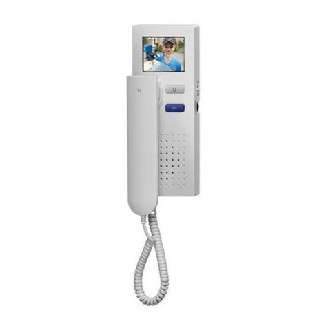
IVW2221 are video indoor stations with color display for hands-free talking
and simplex communication. They are suitable for the use in building
communication systems as well as in combined audio / video systems.
The operation is realised via buttons and the On-Screen-Display.
The video indoor station IVW2221 is suitable for surface-mount indoors.
!
The video indoor station IVW2221 always has to be installed on a
wall outlet one gang box or a flush-mount box, because the device
does not provide space for cabling.

9
Short description
hands-free talking / manually controlled simplex communication can be
activated
blue door release button
button for call acceptance resp. reversing key speak / listen, when simplex
communication is activated
1 function key, ex works: allocated with control function / alternative alloca-
tion can be activated: internal call, door release automatic, call diversion,
light, call up control function menu or internal call menu / can be adjusted
with configo™
image button to activate the video image resp. to switch-over between
different cameras
menu button for activation, control of the OSD menu
2 cursor buttons to navigate and adjust the OSD
13 polyphonic ring tones can be selected, can be adjusted via OSD
acoustic and optical call distinction between front-door, flat door and inter-
nal call
acoustic door call distinction, per bell button 4 different ring tones
acoustic door call distinction for 2 doors
ring tone mute with optical indication
OSD based: max. 10 internal calls and max. 10 control functions with
name can be triggered / adjustable with configo™
OSD based: operation of the central image buffer (FVM1000-0400)
ring tone volume can be adjusted in 8 steps via OSD
conversation volume can be adjusted in 8 steps via OSD
brightness, contrast, color saturation can be adjusted via OSD
1 parallel call can be activated with configo™
max. 10 short messages can be received and indicated
optical indication for new stored images in the central image buffer
(FVM1000)
optical short-term memory of door calls
optical indication of a busy line when a voice connection is established
optical indication for unread short messages
the device is equipped with a connection for floor push button
audio privacy function and automatic call cut OFF

10
Mounting and installation
Installation height
For an optimal viewing angle, we recommend an installation height of
1.60 m (top edge of the device).
Notes
!
Attention!
The video indoor stations have to be installed and removed only
voltage-free!
!
When mounting the mounting plate on uneven ground, please do
not over-tighten the screws as it can cause a deformation of the
mounting plate. Thus, you may not be able to snap on the device or
the secure contacting may be affected.
Installation and connecting the lines
Installation
The indoor station always has to be installed on a flush-mount socket
or a wall outlet one gang box.
Position the adaptor plate on the socket / box.

11
Connecting
Connect the lines to the plugable
terminal according to the labbelling.
(Therefore, the terminal can be remo-
ved.)
Put the terminal on the contacts.
Setup the indoor station as end device
Put the terminating resistor J1 on the
two left contacts, if the device is in-
stalled at the end of a TCS:BUS vid-
eo strand.
(ex works) not plugged
plugged
a
b
E
P
M
C
V1
V2
Install the adaptor plate
Do use the adaptor plate only as tool
to mark the holes.
Do not use the adaptor plate as drill-
ing template!
Install the adaptor plate directly on
the flush-mounted socket or on the
wall (left and right) with the 2 included
screws.
The protective foil serves to conserve
the contact reliability and prevents
e.g. an overpainting. The foil can be
removed during the installation of the
adaptor plate. Remove the foil only
before installing the device!
Adaptor plate
Protective foil

12
Install the device
Remove the protective foil.
Take the device into both hands.
Put it on at the adaptor plate.
Press the device flat onto the adaptor
plate (1) and push the device careful-
ly vertical downwards (2), until the
holes in the back of the device slide
over the lock bolts.
Push down the device until the stop.
4 lock bolt
Deinstall the devide
For deinstalling the device you need
the included unlocking bracket.
Insert the unlocking bracket into the
opening in the adaptor plate behind
the device (1).
Push up the device (2) and draw it off
forwards you (3).
Connection diagram
1
3
2
1
2
lock bolt

13
Wiring diagram
5-wire special operation
If only 5 wires are available to connect
the device, that the M-wire cannot be
connected, it is possible to use the 5-
wire special operation.
!
The installation of a wire bridge between the wires b and M is only
permitted when special conditions are observed. For an optimal solu-
tion for your project please contact our Hotline.
Clip on the termi-
nating resistor, if
the device is
installed at the
end of a
TCS:BUS video
strand.
floor push
button
floor push
button

14
Commissioning
!
First install the system completely, than connect
it to voltage!
V1 and V2 must not be connected to the P-, a- or b-wire.
When connecting the video wires V1 (+) and V2 (-) the polarity is to be
observed.
Check the a-, b- and P-wire against each other for short-circuits.
Switch on the power supply.
Error detection and indication
Errors are signaled optically and acoustically:
single error tone when pressing any bell button and
permanent flashing of both LEDs.
The optical error indication stays active until the error is corrected.
Error causes
indication
error modes
error tone
clearance
a- and P-wire inter-
changed or short-
circuited
both LEDs
flash
exchange a- and P-wire or re-
move short-circuit,
device is in stand-by mode again
a- or M-wire: not
connected or not
supplied
connect a- resp. M-wire or check
power supply, device is in stand-
by mode again
button stucks
(pressed longer than
15 s)
free button at the IVW2210 or at
the floor push button, device is in
stand-by mode again
Settings
Preset times
length of call
2 min
remaining conversation time after
pressing the door opener
4 s
image switch time
80 s

15
blinking period of the green LED, if
“video/speech channel is busy“ when
pressing the speech button or press-
ing the image button
3 s
3 x blinking
internal stand-by time
ca. 30 s
floor door release time
ca. 30 s
timeout menu ring tone parameter
10 s
timeout menu image parameter
10 s
Configuration options
Function
manual
TCSK-01
configoTM
as of version
1.6.x
fixed simplex communication
–
–
x
simplex communication to the front-
door station
–
–
x
ring tone volume
menu
–
x
ring tones for door calls, sub door
calls, internal calls and floor calls
menu
–
x
call diversion
–
x
x
door release automatic
–
x
x
10 internal calls via OSD
–
–
x
10 control functions via OSD
–
–
x
internal call via function key
–
x
x
control function 8 via function key
–
x
x
reset switching lights
–
x
x
parallel allocation
–
x
x
floor door release function on / off
–
–
x
automatic hands-free talking after
internal call on / off
–
–
x
define video AS threshold and door
call AS threshold
–
–
x
image activation by floor call
–
–
x
allocate short message groups
–
–
x
image buffer FVM1000 always
blocked
–
–
x
image buffer (in comfort mode)
FVM1000 on / off
–
–
x

16
* cannot be shown as text in the display
Programming the function key with the Service Device
The indoor station is acting as a simplex communication device. The
commands “9“ have to be used for configuring comfort simplex communi-
cation devices (see product information Service Device). A programming
with the commands “9“ has to be initiated with the command *95#Ser.-
No.# one-time only. Then the programming of the function key is to be
realised with the Service Device.
initiation
call diversion
door release automatic
internal call
control function 8
reset light switch function
parallel allocation
Note: Deactivation of the parallel alloca-
tion corresponds to the parallel alloca-
tion to serial number 0.
Ser.-No. = serial number of the indoor station which is to be configured new
DestSNo.= serial number of the destinated indoor station, to which the call is to be redirected
IntSNo. = serial number of the destinated indoor station, which is to be called intern
ParSNo. = serial number of the indoor station, to which the indoor station that is configured
new is to be allocated
General information to the OSD menu
The navigation in the OSD menu, in the image buffer indication and Live
image is realised with the navigation buttons UP and DOWN.
The OSD menu main menu can be switched on, if no Live image is shown
and if the indoor station is in stand-by mode, that means that no voice
connection is established and no door call has come in.
Symbols in the OSD menu are only shown if the respective function was
configured. In delivery state, not all possible functions are configured.

17
The live image is activated by pressing the image button or the speech
button or when a door call is received.
The OSD menu or the image buffer indication is switched off automatically
after 10 s, if no button is pressed. Or: Press the function key to leave the
menu.
The live image ends automatically after 80 s without any operation, by
ending the communication or when a video channel is used by another
device (not in case of a voice connection).
Main menu
Symbols and their meaning
sym-
bol
meaning
sym-
bol
meaning
ring tone selection for door calls
<= AS threshold
0...9
indication of adjusted values as
number
ring tone selection for door calls
> AS threshold
Label for call setting menu
ring tone selection for internal
calls
image buffer; automatic image
recording activated = green,
deactivated = red
ring tone selection for floor calls
menu send internal call
ring tone selection for sub ring
tone 1
menu send control function
symbol of the
selected menu
symbol
main menu
selected parameter
pictogram bar
for parameter selection

18
ring tone selection for sub ring
tone 2
menu for time setting of the
image buffer menu
ring tone selection for sub ring
tone 3
main menu
ring tone selection for sub ring
tone 4
menu short messages
ring tone volume
screen to read a short message
set contrast
delete short messages
set brightness
set date
set color saturation
set time
label camera for fading in the
AS address
delete image buffer (all stored
images)
call diversion activated
animated hourglass as progress
indicator
door release automatic acti-
vated
X
no stored images in the
FVM1000
ring tone mute activated
set converation volume

19
Help function
To simplify the operation of the device,
symbols are faded-in in the upper right
corner when calling the live image, the
main menu and the sub menus. The
symbols indicate, which button are
available in the respective screen. The
fade-in ends automatically after 5 s or
at the first keystroke.
symbol
meaning
navigation buttons UP, DOWN can be used to operate within the menu.
menu button can be used to confirm.
function key can be used as cancel button.
navigation button DOWN can be pressed and hold for 4 s.
Internal calls and control functions
The plain texts, which should appaer in the selection menu, can be set
exclusively with the configuration software configo™. Internal call desti-
nations or control processes can be entered there as plain text.
10 internal calls and 10 control functions can be send via the OSD menu.
Simple
By any triggering, the identical control protocol is send. There is no indi-
cation of the state of the device, which is to be switched. The serial num-
ber and the control function number can be configured as parameter.
Thus, it is possible to automatically generate the own serial number of
the video indoor station IVW2221.
ON/OFF
Alternating, two different control protocols with the same serial number
are sent. One control function number is intended for switching-on and
one for switching-off. Via two different symbols, which appear interde-

20
pendently in front of the list entry, the latest switched status can be seen.
Here, the two control function numbers as well as the serial number can
be configured, whereby the device-individual serial number can be creat-
ed, if required.
enocean
This function is realised identically to the IMM1100 to make sure that an
enocean radio interface FBI4200 can be connected. It can be also used
to indicate switching states without influencing these itself. When trigger-
ing the list entry, a control function with configurable serial number is
sent. The control function number can be selected freely (0 to 200 is pos-
sible). Independent from sending the protocols, the receiving of control
protocols with the configured serial number causes the switch-over of
states, which is indicated under b) by symbols in front of the list entry.
Thus, the control function numbers 01 and 03 realise the state OFF and
the numbers 02 and 04 the state ON.
Sending a control function
Triggering the control function can have three different effects:
A control protocol is sent (no indication in the menu).
Two different control protocols are send alternately (indication in the menu
with red/green point). The color of the point shows the triggered switching
process, but not the actual state of the device which is to be switched.
A control protocol is sent and the execution of the switching process is
indicated in the menu by a red/green point.
Press the menu button. Select the symbol
Send control function . Or call up the
menu with the function key, if the device is
configured accordingly.
Select the required function with the naviga-
tion buttons UP or DOWN.
Trigger by pressing the menu button. An
acknowledgement tone sounds. The OSD is
switched off after 5 s (or switches back to
the live image).
Table of contents
Other TCS Intercom System manuals

TCS
TCS ISH3022-0140 User manual

TCS
TCS ISW3330 User manual

TCS
TCS ISH3030-0140 User manual

TCS
TCS ISH3030 Instruction manual

TCS
TCS AVU14 0 Series User manual

TCS
TCS ISH3022-0140 User manual

TCS
TCS PSC2 0 Series User manual

TCS
TCS Carus Adapto User manual

TCS
TCS PVU14 0-0010 Series User manual

TCS
TCS Tasta Series Instruction manual

TCS
TCS ECOOS:FIVE User manual

TCS
TCS AMI Series User manual

TCS
TCS AVC11010-0010 User manual

TCS
TCS PVE14 0-0010 Series User manual

TCS
TCS ISW3030-0140 User manual

TCS
TCS SKYLINE:TEN BASIC User manual

TCS
TCS ISW3130-0140 User manual

TCS
TCS IMM2500 User manual

TCS
TCS AVU940x0 User manual

TCS
TCS IVH3222 User manual