CSI CSI-DSP85-PS7 User manual

CSI-DSP85-PS7/ CSI-DSP85N-PS7
&
CSI-DSP85-PSS8/CSI-DSP85N-PSS8
InstallationManual


Table of Contents
Document Purpose / Intended Users ................................................................................................................................. 4
Application ........................................................................................................................................................................... 4
Safety Guidelines................................................................................................................................................................. 4
Product Registration Information....................................................................................................................................... 4
Important Safety Information ............................................................................................................................................. 5
Product Introduction ........................................................................................................................................................... 5
Terms used in this manual ................................................................................................................................................. 5
700 MHz Filter Naming Convention and Band Plan............................................................................................................ 6
800 MHz Filter Naming Convention and Band Plan............................................................................................................ 7
Functional Overview ............................................................................................................................................................ 8
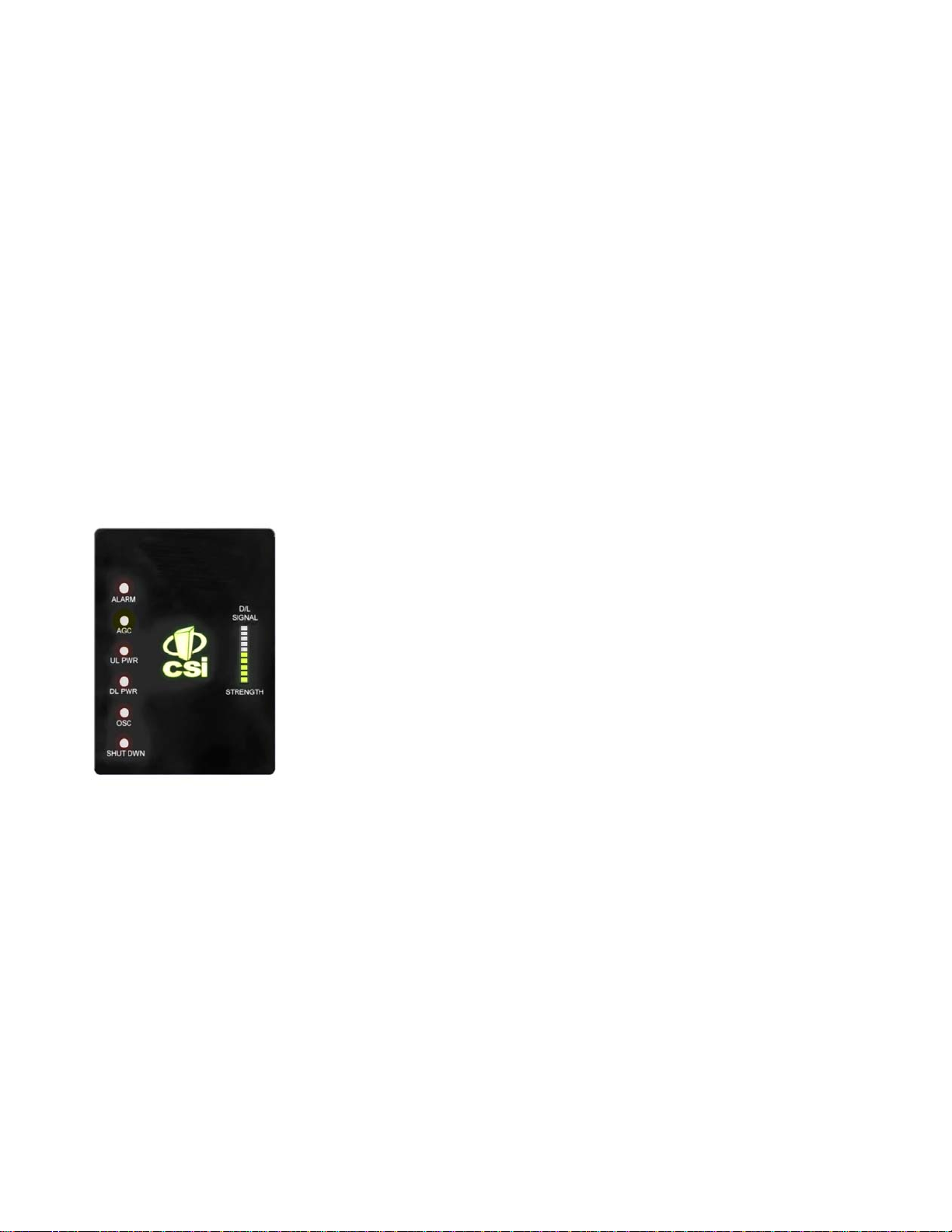
LED Indicators ..................................................................................................................................................................... 8
Local Communication Interface Ports ............................................................................................................................... 9
Approximate Signal Strengths of Bargraph Display ......................................................................................................... 9
Ethernet................................................................................................................................................................................ 9
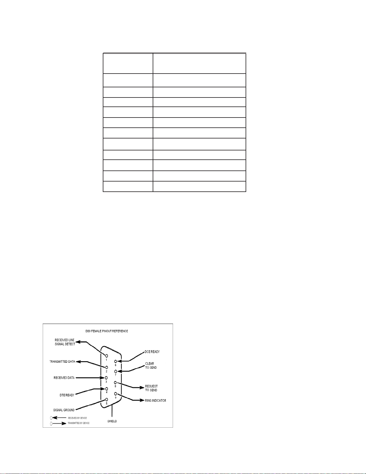
EIA232 Pin Specifications ................................................................................................................................................... 9
USB Interface....................................................................................................................................................................... 9
Monitoring & Alarms ......................................................................................................................................................... 10
System Set-Up Considerations ........................................................................................................................................ 10
Selection of external attenuators to be used in line with the Antenna Port(s) ............................................................. 10
DONORPORT ......................................................................................................................................................................11
SERVERPORT .....................................................................................................................................................................11
Attenuator Selection Guidelines........................................................................................................................................11
Wall Mounting the CSI-DSP85, Digital Repeater (Standard Model)................................................................................ 12
Wall Mounting the CSI-DSP85N, Digital Repeater (Weather Resistent Model) ............................................................. 13
Dry Contact Terminal......................................................................................................................................................... 14
Optional Accessories ....................................................................................................................................................... 14
Circuit Operational Description ........................................................................................................................................ 15
Important Installation Notes ............................................................................................................................................. 15
Functional Block Diagram ................................................................................................................................................. 15
Mechanical Specifications, Weather Resistent Model................................................................................................... 16
Mechanical Specifications, Standard Model ................................................................................................................... 16
AC Power Specifications .................................................................................................................................................. 16
Operating Power Parameters .......................................................................................................................................... 17
Environmental Requirements ........................................................................................................................................... 17
Mechanical Drawing, Standard Model ............................................................................................................................. 18
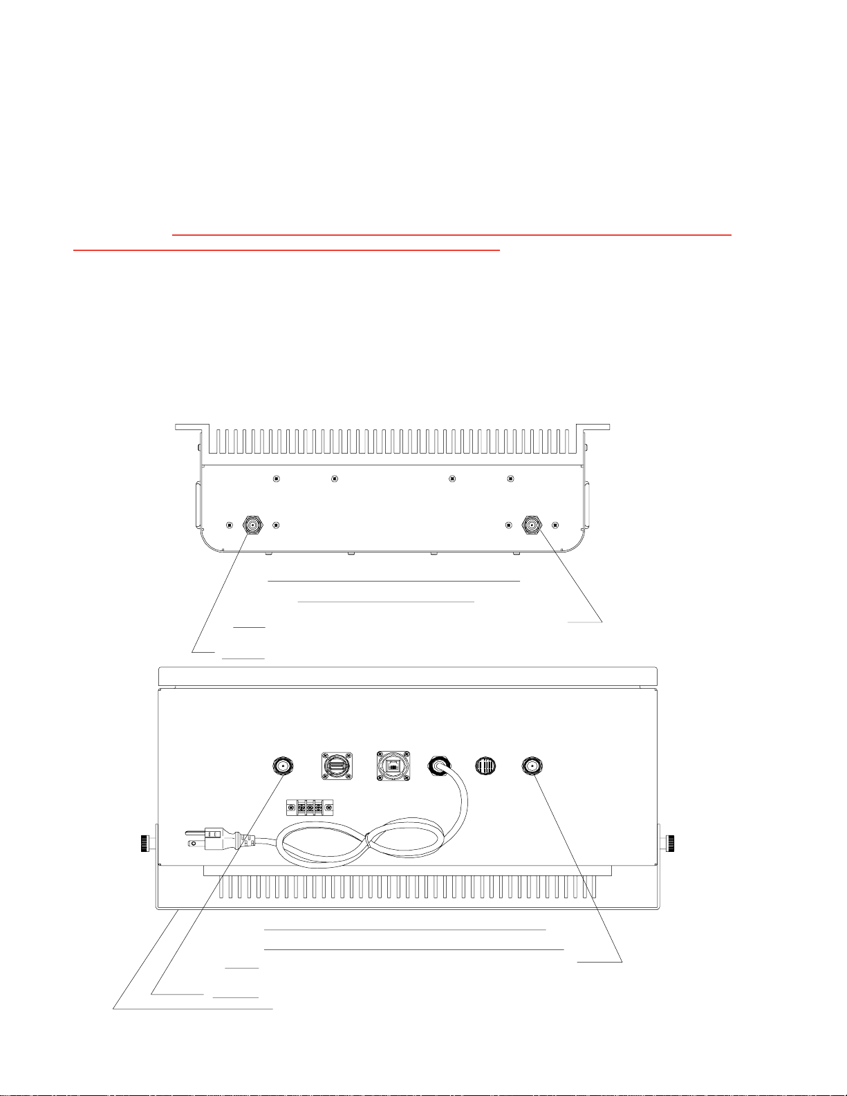
Mechanical Drawing, Weather Resistent Model ............................................................................................................. 19
System Status: .................................................................................................................................................................. 20
Web based GUI Session.................................................................................................................................................... 20
Local Network:................................................................................................................................................................... 21
Program a Filter: ................................................................................................................................................................ 22
RFConfiguration: ............................................................................................................................................................... 22
Remote Network:............................................................................................................................................................... 23
SNMPConfiguration: ......................................................................................................................................................... 23
Install &Upload: ................................................................................................................................................................. 24
System Health:................................................................................................................................................................... 24
Reboot: ............................................................................................................................................................................... 25
AlarmConfiguration: ......................................................................................................................................................... 25
E-mailConfiguration: ......................................................................................................................................................... 25
LogConfiguration: ............................................................................................................................................................. 26
Text Menu Interface (Local Access) ................................................................................................................................ 26
Terminal Emulation Program ............................................................................................................................................ 27
Terminal Emulation Set-up................................................................................................................................................ 28
TMILogin ............................................................................................................................................................................ 29
Telnet Session (Remote Access) ..................................................................................................................................... 31
Telnet Session Login ......................................................................................................................................................... 32
Modem Interface (Remote Access with login) ................................................................................................................ 33
AdditionalTips ................................................................................................................................................................... 34
Suggested spectrum analyzer setting:............................................................................................................................ 36
RFNotes: ............................................................................................................................................................................ 36
Industry Certifications/Registration Numbers:................................................................................................................ 37
Index................................................................................................................................................................................... 38

-4-
Product Registration Information
DISCLAIMER:All information and statements contained herein are accurate to the best of the knowledge
ofCellularSpecialties, Inc.(CSI), butCellularSpecialties makes no warrantywithrespectthereto, including
without limitation any results that may be obtained from the products described herein or the infringement
by such products of any proprietary rights of any persons. Use or application of such information or
statements is at the users sole risk, without any liability on the part of Cellular Specialties, Inc. Nothing
herein shall be construed as licence or recommendation for use, which infringes upon any proprietary
rights of any person. Product material and specifications are subject to change without notice. Cellular
Specialties’ standard terms of sale and the specific terms of any particular sale apply.
The general safety information in this guideline applies to both operating and service personnel.
Specific warnings and cautions will be found in other parts of this manual where they apply, but
may not appear in this summary. Failure to comply with these precautions or specific warnings
elsewhere in the manual violates safety standards of design, manufacture, and intended use of
equipment. Cellular Specialties, Inc. assumes no liability for the customer’s failure to comply with
these requirements:
Grounding
This Digital Repeater system is designed to operate from 100-240 VAC and should always
be operated with the ground wire properly connected. Do not remove or otherwise alter the
grounding lug on the power cord.
Explosive Atmospheres
To avoid explosion or fire, do not operate this product in the presence of flammable
gases or fumes.
Lightning Danger
Do not install or make adjustments to this unit during an electrical storm. Use of a suitable
lightning arrester, such as CSI’s model number CSI-CAP, is very strongly recommended.
No User Serviceable Parts Inside
HAZARDOUSVOLTAGESARE PRESENTWHENTHECOVERISREMOVED.Openingthe
chassis will void your warranty. If you suspect a malfunction with this product, call your dealer or
the Cellular Specialties Support Line at: (603) 626-6677, Toll Free (USA) 1-877-844-4274.
Safety Guidelines
This guide should be applied whenever a need exists to add Digital Repeater capability to an
existing system or when this capability is being included with a new installation.
Application
Document Purpose / Intended Users
The purpose of this document is to provide a step-by-step procedure to help the experienced
technician/engineer install and commission an in-building wireless enhancement repeater
system using CSI’s Digital Repeater. Following the procedures outlined will minimize risks
associated with modifying a live system and prevent service interruptions. This document
assumes the technician/engineer understands the basic principles and functionality involved
with Repeater and in-building systems. It is geared to the practical concerns of the installer.
The serial number may be found on the label on the bottom panel near the power
connectors. Note this number below. Retain this manual, along with proof of pur-
chase, to serve as a permanent record of your purchase.
MODELNUMBER SERIALNUMBER DATE OF PURCHASE
POINT OF SALE COMPANY

- 5 -
Cellular Specialties, Inc. (CSI) developed the DSP85 digital repeater for use within enclosed structures where signal from local dispatch
sites is insufficient to operate on scene communication equipment. Adequate signal must be available outside the structure as a prerequi-
site to achieving in-building coverage. The Digital Repeater is connected to an external antenna, usually on the roof, and to one or more
internal antennas placed strategically throughout the area where wireless service is desired.
The external antenna typically is directional, such as a “yagi”. Internal antennas are typically omnidirectional, although various other types
may be used depending on the coverage application. The CSI DSP Repeater amplifies both the “uplink” (Transceiver to tower) &
“downlink”(tower to Transceiver) signals thus facilitating communications to and from the intended wireless infrastructure.
With a maximum total of +85dB nominal gain on both the up and down links, gain can be adjusted over a range from +53.5dB to +85dB in
0.5dB steps. Control of the repeater is achieved utilizing a computer connected to comm. port 1 or 2 or via a Crossover Ethernet cable
connected to the Ethernet port. There are also LED indicators near the display to indicateALARM status,AGC status, UL PWR, DLPWR,
OSC,SHUTDWNandaD/LSIGNALSTRENGTHbargraph.
A specific filtering process modifies each amplification chain. This process digitally converts the assigned spectrum and then applies
digital signal processing (DSP) techniques. DSP is used to create passbands that selects the RF energy passing through either the uplink
or downlink paths. After the digital processing is complete, the information is converted back to an analog signal that is applied to the
remaining stages of amplification. The resulting signals emitted by the repeater are specific to the network service providers’ require-
ments. If these requirements change, only the DSP configuration parameters need change in order to adapt. Configuration parameters are
created at the factory and supplied as files that may be downloaded to the repeater. The filter set configurations stored in memory
determine the unit’s adaptability to various field applications. The following pages describe the public safety band plan as well as the
convention CSI uses to identify and store the files that make up the filter set. All DSP85 repeaters are shipped with an active filter set that
is programmed according to the ordering parties’ specifications. In most cases, the installer will not have to program a filter.
AGC= Automatic Gain Control ERP= Effective Radiated Power
APC= Automatic Power Control FPGA= Field Programmable Gate Array
AUI= Attachment Unit Interface LED= Light Emitting Diode
CPU= Central Processing Unit OIP3= Third-Order Intercept Point
CSI= Cellular Specialties, Inc. RF= Radio Frequency
DAS= Distributed Antenna System SBC= Single board Computer
DHCP= Dynamic Host Configuration SNMP= Simple Network Management Protocol
Protocol TMI= Text Menu Interface
DSP= Digital Signal Processing USB = Universal Serial Bus
EEPROM= Electrically Erasable UHCI = Universal Host Controller Interface
Programmable read-
only Memory
Antennas used for the purpose of radiating signals indoors are limited to a maximum gain of 3 dBi. The outdoor antenna used for the
purpose of communicating to the wireless infrastructure is limited to 14dBi gain, or any combination of gain and loss that equates to
14dB at input. Each antenna must be positioned to observe minimum separation requirements from all users and bystanders. The
following guidelines should be used when considering separation distances.
INDOOR antennas must be placed such that, under normal conditions, personnel cannot come within 20 cm (~8.0 in.) from any inside
antenna. Adhering to this minimum separation will ensure that the employee or bystander cannot exceed RF exposures beyond the
maximum permissible limit as defined by section 1.1310 i.e. limits for General Population/Uncontrolled Exposure.
OUTDOOR antenna must be positioned such that, under normal conditions, personnel cannot approach closer than 183 cm. (~6 ft.). A
directional antenna having a maximum gain of 14 dBi is used, precautions should be taken to prevent personnel from routinely passing
through the main radiation beam at a distance closer than specified.
Product Introduction
Terms used in this manual
Important Safety Information

- 6-
700 MHz Filter Naming Convention and Band Plan
CSI Public Safety 700 MHz Band Filter File Naming Convention
Single Channel Block Filter File Name Example
7n9-168-0 Public Safety 700 MHz band, 6.25 KHz
Cannels, Uplink Start Freq of 794.0500 MHz,
Uplink Stop Freq of 795.0500 MHz, Downlink
Start Freq of 764.0500 MHz, Downlink Stop
Freq of 765.0500 MHz with standard guard
band.
Band
ID Channel
Width ID
Start Channel
Number (see formula)
End Channel
Number (see formula)
DashIndicatesThat
All Channels between
Start and Stop Are
Included
Separator Variant
Designator
7w2-21_101-120-0
Multi Channel Block Filter File Name Example
Public Safety 700MHz band, 50
KHz Channels, 1st Channel Block
Uplink Start Freq of 797.0500
MHz, 1st Channel Block Uplink
Stop Freq of 798.0500 MHz, 1st
Channel Block Downlink Start
Freq of 767.0500 MHz, 1st
Channel Block Downlink Stop
Freq of 768.0500 MHz, 2nd
Channel Block Uplink Start Freq
of 802.0000MHz, 2nd Channel
Block Uplink Stop Freq of
803.0000 MHz, 2nd Channel Block
Downlink Start Freq of 772.0000
MHz, 2nd Channel Block Downlink
Stop Freq of 773.0000 MHz with
standard guard band.
Band
ID
Start Channel
1st Block (see formula)
End Channel
1st Block (see formula)
UnderscoreIndicates
the Gap Between
Channel Blocks
Start Channel
2nd Block (see formula)
End Channel
2nd Block (see formula)
Notes: 1. 7 = Public Safety Band 700 MHz
2. n = 6.25 KHz Channels, w= 50 KHz Channels
3. See the formulas to correlate frequencies to the
channel numbers used in this file name convention.
4. CSI DSPII repeaters are capable of up to four channel
blocks in one file configuration.
Channel
Width ID
To determine frequencyfrom channel number use one of the following formulas:
For NBDL Start: (Channel # x 0.00625) + 763.99375 = Frequency
For NBDL Stop: (Channel # x 0.00625) + 764.0000 = Frequency
For NBUL Start: (Channel # x 0.00625) + 793.99375 = Frequency
For NBUL Stop: (Channel # x 0.00625) + 794.0000 = Frequency
For WBDL Start: (Channel # x 0.05) + 766.95 = Frequency
For WBDL Stop: (Channel # x 0.05) + 767.0000 = Frequency
For WBUL Start: (Channel # x 0.05) + 796.95 = Frequency
For WBUL Stop: (Channel # x 0.05) + 797.0000 = Frequency
DSPII Public Safety 700MHz Band Plan
Mobile
(MHz)
Base
(MHz)
763
793 803
773
797
767
Mobile
(MHz)
Base
(MHz)
Narrow Band
6.25KHz Channels Wide Band
50KHz Channels
805
775
Narrow Band
6.25KHz Channels

CSI SMR 800 Filter File Naming Convention
Single Channel Block Filter File Name Example
sp9-81-0 SMR 800 band, P25 Modulation, Uplink
Start Freq of 806.1000 MHz, Uplink Stop
Freq of 807.0125 MHz, Downlink Start
Freq of 851.1000 MHz, Downlink Stop
Freq of 852.0125 MHz with standard
guard band.
Band
ID Modulation
ID
Start Channel
Number (see formula)
End Channel
Number (see formula)
Dash Indicates That
All Channels between
Start and Stop Are
Included
Separator Variant
Designator
sp9-81_1201-1281-0
Multi Channel Block Filter File Name Example
SMR 800 band, P25 Modulation, 1st
Channel Block Uplink Start Freq of
806.1000 MHz, 1st Channel Block
Uplink Stop Freq of 807.0125 MHz,
1st Channel Block Downlink Start
Freq of 851.1000 MHz, 1st Channel
Block Downlink Stop Freq of
852.0125 MHz, 2nd Channel Block
Uplink Start Freq of 821.1125 MHz,
2nd Channel Block Uplink Stop Freq
of 822.0125 MHz, 2nd Channel
Block Downlink Start Freq of
866.1000 MHz, 2nd Channel Block
Downlink Stop Freq of 867.0125
MHz with standard guard band.
Band
ID Modulation
ID
Start Channel
1st Block (see formula)
End Channel
1st Block (see formula)
Underscore Indicates
the Gap Between
Channel Blocks
Start Channel
2nd Block (see formula)
End Channel
2ndBlock (see formula)
Notes:1. s =SMR 800 Public Safety Band
2. p = P25 Modulation
3. See the formulas to correlate
frequencies to the channel
numbers used in this file name
convention.
4. CSI DSP II repeaters are capable of up
to four channel blocks in one file
configuration.
To determine frequency from channel number use one
of the following formulas:
For DL Start: (Channel # x 0.0125) + 850.9875 = Frequency
For DL Stop: (Channel # x 0.0125) + 851.0000 = Frequency
For UL Start: (Channel # x 0.0125) + 805.9875 = Frequency
For UL Stop: (Channel # x 0.0125) + 806.0000 = Frequency
DSP II Public Safety 800MHz Band Plan
Mobile
(MHz)
Base
(MHz)
851
806 815
860
809
854
Mobile
(MHz)
Base
(MHz)
824
869
NPSPAC
(Public Safety)
Public Safety
B/ILT
Non-Cellular SMR
816
861
Expansion
Band
Guard
Band
817
862
ESMR
800 MHz Filter Naming Convention and Band Plan
- 7 -

-8-
The CSI-DSP85 repeater incorporates the following features for convenient operation, access, protection, and control.
•Network Configuration and Control using either a webpage style GUI through
any standard browser or a menu driven user interface using the serial port.
(Note: GUI does not require Internet access.)
•User Gain Control (affects all passbands)
•Automatic Gain Control
•Automatic Power Control
•Oscillation Protection
•Over Drive Protection (P.A. limiting)
•Under/Over Voltage Protection
•Fault Protection
•Alarm Notification - Local/Remote
•Upgrade Support - Local/Remote
•External Interfaces - USB/Ethernet/Serial
•Re-loadable filters - Local/Remote
•Web-based monitoring and control - Local/Remote
•Persistent Status and Error information
Automatic safety precautions are built into the amplifier system. In the case of a catastrophic system event, a shutdown circuit is incorporated
that will disable all emissions should the uplink input or downlink input be overdriven or should an oscillation or output overpower event occur. The
amplifier will periodically attempt to recover from the detected condition automatically. Warning light indicators are as follows:
UL PWR: Indicated by a red LED. Uplink power has been affected by a system event and
will need to be addressed by either the system software or a technician to
be reset to original system settings, using the GUI or text menu interface.
See the event log to determine the nature of the fault.
DL PWR: Indicated by a red LED. Downlink power has been affected by a system event
or condition, such as insufficient antenna isolation, and will need to be
addressed by either the system software or a technician to be reset to original
system settings, using the GUI or menu driven user interface. See the event log
to determine the nature of the fault.
OSC: Indicated by a red LED. An oscillation event has occurred or is occurring. The
system has been affected by the event and the problem will need to be
addressed by the system software or a technician to be reset to original ystem
settings. This is an indication of a major fault.
SHUT DWN: Indicated by a red LED. The RF stages of the unit are disabled due to an
unresolved system event such as oscillation, effectively taking the unit off
the air. The problem will need to be addressed by a technician before the on
air operation can be restarted. The repeater is not equipped with an ON/OFF
power switch. Hard power down will require that the unit be unplugged.
D/L SIGNAL
STRENGTH: Indicated by a green LED bargraph. This indicates the relative signal strength
being received from the cell site. Note: the last bar of the bargraph will turn
red in the event of very strong adjacent channel interference.
Alarm: Indicated by a red LED. The unit has sensed an alarm condition. This LED may
light alone or in conjunction with one of the other indicator LEDs. In both cases the
cause(s) can be reviewed by going to the System Health menu.
AGC: When Illuminated, this yellow LED indicates that automatic gain control is active
and has reduced the gain of the unit in order to prevent very strong input
signals from overloading the amplifier. The amplifier will periodically evaluate
input signal and attempt to recover from this condition.
Functional Overview
LED Indicators

EIA232 Pin Specifications
The diagram to the left is for reference only, it’s intended to provide
a quick source for pinout information in the event it should be
necessary to adapt your serial cable because of an unusual
connector configuration. In the vast majority of cases this
information will not be needed.
To allow monitoring and control, the CSI-DSP85-PSS8 is equipped with four ports that provide external communication access (1
Ethernet CAT-5, 2 DB-9 serial, and 1 USB). The Ethernet, CAT-5 port is provided as a primary communications port to the PC. One
serial interface provides communications to local PC and the second to an external modem when provided. The USB interface
provides a means to download files from a memory device and may also be used by an external modem. The DB-9 pin assign-
ments conform to the standard Electronic Industries Association (EIA232) specification. A diagram of the pin descriptions is
provided on this page for reference.
Connecting a null modem cable to one of the COM ports and using a terminal emulation program with a PC will allow communication
to the control processor’s Text Menu Interface (TMI). See command line interface section for further detail.
Approximate Signal Strengths of Bargraph Display
ILLUMINATED
BARS SIGNAL AT INPUT
CONNECTOR
0*
1
2
3
10
< -81 dBm
-81dBmto -79dBm
-78dBmto -75dBm
AdjacentChannel
Interference
4
5
6
7
8
9
-74dBmto -71dBm
-70dBmto -67dBm
-66dBmto -63dBm
-62dBmto -59dBm
-58dBmto -55dBm
-54dBmto -51dBm
The minimum measurable input level is -81 dBm at 85 dB gain, -71 dBm at 75 dB gain, -61 dBm at 65 dB gain, and -51 dBm at 55 dB gain.
The Universal Serial Bus (USB) interface conforms to
Intel’s Universal Host Controller Interface (UHCI) version
1.1 dated March 21, 1996. This interface will support data
transfer rates up to 12 Mbps and can be used for soft-
ware updates and filter file uploads.
*Note: During Power up, the repeater will require a approximately three minutes for the internal computer to boot up. During this
time the LEDs on the front panel will light and go out several times. When boot is complete and no alarm conditions exist, none of the
LED indicators will be illuminated. The CSI logo is illuminated when ever the repeater is powered. One or more bars on the LED
bargraph may also be lit, depending on the strength of the signal being received from the donor site. Signals weaker than -81dBM will
not illuminate any bars.
Do not unplug the unit while it is in the boot up process!
Local Communication Interface Ports
USB Interface
The Ethernet AUI conforms to IEEE 802.3 and is capable of
supporting 10/100 Mbps communications speeds. This port is
used to provide access to the GUI.
Ethernet
- 9 -

- 10 -
All cables should be checked for shorts and opens. Also verify that there are no cables with loose or poor connec-
tions. RF leakage could cause oscillation to occur under some conditions.
The rooftop antenna (Donor Antenna), if directional, should be checked for proper alignment along the calculated
compass heading. Typically, the directional antenna would be aimed at the same site that your handset uses, but it may
not always be so. It is critical the installer contact the service provider for information on, and approval
of, the site he or she has selected before the system is turned on.
If cables and alignment are acceptable and a problem persists, it may be necessary to use a spectrum analyzer to
examine the signal environment in which the repeater is operating. The existence of strong adjacent channel signals
within the frequency band(s) can cause the AGC to reduce the amplifier’s gain or cause alarms. In some cases
additional filtering or attenuation might be required to reject these unwanted signals. In some instances, the donor
antenna can be reoriented horizontally, to place the interference source in an antenna pattern “null”. There also may be
some cases where the interference from outside signals is so great that they cannot be filtered or otherwise reduced
or eliminated without expensive and possibly prohibitive measures. In these cases it may not be practical to use the
CSI-DSP85-PSS8 for providing coverage to these sites.
TO INSIDE ANTENNA TO OUTSIDE ANTENNA
1:1 PORT CONFIGURATION
STANDARD MODEL
Input: One single band port, from the single band donor.
Output: One single band port to the DAS.
There are no physical connections provided to specifically communicate system or alarm status. This information is
embedded in the information accessible via the communication ports described earlier.
TO INSIDE ANTENNA TO OUTSIDE ANTENNAUSB ETHERNET POWER
CCNCNO
Input: One single band port, from the single band donor.
Output: One single band port to the DAS.
1:1 PORT CONFIGURATION
WEATHER RESISTANT MODEL
MOUNTING BRACKET
Monitoring & Alarms
System Set-Up Considerations
Selection of external attenuators to be used in line with the Antenna Port(s)

- 11 -
If a CSI-DSP85 is installed in an area with very strong desired and/or undesired signals, it is important to ensure that the overall signal levels are
optimized to be within the best operating range of the repeater. Additionally, de-sensing of a nearby base station site must be avoided. These goals
can be accomplished by properly attenuating the antenna port(s) in the path of the donor antenna(s). In effect, one can imagine that the particular
repeater deployment is electrically moved farther from the base station using attenuators that are equivalent to increasing the path loss from the
donor antenna to the base station. The following potential outcomes result from the use of attenuators on the donor port(s) of the CSI-DSP85: Uplink
output power, as reported by the CSI-DSP85, is reduced by the value of the attenuation, protecting nearby base stations. Downlink signal to noise
ratio is high at the point of the attenuator, resulting in slight but negligible reduction in downlink performance. Other performance is essentially
unchanged.
DONOR PORT
Server port attenuation may also be necessary, particularly where a powered DAS is present. The selection guidelines below apply to both server
and donor ports. In order to properly measure uplink signal strength, a signal generator should be used. If a signal generator is not available, placing
a test call while under the server antenna with the least path loss to the repeater should provide reasonable data.
The following potential outcomes result from the use of attenuators on the server port(s) of the CSI-DSP85: Downlink output power, as reported
by the CSI-DSP85, is reduced by the value of the attenuation. Uplink incoming power from the DAS is reduced, along with potentially strong and/
or harmful out-of-band signals (including noise) that are generated by the DAS.
SERVER PORT
Attenuator Selection Guidelines
Accurate attenuator values need to be chosen to ensure that the maximum total power (higher of Composite or In-Band Input) applied to the donor
and server port(s) does not exceed the following thresholds:
Input Signal Max Gain Input Signal Max Gain
<-45 dBm 85dB -32.2 dBm 69dB
-44.3 dBm 84 dB -31.4 dBm 68 dB
-43.6 dBm 83dB -30.6 dBm 67 dB
-42.9 dBm 82dB -29.8 dBm 66 dB
-42.2 dBm 81 dB -29 dBm 65 dB
-41.5 dBm 80dB -28.2 dBm 64 dB
-40.6 dBm 79dB -27.4 dBm 63 dB
-39.7 dBm 78dB -26.6 dBm 62 dB
-38.8 dBm 77dB -25.8 dBm 61 dB
-37.9 dBm 76 dB -25 dBm 60dB
-37 dBm 75dB -24.4 dBm 59 dB*
-36.2 dBm 74dB -23.8 dBm 58 dB*
-35.4 dBm 73dB -23.2 dBm 57 dB*
-34.6 dBm 72 dB -22.6 dBm 56 dB*
-33.8 dBm 71dB -22 dBm < 55 dB*
-33 dBm 70dB
*We recommend padding this level due to potential for fluctuating signal.
-25 dBm is the maximum input signal level that should be applied to the repeater, even if the gain is lower than 55 dB.
Input signals exceeding these thresholds will result in composite input attenuation, called “ADC Protect” (Analog to Digital Converter Protection).
Output power is reduced whenever the above thresholds are exceeded by reducing the gain by 1dB for each 1 dB that the threshold is exceeded.
ADC Protect should not be confused with AGC (Automatic Gain Control), which reduces gain to prevent In-Band (measured) output power from
exceeding the specified maximum output level. To determine the total power applied to the donor and server ports, please reference the “Composite
Input” values as reported in the Web (“System Status”) or Menu (“Link Status”) interfaces (depicted and explained later in this manual).
Large delta’s between in-band and composite input signals:
Care should be taken to isolate the best donor site to ensure the least possible delta between in-band and composite downlink signals. If the
(downlink) composite input exceeds the in-band input by more than 3 dB for the SMR band the maximum output power will be reduced. Example:
Band (SMR)
In-Band Input -45 dBm
Composite Input -33 dBm
Max Gain = 70 dB
Max Output = 25 dBm

-12-
ITEM # QTY PART # DESCRIPTION
1 1EA CS10-38X-4XX** DSP85 REPEATER
2 1EA 453-1010-002 5V/24V POWER SUPPLY
3 1EA 780-0510-001 LINE CORD (AC POWER)
4 1EA 750-2171-001 MOUNTING PLATE (OPTIONAL)
5 1EA 750-2172-002 P/S MOUNTING BRACKET
**"X" WILL VARY WITH MODEL
AND BAND ORDERED
The following diagram illustrates the best method for mounting the repeater to a wall in an typical installation.
Note: for optimal cooling the unit should be mounted vertically on a wall with the antenna ports up.
Wall Mounting the CSI-DSP85, Digital Repeater (Standard Model)

-13-
The following diagram illustrates the best method for mounting the repeater to a wall in an typical installation.
Note: for optimal cooling the unit should be mounted vertically on a wall with the antenna ports down.
ITEM # QTY PART # DESCRIPTION
1 1EA CS10-XXX-4XX** DSP85N REPEATER
2 1EA 750-2268-001 MOUNTING PLATE
**"X" WILL VARY WITH MODEL
AND BAND ORDERED
Wall Mounting the CSI-DSP85N, Digital Repeater (Weather Resistant Model)

-14-
Warning: On the standard model, power supply cable connectors are keyed for proper orientation, but if forced can be
inserted incorrectly. Great care should be taken to avoid this as it may damage the connectors and/or the repeater. This does
not apply to the weather resistent model, which uses an internal power supply
Keyed for proper alignment, do not force
connector into place.
A complete line of accessories is available from Cellular Specialties, Inc. Check with your CSI distributor for any additional items
needed. Below are just a few examples suitable for most in-building needs.
•Directional Couplers
6dB - model number: CSI-DC6/700-2K/N
10dB - model number: CSI-DC10/700-2K/N
15dB - model number: CSI-DC15/700-2K/N
20dB - model number: CSI-DC20/700-2K/N
30dB - model number: CSI-DC30/700-2K/N
•Outside Donor Antenna
Yagi - model number: CSI-AY/806-960/14
Panel - model number: CSI-AP/698/2.2K/7-10
•UPS
Battery backup, 2 hr Single band
1 hour dual band - model number: CS48-985-600
Battery backup, 4 hr Single band
2 hour dual band - model number: CS48-985-601
•Power Dividers
2:1 - model number: CSI-SPD2/700-2.5K/N
3:1 - model number: CSI-SPD3/700-2.5K/N
4:1 - model number: CSI-SPD4/700-2.5K/N
•Grounding Kit - model number: CSI-GKIT
•Lightning Arrestor - model number: CSI-CAP
•Inside Omnidirectional Antenna
Quad-band - model number: CSI-AO/700/2.5K/3
•Mounting Kit
19” rack or wall mountable -
model number: CSI-RWM-DSP85
OptionalAccessories
This CSI Digital Repeater is equipped with an automatic amplifier safety shutdown circuit that will disable the transmitter, to prevent excessive
intermodulationandoscillation,shouldtheuplinkordownlinkoverloadsbe reached. The amplifier will periodically attempt torecover from thiscondition.
Inorder toprovide an indication of thisshutdown,a terminal blockmounted externallyis provided forremote monitoring. Terminals 1and 2, labeled NO
and NC respectfully, will toggle from open to close with major faults.
Dry Contact Terminal

-15-
Functional Block Diagram
•Inadequate isolation between the outside and inside antennas may cause regenerative feedback in the system. This
feedback can cause the amplifier to emit a continuous signal at maximum amplitude and, in some cases, interfere with normal
operation of the dispatch site. Careful consideration of the layout and placement of the system is imperative.
•The installer should refer to the Safety Guidelines section on page 4 and the Important Safety Information section on page 5 for
proper antenna selection and installation. To avoid serious injury or death and damage to the repeater, do not install donor or server
antennas near overhead power lines or high power components. Allow enough distance so that if antennas should fall they will
not come in contact with those components.
••
••
•Close proximity to the donor or server antennas with the repeater in operation may expose the user or installer to RF fields
that exceed FCC limits for human exposure.
WARNING!AMPLIFIERORHANDSETDAMAGEMAYOCCURIFAHANDSETISCONNECTEDDIRECTLYTOTHEREPEATERORTHE
COAXTHATLEADSTOTHEREPEATER.
Important Installation Notes
The repeater uses a single down-conversion/up-conversion scheme. There are multiple RF amplifier stages prior to each down-
converting mixer. The down-converting mixers are followed by a single IF amplifier. A Digital Signal Processor block then processes
the resultant digitized IF signal that was previously generated by an Analog-to-Digital Converter. The processed (filtered) digital signal
is fed to a Digital-to-Analog converter and then up-converted to RF. A driver amplifier and a final power amplifier make up the final gain
stages before application to the diplexer. The maximum total system gain (diplexer input to diplexer output) is nominally 85 dB for either
the downlink or the uplink paths with both links having independent manual and automatic gain controls (AGC).
AGC reacts to analog power detection on both the input and output of the uplink and downlink RF chains. A control algorithm
continuously monitors these detected values and dynamically adjusts various gain stages such that the net system gain
value, entered manually, is maintained without either exceeding FCC parameters or overdriving the A/D converters.
LEDs on the front panel display provide immediate visual indications of the unit’s primary power and major or minor alarm
status. The repeater features automatic shutdown protection, as a safety measure, should excessive drive be applied to the
input or an oscillation condition occur. When in a protected mode, a control algorithm determines the appropriate method of
recovery to a normal, previously defined state, or maintains the protection until manually reset. If recovery has been estab-
lished, the associated LED(s) will either be extinguished or available to be reset. The events
that trigger the error will be saved in the event log.
Circuit Operational Description

-16-
Color Satin Black
AC Voltage 100 - 240 VAC External Power Supply
AC Power Frequency 47 - 63 Hz
Box Weight 27.5 / 12.47 lbs/kg
Box Thermal Management Convection cooled Large heatsink
Surface Coating Powder Coat
AC Current 1.7 Amps @ 120 VAC
0.9 Amps @ 230 VAC
Repeater Size
Height 4.69 in.
Width 18.62 in.
Depth 11.25 in.
Heat Output 500BTU/Hr
Color Satin Black
Box Weight 35.5 / 16.103 lbs/kg
Box Thermal Management Convection cooled Large heatsink
Surface Coating Powder Coat
Repeater Size
Height 8.62 in.
Width 21.063 in.
Depth 16.906 in.
Parameter Specification Notes
Mechanical Specifications, Standard Model
Parameter Specification Notes
AC Power Specifications
Mechanical Specifications, Weather Resistant Model
Parameter Specification Notes

-17-
OIP3 Measured with 2 CW tones at 14
dBm/tone
Linear Output Power + 27dBm max Uplink and Downlink
SMR +26dBm** **AGC Set Point
Noise Figure (Avg) 5.0 dB AtMaximum Gain
Maximum RF input Power +10 dBm
without damage
Linear Gain 85 dB Factory Calibrated Gain
Pass Band Ripple +/-1.5 dB
Automatic Gain Control (AGC) 30 dB max In 0.5 dB steps
range
Manual Gain Control 53.5-85 dB max In 0.5 dB steps
RMS Vector Error (EVM) 3% max TDMA, EDGE, W-CDMA, CDMA2000, P25
CDMA RHO 0.98 min CDMA2000, 1x-EVD0
Spurious Emissions &
Applicable Documents
FCC -13 dBm max Per FCC part 2 and 90
Industry Canada -13 dBm max
Propagation Delay <2.5 usec
Input VSWR (Typ) <1.5:1
+ 43 dBm
Environmental Requirements
Relative Humidity 5% to 95% Non-condensing
Industrial Dust <15mg/m3 TelcordiaGR-63-CORE
Temperature Range 0 to +50 C
(-32 to +122 F)
00
00
1dB Compression Uplink and Downlink
+ 33 dBm
Connectors N-Female (2)
Operating Power Parameters
Parameter Specification Notes

-18-
CCNCNO
ETHERNETUSB
COM 1COM 2
POWER
DLPWR
ALARM
ULPWR
TO OUT SIDE ANTENNATO INSIDE ANTENNA
Mechanical Drawing, Standard Model

-19-
Mechanical Drawing, Weather Resistent Model
TO INSIDE ANTENNA TO OUTSIDE ANTENNAUSB ETHERNET POWER
CCNCNO

-20-
When login is complete the user is brought to the system status page. The links shown in the
navagation box on the left are activated by clicking on them.
Primary access to the repeater is gained using a LAN connection and a web browser
program such as Firefox by Mozilla, or Internet Explorer from Microsoft. The repeater ships
with the default IP address of 192.168.1.100, but it can be changed later if required.
If connecting directly to the repeater from a laptop or PC with a crossover CAT-5E cable or
over a LAN the user types the IP address of the repeater into the browser address line to
connect. (Note: Most users will need to update the TCP/IP settings on their computer to enable
connection to a host that has a static IP. Select “Use the following IP Address” and enter the IP
Address as follows: 192.168.1.x, where “x” = any number from 2 to 254 inclusive other than
100. The subnet mask is 255.255.255.0. Questions pertaining to these settings should be
referred to the user’s IT department or you may refer to the Additional Tips section at the end
of this manual.) When connection is made the user will be prompted for a user name and
password. For the purpose of the GUI session, the default user name is webuser and the
password is csi1234. This can also be changed as required. Internet access is not required
to use the GUI. (Note: If you are connecting using a laptop, verify that your Ethernet port is
powered. Some laptops will not allow Ethernet connection when on battery power. If this is
the case with the laptop you are using you will need to plug it in or update the power settings.)
System Status:
Web based GUI Session
This manual suits for next models
3
Table of contents
Other CSI Repeater manuals
Popular Repeater manuals by other brands

Nikrans
Nikrans NS-2000-Smart quick start guide

Vertex Standard
Vertex Standard VXR-9000V-H operating manual

Spectrum
Spectrum SCR1000 Operation and maintenance manual

Davis Instruments
Davis Instruments Long-Range Repeater installation guide

SEOHWA
SEOHWA SHPR19-F1 user manual

Redutelco
Redutelco PODRP20 user manual