CSI Alfa Laval SolidC-1 User manual

3008-0028
100002858-EN7 2016-10
Original manual
Instruction Manual
SolidC Pump


Table of contents
The information herein is correct at the time of issue but may be subject to change without prior notice
1. EC Declaration of Conformity ....................................................................... 4
2. Safety .................................................................................................... 5
2.1. Important information ............................................................................. 5
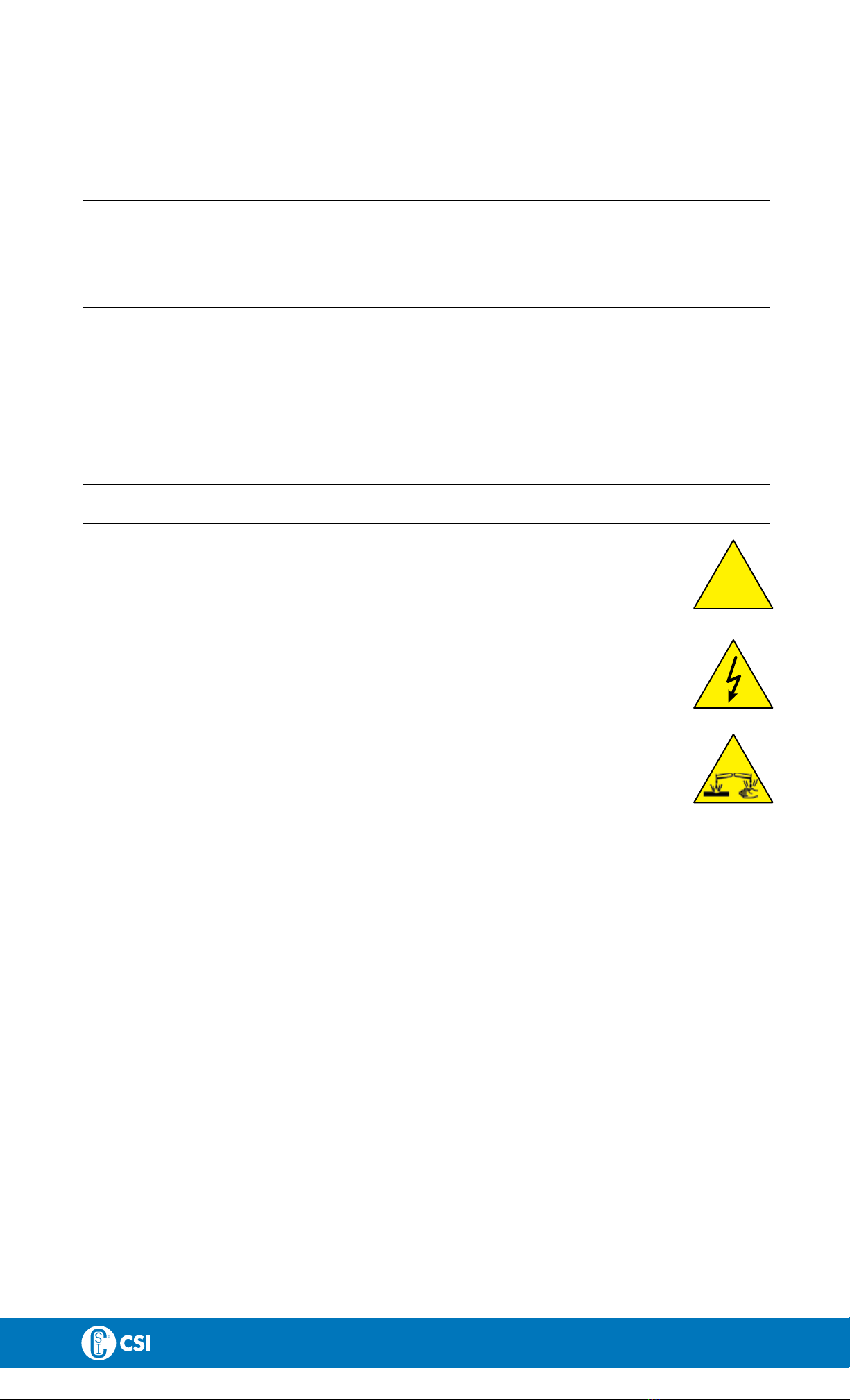
2.2. Warning signs ..................................................................................... 5
2.3. Safety precautions ................................................................................ 6
3. Installation .............................................................................................. 8
3.1. Unpacking/delivery ............................................................................... 8
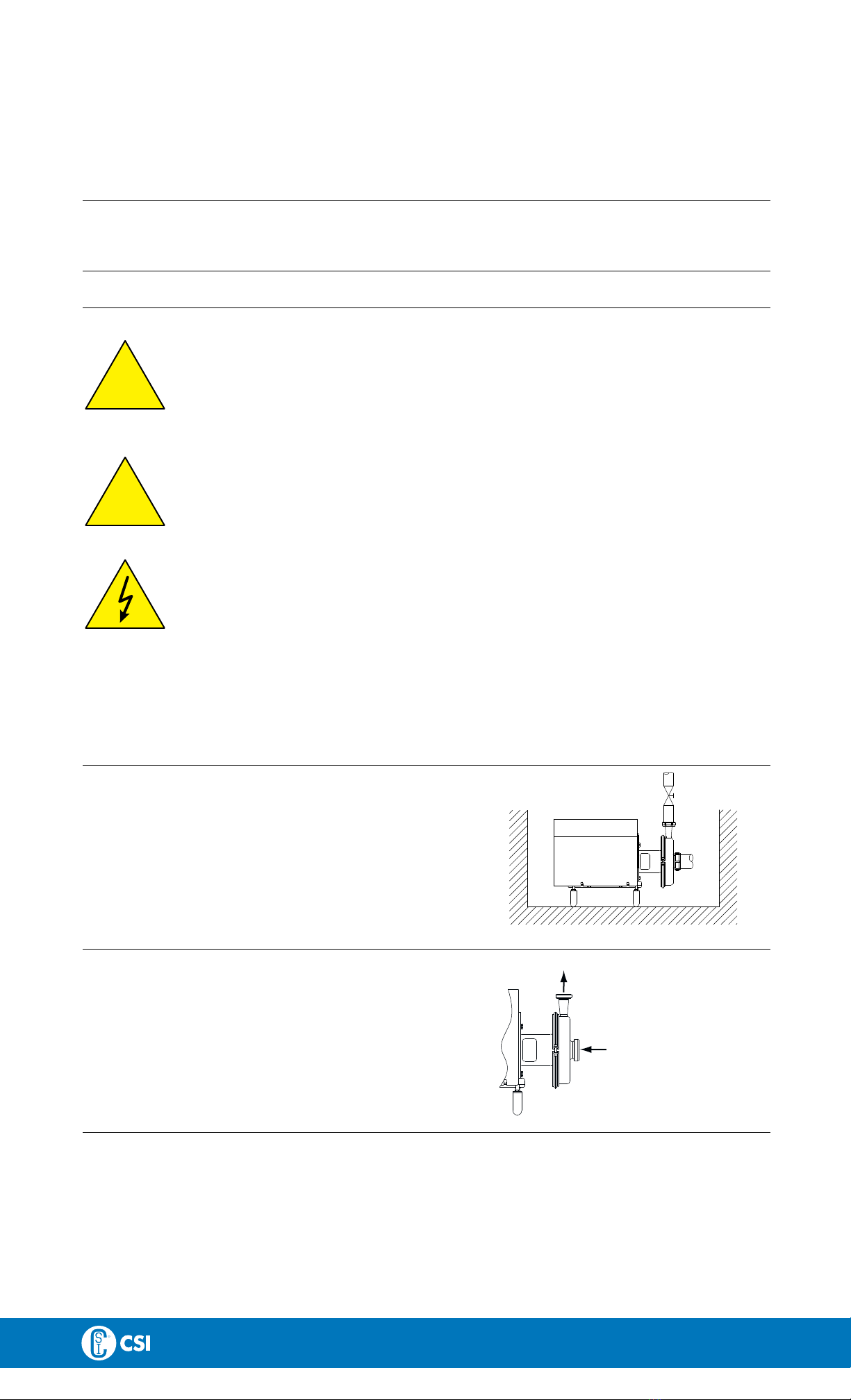
3.2. Installation ......................................................................................... 9
3.3. Pre-use check ..................................................................................... 10
3.4. Recycling information ............................................................................. 10
4. Operation ............................................................................................... 11
4.1. Operation/Control ................................................................................. 11
4.2. Trouble shooting .................................................................................. 13
4.3. Recommended cleaning ......................................................................... 14
5. Maintenance ........................................................................................... 15
5.1. General maintenance ............................................................................. 15
5.2. Cleaning Procedure ............................................................................... 16
5.3. Dismantling of pump/shaft seals ................................................................ 17
5.4. Assembly of pump/single shaft seal ............................................................ 19
5.5. Assembly of pump/flushed shaft seal ........................................................... 21
5.6. Adjustment of shaft ............................................................................... 24
6. Technical data ......................................................................................... 25
6.1. Technical data ..................................................................................... 25
6.2. Relubrication intervals ............................................................................ 26
6.3. Torque Specifications ............................................................................. 26
6.4. Weight (kg) ........................................................................................ 26
6.5. Noise emission .................................................................................... 27
7. Parts list and service kits ............................................................................ 28
7.1. Drawing ............................................................................................ 28
7.2. SolidC - Wet end ................................................................................. 30
7.3. SolidC - Motor-dependent parts ................................................................ 32
7.4. SolidC - Shaft seal ................................................................................ 34
3

1 EC Declaration of Conformity
Revision of Declaration of Conformity 2009-12-29
The Designated Company
Alfa Laval Kolding A/S
Company Name
Albuen 31, DK-6000 Kolding, Denmark
Address
+45 79 32 22 00
Phone No.
hereby declare that
Pump
Designation
SolidC-1, SolidC-2, SolidC-3, SolidC-4
Type
From serial number 10.000 to 1.000.000
is in conformity with the following directive with amendments:
- Machinery Directive 2006/42/EC
The person authorised to compile the technical file is the signer of this document
Global Product Quality Manager
Pump, Valves, Fittings and Tank Equipment Lars Kruse Andersen
Title Name
Kolding 2013-12-03
Place Date Signature
4

2 Safety
Unsafe practices and other important information are emphasised in this manual.
Warnings are emphasised by means of special signs.
A
A
l
l
w
w
a
a
y
y
s
s
r
r
e
e
a
a
d
d
t
t
h
h
e
e
m
m
a
a
n
n
u
u
a
a
l
l
b
b
e
e
f
f
o
o
r
r
e
e
u
u
s
s
i
i
n
n
g
g
t
t
h
h
e
e
p
p
u
u
m
m
p
p
!
!
2.1 Important information
W
W
A
A
R
R
N
N
I
I
N
N
G
G
Indicates that special procedures must be followed to avoid serious personal injury.
C
C
A
A
U
U
T
T
I
I
O
O
N
N
Indicates that special procedures must be followed to avoid damage to the pump.
N
N
O
O
T
T
E
E
Indicates important information to simplify or clarify procedures.
2.2 Warning signs
G
G
e
e
n
n
e
e
r
r
a
a
l
l
w
w
a
a
r
r
n
n
i
i
n
n
g
g
:
:
!
D
D
a
a
n
n
g
g
e
e
r
r
o
o
u
u
s
s
e
e
l
l
e
e
c
c
t
t
r
r
i
i
c
c
a
a
l
l
v
v
o
o
l
l
t
t
a
a
g
g
e
e
:
:
C
C
a
a
u
u
s
s
t
t
i
i
c
c
a
a
g
g
e
e
n
n
t
t
s
s
:
:
5

2 Safety
Unsafe practices and other important information are emphasised in this manual.
Warnings are emphasised by means of special signs.
A
A
l
l
w
w
a
a
y
y
s
s
r
r
e
e
a
a
d
d
t
t
h
h
e
e
m
m
a
a
n
n
u
u
a
a
l
l
b
b
e
e
f
f
o
o
r
r
e
e
u
u
s
s
i
i
n
n
g
g
t
t
h
h
e
e
p
p
u
u
m
m
p
p
!
!
2.3 Safety precautions
I
I
n
n
s
s
t
t
a
a
l
l
l
l
a
a
t
t
i
i
o
o
n
n
:
:
A
A
l
l
w
w
a
a
y
y
s
s
read the technical data thoroughly. (See chapter 6 Technical data)
!
A
A
l
l
w
w
a
a
y
y
s
s
use a lifting crane when handling the pump.
N
N
e
e
v
v
e
e
r
r
start in the wrong direction of rotation with liquid in the pump.
A
A
l
l
w
w
a
a
y
y
s
s
have the pump electrically connected by authorised personnel. (See the motor instruction)
O
O
p
p
e
e
r
r
a
a
t
t
i
i
o
o
n
n
:
:
A
A
l
l
w
w
a
a
y
y
s
s
read the technical data thoroughly. (See chapter 6 Technical data)
!
N
N
e
e
v
v
e
e
r
r
touch the pump or the pipelines when pumping hot liquids or when sterilising.
N
N
e
e
v
v
e
e
r
r
run the pump with both the suction side and the pressure side blocked.
N
N
e
e
v
v
e
e
r
r
run the pump when partially installed or not completely assembled
N
N
e
e
c
c
e
e
s
s
s
s
a
a
r
r
y
y
precautions must be taken if leakage occurs as this can lead to hazardous situations
A
A
l
l
w
w
a
a
y
y
s
s
handle lye and acid with great care.
N
N
e
e
v
v
e
e
r
r
use the pump for products not mentioned in the Alfa Laval pump selection program.
The Alfa Laval pump selection program can be acquired from your local Alfa Laval sales company.
M
M
a
a
i
i
n
n
t
t
e
e
n
n
a
a
n
n
c
c
e
e
:
:
A
A
l
l
w
w
a
a
y
y
s
s
read the technical data thoroughly. (See chapter 6 Technical data)
!
N
N
e
e
v
v
e
e
r
r
service the pump when it is hot.
N
N
e
e
v
v
e
e
r
r
service the pump if pressurised.
A
A
l
l
w
w
a
a
y
y
s
s
use Alfa Laval genuine spare parts.
M
M
o
o
t
t
o
o
r
r
s
s
w
w
i
i
t
t
h
h
g
g
r
r
e
e
a
a
s
s
e
e
n
n
i
i
p
p
p
p
l
l
e
e
s
s
:
:
Remember lubrication must be in accordance with the information plate/label on the motor.
A
A
l
l
w
w
a
a
y
y
s
s
disconnect the power supply when servicing the pump.
T
T
r
r
a
a
n
n
s
s
p
p
o
o
r
r
t
t
a
a
t
t
i
i
o
o
n
n
:
:
T
T
r
r
a
a
n
n
s
s
p
p
o
o
r
r
t
t
a
a
t
t
i
i
o
o
n
n
o
o
f
f
t
t
h
h
e
e
p
p
u
u
m
m
p
p
o
o
r
r
t
t
h
h
e
e
p
p
u
u
m
m
p
p
u
u
n
n
i
i
t
t
:
:
N
N
e
e
v
v
e
e
r
r
lift or elevate in any way other than described in this manual
A
A
l
l
w
w
a
a
y
y
s
s
drain the pump head and accessories of any liquid
A
A
l
l
w
w
a
a
y
y
s
s
ensure that no leakage of lubricants can occur
A
A
l
l
w
w
a
a
y
y
s
s
transport the pump in its upright position
A
A
l
l
w
w
a
a
y
y
s
s
ensure that the unit is securely fixed during transportation
A
A
l
l
w
w
a
a
y
y
s
s
use original packaging or similar during transportation
6

2 Safety
Unsafe practices and other important information are emphasised in this manual.
Warnings are emphasised by means of special signs.
A
A
l
l
w
w
a
a
y
y
s
s
r
r
e
e
a
a
d
d
t
t
h
h
e
e
m
m
a
a
n
n
u
u
a
a
l
l
b
b
e
e
f
f
o
o
r
r
e
e
u
u
s
s
i
i
n
n
g
g
t
t
h
h
e
e
p
p
u
u
m
m
p
p
!
!
7

3 Installation
3.1 Unpacking/delivery
S
S
t
t
e
e
p
p
1
1
Always use a lifting crane when handling the pump
(See chapter 6 Technical data).
C
C
A
A
U
U
T
T
I
I
O
O
N
N
Alfa Laval cannot be held responsible for incorrect unpacking.
C
C
h
h
e
e
c
c
k
k
t
t
h
h
e
e
d
d
e
e
l
l
i
i
v
v
e
e
r
r
y
y
f
f
o
o
r
r
1. Complete pump.
2. Delivery note.
3. Motor instructions.
4. Test certificate, IF ORDERED!I
S
S
t
t
e
e
p
p
2
2
Remove any packing materials from the inlet and the outlet.
Avoid damaging the inlet and the outlet.
Avoid damaging the connections for flushing liquid, if supplied.
TD 241-003/1
S
S
t
t
e
e
p
p
3
3
Inspect the pump for visible transport damage.
TD 241-003/2
S
S
t
t
e
e
p
p
4
4
Always remove the shroud, if fitted, before lifting the pump.
TD 241-004/1
8

3 Installation
Study the instructions carefully and pay special attention to the warnings! Always check the pump before operation.
- See pre-use check in section 3.3 Pre-use check, page 10
The large pump sizes are very heavy. Alfa Laval therefore recommends the use of a lifting crane when handling the pump.
3.2 Installation
S
S
t
t
e
e
p
p
1
1
!
A
A
l
l
w
w
a
a
y
y
s
s
read the technical data thoroughly.
(See chaper 6 Technical data)
!
A
A
l
l
w
w
a
a
y
y
s
s
use a lifting crane when handling the pump.
A
A
l
l
w
w
a
a
y
y
s
s
have the pump electrically connected by authorised
personnel. (see the motor instructions).
N
N
O
O
T
T
E
E
In case of shaft seal leakage, the media will drip from the slot in
the bottom of the adaptor. In case of shaft seal leakage, Alfa
Laval recommends placing a drip tray underneath the slot for
collecting the leakage.
C
C
A
A
U
U
T
T
I
I
O
O
N
N
Alfa Laval cannot be held responsible for incorrect
installation.
W
W
A
A
R
R
N
N
I
I
N
N
G
G
:
:
Alfa Laval recommend the installation of a lockable
repair breaker. If the repair breaker is to be used as
an emergency stop, the colors of the repair breaker
must be red and yellow.
C
C
A
A
U
U
T
T
I
I
O
O
N
N
The pump does not prevent back flow when
intentionally or unintentionally stopped. If back flow
can cause any hazardous situations, precautions
must be taken e.g. check valve to be installed in the
system preventing above described.
S
S
t
t
e
e
p
p
2
2
Ensure that there is sufficient clearance around the pump (min.
0.5 m)(1.64 ft).
NOTE!
US pumps have no shroud
TD 241-005/1
S
S
t
t
e
e
p
p
3
3
Check that the flow direction is correct.
Outlet C
C
o
o
r
r
r
r
e
e
c
c
t
t
!
!
Inlet
TD 241-006
9

3 Installation
Study the instructions carefully and pay special attention to the warnings!
SolidC comes with impeller screw as standard.
Check the direction of rotation of the impeller before operation.
- See the indication label on the pump.
S
S
t
t
e
e
p
p
4
4
1. Ensure that the pipelines are routed correctly.
2. Ensure that the connections are tight.
Remember
Seal rings!
TD 241-007
Few bends
Correct!
S
S
t
t
e
e
p
p
5
5
A
A
v
v
o
o
i
i
d
d
s
s
t
t
r
r
e
e
s
s
s
s
i
i
n
n
g
g
t
t
h
h
e
e
p
p
u
u
m
m
p
p
.
.
P
P
a
a
y
y
s
s
p
p
e
e
c
c
i
i
a
a
l
l
a
a
t
t
t
t
e
e
n
n
t
t
i
i
o
o
n
n
t
t
o
o
:
:
- Vibrations
- Thermal expansion of the tubes
- Excessive welding
- Overloading TD 241-008/1
Avoid
bending
pipelines
3.3 Pre-use check
S
S
t
t
e
e
p
p
1
1
!
N
N
e
e
v
v
e
e
r
r
start in the wrong direction of rotation with liquid in the
pump.
1. Start and stop the motor momentarily
2. Ensure that the direction of rotation of the motor fan is
clockwise as viewed from the rear end of the motor.
See indication label!
Correct
TD 241-013/1
Rear view of motor
3.4 Recycling information
•
•
U
U
n
n
p
p
a
a
c
c
k
k
i
i
n
n
g
g
- Packing material consists of wood, plastics, cardboard boxes and in some cases metal straps.
- Wood and cardboard boxes can be reused, recycled or used for energy recovery
- Plastics should be recycled or burnt at a licensed waste incineration plant
- Metal straps should be sent for material recycling
•
•
M
M
a
a
i
i
n
n
t
t
e
e
n
n
a
a
n
n
c
c
e
e
- During maintenance, oil and wear parts in the machine are replaced
- All metal parts should be sent for material recycling
- Worn out or defective electronic parts should be sent to a licensed handler for material recycling
- Oil and all non-metal wear parts must be disposed of in accordance with local regulations
•
•
S
S
c
c
r
r
a
a
p
p
p
p
i
i
n
n
g
g
- At end of use, the equipment must be recycled according to relevant, local regulations. Besides the equipment itself, any
hazardous residues from the process liquid must be considered and dealt with in a proper manner. When in doubt, or in the
absence of local regulations, please contact your local Alfa Laval sales company.
10

4 Operation
Study the instructions carefully and pay special attention to the warnings!
4.1 Operation/Control
S
S
t
t
e
e
p
p
1
1
!
A
A
l
l
w
w
a
a
y
y
s
s
read the technical data thoroughly. (See chaper 6
Technical data)
C
C
A
A
U
U
T
T
I
I
O
O
N
N
Alfa Laval cannot be held responsible for incorrect
operation/control.
S
S
t
t
e
e
p
p
2
2
N
N
e
e
v
v
e
e
r
r
touch the pump or the pipelines when pumping hot liquids
or when sterilising.
D
D
a
a
n
n
g
g
e
e
r
r
o
o
f
f
b
b
u
u
r
r
n
n
s
s
!
!
TD 241-014
S
S
t
t
e
e
p
p
3
3
!
N
N
e
e
v
v
e
e
r
r
run the pump with both the suction side and the pressure
side blocked.
D
D
a
a
n
n
g
g
e
e
r
r
o
o
f
f
e
e
x
x
p
p
l
l
o
o
s
s
i
i
o
o
n
n
!
!
!
S
S
e
e
e
e
t
t
h
h
e
e
w
w
a
a
r
r
n
n
i
i
n
n
g
g
l
l
a
a
b
b
e
e
l
l
!
!
TD 241-015
S
S
t
t
e
e
p
p
4
4
C
C
A
A
U
U
T
T
I
I
O
O
N
N
The shaft seal must not run dry.
C
C
A
A
U
U
T
T
I
I
O
O
N
N
N
N
e
e
v
v
e
e
r
r
throttle the inlet side.
D
D
o
o
n
n
o
o
t
t
a
a
l
l
l
l
o
o
w
w
t
t
o
o
r
r
u
u
n
n
d
d
r
r
y
y
Correct!
TD 241-075
Wrong
11

4 Operation
Study the instructions carefully and pay special attention to the warnings!
S
S
t
t
e
e
p
p
5
5
F
F
l
l
u
u
s
s
h
h
e
e
d
d
s
s
h
h
a
a
f
f
t
t
s
s
e
e
a
a
l
l
:
:
1. Connect the inlet of the flushing liquid correctly.
2. Regulate the water supply correctly.
Correct!
Free
outlet
R1/8”
(BSP)
Tmax = 70°C
Pmax =1bar
(water)
TD 241-021 Tmax
Pmax
S
S
t
t
e
e
p
p
6
6
C
C
o
o
n
n
t
t
r
r
o
o
l
l
:
:
Reduce the capacity and the power consumption by means of:
- Throttling the pressure side of the pump.
- Reducing the impeller diameter.
- Reducing the speed of the motor.
Throttling!
12

4 Operation
Pay attention to possible faults.
Study the instructions carefully.
4.2 Trouble shooting
N
N
O
O
T
T
E
E
!
!
Study the maintenance instructions carefully before replacing worn parts.
P
P
r
r
o
o
b
b
l
l
e
e
m
m
C
C
a
a
u
u
s
s
e
e
/
/
r
r
e
e
s
s
u
u
l
l
t
t
R
R
e
e
m
m
e
e
d
d
y
y
Overloaded motor - Pumping of viscous liquids - Larger motor or smaller impeller
- Pumping of high density liquids
- Low outlet pressure (counter pressure) - Higher counter pressure (throttling)
- Lamination of precipitates from the
liquid
- Frequent cleaning
Cavitation:
- Damage - Low inlet pressure - Increase the inlet pressure
- Pressure reduction (sometimes to
zero)
- High liquid temperature - Reduce the liquid temperature
- Increasing of the noise level - Reduce the pressure drop before the
pump
- Reduce speed
Leaking shaft seal - Dry run Replace:
All wearing parts
- Incorrect rubber grade If necessary:
- Change rubber grade
- Abrasive particles in the liquid - Select stationary and rotating seal ring
in silicon carbide/silicon carbide
Leaking O-ring seals Incorrect rubber grade Change rubber grade
13

4 Operation
The pump is designed for cleaning in place (CIP). CIP = Cleaning In Place.
Study the instructions carefully and pay special attention to the warnings!
NaOH = Caustic Soda.
HNO3 = Nitric acid.
4.3 Recommended cleaning
S
S
t
t
e
e
p
p
1
1
A
A
l
l
w
w
a
a
y
y
s
s
handle lye and acid with great care.
C
C
a
a
u
u
s
s
t
t
i
i
c
c
d
d
a
a
n
n
g
g
e
e
r
r
!
!
Always use rubber gloves! Always use protective
goggles!
S
S
t
t
e
e
p
p
2
2
N
N
e
e
v
v
e
e
r
r
touch the pump or the pipelines when sterilising.
D
D
a
a
n
n
g
g
e
e
r
r
o
o
f
f
b
b
u
u
r
r
n
n
s
s
!
!
TD 241-014/1
S
S
t
t
e
e
p
p
3
3
E
E
x
x
a
a
m
m
p
p
l
l
e
e
s
s
o
o
f
f
c
c
l
l
e
e
a
a
n
n
i
i
n
n
g
g
a
a
g
g
e
e
n
n
t
t
s
s
:
:
Use clean water, free from chlorides.
1. 1% by weight NaOH at 70°C (158°F).
1 kg (2.2 lb) +100 l (26.4 gal) = Cleaning agent.
NaOH water
2.2 l (0.6 gal) +100 l (26.4 gal) = Cleaning agent.
33%NaOH water
2. 0.5% by weight HNO3at 70°C (158°F).
0.7 l (0.2 gal) +100 l (26.4 gal) = Cleaning agent.
53% HNO3water
1. Avoid excessive concentration
of the cleaning agent
⇒Dose gradually!
2. Adjust the cleaning flow to the
process.
Sterilisation of milk/viscous
liquids
⇒Increase the cleaning flow!
S
S
t
t
e
e
p
p
4
4
!
A
A
l
l
w
w
a
a
y
y
s
s
rinse well with clean water after using a cleaning agent.
N
N
O
O
T
T
E
E
The cleaning agents must be stored/disposed of in accordance
with current regulations/directives.
A
A
l
l
w
w
a
a
y
y
s
s
r
r
i
i
n
n
s
s
e
e
!
!
3013-0153
Water Cleaning agent
14

5 Maintenance
Maintain the pump carefully. Study the instructions carefully and pay special attention to the warnings!
Always keep spare shaft seals and rubber seals in stock.
See separate motor instructions.
Check the pump for smooth operation after service.
5.1 General maintenance
S
S
t
t
e
e
p
p
1
1
!
A
A
l
l
w
w
a
a
y
y
s
s
read the technical data thoroughly. (See chaper 6 Technical data)
A
A
l
l
w
w
a
a
y
y
s
s
disconnect the power supply when servicing the pump.
N
N
O
O
T
T
E
E
All scrap must be stored/discharged in accordance with current rules/directives.
S
S
t
t
e
e
p
p
2
2
!
N
N
e
e
v
v
e
e
r
r
service the pump when it is hot.
D
D
a
a
n
n
g
g
e
e
r
r
o
o
f
f
b
b
u
u
r
r
n
n
s
s
!
!
TD 241-014/1
S
S
t
t
e
e
p
p
3
3
!
N
N
e
e
v
v
e
e
r
r
service the pump with pump if pressurised.
C
C
A
A
U
U
T
T
I
I
O
O
N
N
Fit the electrical connections correctly if they have been removed
from the motor during service.
C
C
A
A
U
U
T
T
I
I
O
O
N
N
Pay special attention to the warnings!
TD 241-018/1
Atmospherie pressure
required!
S
S
t
t
e
e
p
p
4
4
R
R
e
e
c
c
o
o
m
m
m
m
e
e
n
n
d
d
e
e
d
d
s
s
p
p
a
a
r
r
e
e
p
p
a
a
r
r
t
t
s
s
:
:
Order service kits from the service kits list
(see chapter 7 Parts list and service kits).
O
O
r
r
d
d
e
e
r
r
i
i
n
n
g
g
s
s
p
p
a
a
r
r
e
e
p
p
a
a
r
r
t
t
s
s
Contact your local Alfa Laval sales company.
N
N
o
o
t
t
e
e
:
:
If the pump is supplied with FEP O-rings, Alfa Laval recommends that the casing O-ring is replaced during pump maintenance.
15

5 Maintenance
Maintain the pump carefully. Study the instructions carefully and pay special attention to the warnings!
Always keep spare shaft seals and rubber seals in stock.
See separate motor instructions.
Check the pump for smooth operation after service.
S
S
h
h
a
a
f
f
t
t
s
s
e
e
a
a
l
l
R
R
u
u
b
b
b
b
e
e
r
r
s
s
e
e
a
a
l
l
s
s
M
M
o
o
t
t
o
o
r
r
b
b
e
e
a
a
r
r
i
i
n
n
g
g
s
s
Preventive maintenance R
R
e
e
p
p
l
l
a
a
c
c
e
e
a
a
f
f
t
t
e
e
r
r
1
1
2
2
m
m
o
o
n
n
t
t
h
h
s
s
:
:
(one-shift) Complete shaft seal
Replace when replacing the
shaft seal
Maintenance after leakage
(leakage normally starts slowly)
R
R
e
e
p
p
l
l
a
a
c
c
e
e
a
a
t
t
t
t
h
h
e
e
e
e
n
n
d
d
o
o
f
f
t
t
h
h
e
e
d
d
a
a
y
y
:
:
Complete shaft seal
Replace when replacing the
shaft seal
Planned maintenance - Regular inspection for
leakage and smooth
operation
- Keep a record of the pump
- Use the statistics for
inspection planning
R
R
e
e
p
p
l
l
a
a
c
c
e
e
a
a
f
f
t
t
e
e
r
r
l
l
e
e
a
a
k
k
a
a
g
g
e
e
:
:
Complete shaft seal
Replace when replacing the
shaft seal
Yearly inspection is
recommended
- Replace complete bearing
if worn
- Ensure that the bearing is
axially locked (See motor
instructions)
Lubrication B
B
e
e
f
f
o
o
r
r
e
e
f
f
i
i
t
t
t
t
i
i
n
n
g
g
Lubricate the O-rings with
silicone grease or silicone oil
B
B
e
e
f
f
o
o
r
r
e
e
f
f
i
i
t
t
t
t
i
i
n
n
g
g
Silicone grease or silicone oil
The bearings are permantly
lubricated
P
P
r
r
e
e
-
-
u
u
s
s
e
e
c
c
h
h
e
e
c
c
k
k
C
C
A
A
U
U
T
T
I
I
O
O
N
N
!
!
Fit the electrical connections correctly if they have been removed from the motor during service.
(See pre-use check in chapter 3 Installation).
P
P
a
a
y
y
s
s
p
p
e
e
c
c
i
i
a
a
l
l
a
a
t
t
t
t
e
e
n
n
t
t
i
i
o
o
n
n
t
t
o
o
w
w
a
a
r
r
n
n
i
i
n
n
g
g
s
s
!
!
1. Start and stop the motor momentarily
2. Ensure that the pump operates smoothly.
5.2 Cleaning Procedure
C
C
l
l
e
e
a
a
n
n
i
i
n
n
g
g
p
p
r
r
o
o
c
c
e
e
d
d
u
u
r
r
e
e
f
f
o
o
r
r
s
s
o
o
i
i
l
l
e
e
d
d
i
i
m
m
p
p
e
e
l
l
l
l
e
e
r
r
s
s
c
c
r
r
e
e
w
w
t
t
a
a
p
p
p
p
e
e
d
d
h
h
o
o
l
l
e
e
:
:
1. Remove stub shaft (7) as per section 4 of the Service Manual
2. Submerge and soak stub shaft for 5 minutes in COP tank with 2% caustic wash
3. Scrub the blind tapped impeller screw hole vigorously by plunging a clean 1/2” diameter sanitary bristle pipe brush in and out
of the hole for two minutes while submerged.
4. Soak Stub Shaft (7) in acid sanitiser for 5 minutes, then scrub blind tapped hole as described in step 3 above.
5. Rinse well with clean water and blow-dry blind tapped hole with clean air.
6. Swab test the inside of the tapped hole to determine cleanliness.
7. Should the swab test fail, repeat steps 2 to 6 above until swab test is passed.
Should swab testing continue to fail, or time is of the essence, install a new (spare) stub shaft (7).
16

5 Maintenance
Study the instructions carefully. The items refer to the parts list and service kits section.
Handle scrap correctly.
* : Relates to the shaft seal.
5.3 Dismantling of pump/shaft seals
S
S
t
t
e
e
p
p
1
1
Remove screws, spring washers, clamps (55) and pump casing
(29).
TD 241-012
S
S
t
t
e
e
p
p
2
2
F
F
l
l
u
u
s
s
h
h
e
e
d
d
s
s
h
h
a
a
f
f
t
t
s
s
e
e
a
a
l
l
:
:
Unscrew tubes (42) using a spanner.
TD 241-020/1
*
S
S
t
t
e
e
p
p
3
3
Remove covers (22). This is easily done by lifting out the covers,
for example, using a screwdriver.
TD 241-019/1
S
S
t
t
e
e
p
p
4
4
1. Remove impeller screw (36).
2. Remove impeller (37). If necessary, loosen the impeller by
tapping gently on the impeller vanes. The shaft can be fixed
with a screwdriver in the compression ring.
3. Remove the O-ring (38) from the impeller.
TD 241-022/1
S
S
t
t
e
e
p
p
5
5
1. Pull off the O-ring (26) from back plate (25).
2. Unscrew nuts (20) and remove washers (21) and the back plate.
TD 241-023/1
17

5 Maintenance
Study the instructions carefully. The items refer to the parts list and service kits section.
Handle scrap correctly.
* : Relates to the shaft seal.
S
S
t
t
e
e
p
p
6
6
1. Remove the stationary seal ring (11).
2. Remove the O-ring (12) from stationary seal ring (11).
*
Use the tool
supplied
left-hand
thread
S
S
t
t
e
e
p
p
7
7
Flushed shaft seal:
1. Remove screws (41) and seal housing (40).
2. Pull out lip seal (43) from the seal housing.
*
S
S
t
t
e
e
p
p
8
8
1. Remove the complete shaft seal from stub shaft (7).
2. Remove spring (13) and rotating seal ring (14) from the drive
ring (10).
TD 241-026/1
*
Use the tool supplied. Left-hand thread *
A
A
l
l
t
t
e
e
r
r
n
n
a
a
t
t
i
i
v
v
e
e
d
d
i
i
s
s
m
m
a
a
n
n
t
t
l
l
i
i
n
n
g
g
o
o
f
f
s
s
i
i
n
n
g
g
l
l
e
e
s
s
h
h
a
a
f
f
t
t
s
s
e
e
a
a
l
l
-
-
F
F
r
r
o
o
n
n
t
t
l
l
o
o
a
a
d
d
i
i
n
n
g
g
1. Complete steps 1 to 4.
2. Remove stationary seal ring.
3. Remove O-ring (12) from stationary seal ring (11).
4. Remove complete shaft seal from stub shaft.
5. Remove spring (13) and rotating seal ring (14) from the drive ring
(10).
TD 241-076/1
18

5 Maintenance
Study the instructions carefully. The items refer to the parts list and service kits section.
Handle scrap correctly.
* : Relates to the shaft seal.
5.4 Assembly of pump/single shaft seal
S
S
t
t
e
e
p
p
1
1
1. Remove spring (13).
2. Lubricate O-ring (15) and fit it in rotating seal ring (14).
N
N
O
O
T
T
E
E
!
!
Make sure that O-ring (15) has max. clearance from the sealing
surface. 3000-0088
Max
*
S
S
t
t
e
e
p
p
2
2
1. Refit spring (13) on rotating seal ring (14).
2. Fit the spring and the rotating seal ring on drive ring (10).
C
C
A
A
U
U
T
T
I
I
O
O
N
N
Ensure that the driver on the drive ring enters the notch in the
rotating seal ring.
TD 241-031/1
*
S
S
t
t
e
e
p
p
3
3
Fit the complete shaft seal on stub shaft (7).
N
N
O
O
T
T
E
E
!
!
Make sure that the Connex pin on the stub shaft enters the notch
in drive ring (10). TD 241-032/1
*
S
S
t
t
e
e
p
p
4
4
1. Fit O-ring (12) on stationary seal ring (11) and lubricate.
2. Screw the stationary seal ring into back plate (25).
C
C
A
A
U
U
T
T
I
I
O
O
N
N
Only tighten by hand to avoid deforming the stationary seal ring.
(Max. 7Nm)
Use the tool supplied
Left-hand thread *
S
S
t
t
e
e
p
p
5
5
1. Clean the sealing surfaces with contact cleaner before fitting
back plate (25).
2. Carefully guide the back plate onto adaptor (16).
3. Fit washers (21) and nuts (22).
TD 241-027/1
*
S
S
t
t
e
e
p
p
6
6
Lubricate O-ring (26) and slide it onto back plate (25).
TD 241-028/1
19

5 Maintenance
Study the instructions carefully. The items refer to the parts list and service kits section.
Handle scrap correctly.
* : Relates to the shaft seal.
S
S
t
t
e
e
p
p
7
7
1. Lubricate O-ring (38) and fit it in impeller (37).
2. Lubricate impeller hub with silicone grease or oil.
3. Screw the impeller onto stub shaft (7).
4. Fit impeller screw (39) and tighten 20 Nm (7.4 lbf-ft).
TD 241-022/2
S
S
t
t
e
e
p
p
8
8
Fit covers (22).
TD 241-019_5
S
S
t
t
e
e
p
p
9
9
Fit pump casing (29), clamps, spring washer and tighten screws
(55).
TD 241-012/2
Use the tool supplied
Left-hand thread *
A
A
l
l
t
t
e
e
r
r
n
n
a
a
t
t
i
i
v
v
e
e
a
a
s
s
s
s
e
e
m
m
b
b
l
l
y
y
o
o
f
f
s
s
i
i
n
n
g
g
l
l
e
e
s
s
h
h
a
a
f
f
t
t
-
-
f
f
r
r
o
o
n
n
t
t
l
l
o
o
a
a
d
d
i
i
n
n
g
g
1. Fit rotating seal ring (14) and spring (13) on drive ring
(10).
2. Fit complete shaft seal on stub shaft.
3. Fit O-ring (12) onto stationary seal ring (11).
4. Fit stationary seal ring.
5. Complete steps 4 to 1.
C
C
A
A
U
U
T
T
I
I
O
O
N
N
Ensure that the driver on the drive ring enters the notch
in the rotating seal ring.
TD 241-076/2
20
This manual suits for next models
3
Table of contents
Other CSI Water Pump manuals
Popular Water Pump manuals by other brands

Lowara
Lowara e-HM series Installation, operation and maintenance

Hayward
Hayward Max-Flo II Series Installation, Operation & Parts Manual

Graco
Graco Dyna-Star 239882 instructions

moyno
moyno G2 Service manual

Oase
Oase Optimax 10.000 operating instructions

Unibloc-Pump
Unibloc-Pump UNIBLOC-PD 501 Operation & service manual