CSI LKHPF User manual

TD 252-003
ESE01950-EN10 2019-03
Original manual
Instruction Manual
LKHPF Filtration Centrifugal Pump for High Inlet Pressure


Table of contents
The information herein is correct at the time of issue but may be subject to change without prior notice
1. EC Declaration of Conformity ....................................................................... 4
2. Safety .................................................................................................... 5
2.1. Important information ............................................................................. 5
2.2. Warning signs ..................................................................................... 5
2.3. Safety precautions ................................................................................ 6
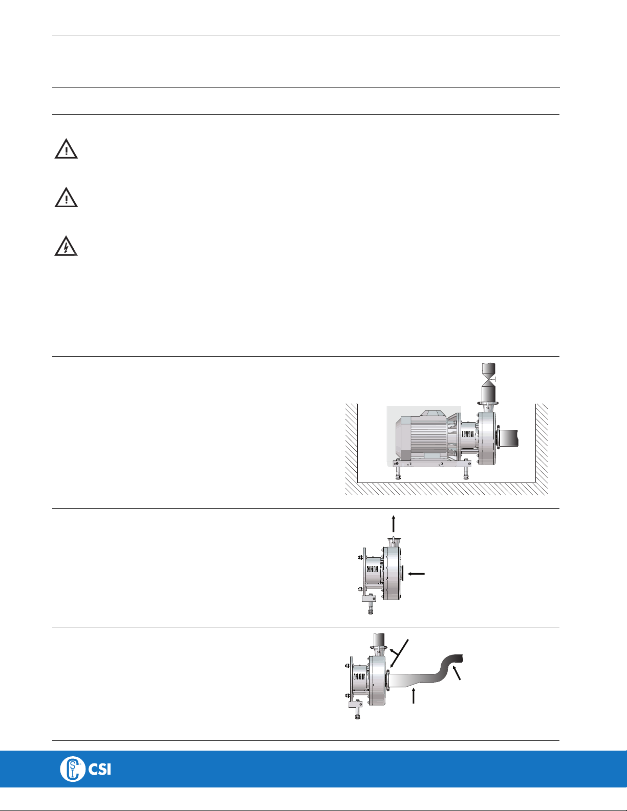
3. Installation .............................................................................................. 7
3.1. Unpacking/delivery ............................................................................... 7
3.2. Installation ......................................................................................... 8
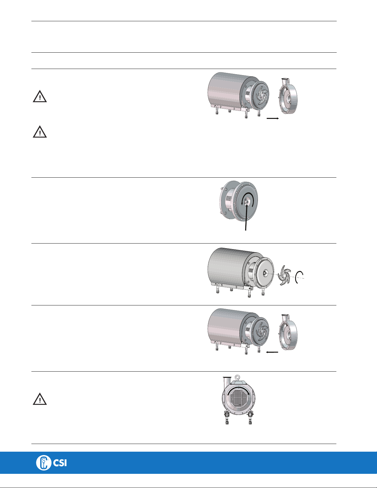
3.3. Pre-use check - pump without/with impeller screw ........................................... 10
3.4. Recycling information ............................................................................. 11
4. Operation ............................................................................................... 12
4.1. Operation/Control ................................................................................. 12
4.2. Troubleshooting ................................................................................... 14
4.3. Recommended cleaning ......................................................................... 15
5. Maintenance ........................................................................................... 17
5.1. General maintenance ............................................................................. 17
5.2. Cleaning procedure ............................................................................... 18
5.3. Dismantling of pump/shaft seals ................................................................ 19
5.4. Assembly of pump/shaft seal .................................................................... 22
6. Technical data ......................................................................................... 25
6.1. Technical data ..................................................................................... 25
6.2. Torque specifications ............................................................................. 26
6.3. Weight (kg) ........................................................................................ 26
6.4. Noise emission .................................................................................... 27
6.5. Relubrication intervals ............................................................................ 28
7. Parts list and service kits ............................................................................ 30
7.1. LKHPF Filtration centrifugal pump for high inlet pressure ..................................... 30
7.2. LKHPF - Wet end ................................................................................. 31
7.3. LKHPF - Motor-dependent parts ............................................................... 33
7.4. LKHPF - Shaft seals .............................................................................. 35
3

1 EC Declaration of Conformity
Revision of Declaration of Conformity 2009-12-29
The Designated Company
Alfa Laval Kolding A/S
Company Name
Albuen 31, DK-6000 Kolding, Denmark
Address
+45 79 32 22 00
Phone No.
hereby declare that
Pump
Designation
LKHPF-10, LKHPF-20, LKHPF-25, LKHPF-35, LKHPF-40, LKHPF-45, LKHPF-50, LKHPF-60, LKHPF-70
Type
From serial number 10.000 to 1.000.000
is in conformity with the following directive with amendments:
- Machinery Directive 2006/42/EC
The person authorised to compile the technical file is the signer of this document
Global Product Quality Manager
Pump, Valves, Fittings and Tank Equipment Lars Kruse Andersen
Title Name
Kolding 2013-12-03
Place Date Signature
4

2 Safety
Unsafe practices and other important information are emphasised in this manual.
Warnings are indicated by means of special signs.
A
A
l
l
w
w
a
a
y
y
s
s
r
r
e
e
a
a
d
d
t
t
h
h
e
e
m
m
a
a
n
n
u
u
a
a
l
l
b
b
e
e
f
f
o
o
r
r
e
e
u
u
s
s
i
i
n
n
g
g
t
t
h
h
e
e
p
p
u
u
m
m
p
p
!
!
2.1 Important information
W
W
A
A
R
R
N
N
I
I
N
N
G
G
Indicates that special procedures must be followed to avoid serious personal injury.
C
C
A
A
U
U
T
T
I
I
O
O
N
N
Indicates that special procedures must be followed to avoid damage to the pump.
N
N
O
O
T
T
E
E
Indicates important information to simplify or clarify procedures.
2.2 Warning signs
G
G
e
e
n
n
e
e
r
r
a
a
l
l
w
w
a
a
r
r
n
n
i
i
n
n
g
g
:
:
D
D
a
a
n
n
g
g
e
e
r
r
o
o
u
u
s
s
e
e
l
l
e
e
c
c
t
t
r
r
i
i
c
c
a
a
l
l
v
v
o
o
l
l
t
t
a
a
g
g
e
e
:
:
C
C
a
a
u
u
s
s
t
t
i
i
c
c
a
a
g
g
e
e
n
n
t
t
s
s
:
:
5

2 Safety
All warnings in the manual are summarised on this page.
Pay special attention to the instructions below so that serious personal injury and/or damage to the pump are avoided.
2.3 Safety precautions
I
I
n
n
s
s
t
t
a
a
l
l
l
l
a
a
t
t
i
i
o
o
n
n
:
:
A
A
l
l
w
w
a
a
y
y
s
s
read the technical data thoroughly. (See chapter 6 Technical data) !
A
A
l
l
w
w
a
a
y
y
s
s
use a lifting crane when handling the pump.
P
P
u
u
m
m
p
p
w
w
i
i
t
t
h
h
o
o
u
u
t
t
i
i
m
m
p
p
e
e
l
l
l
l
e
e
r
r
s
s
c
c
r
r
e
e
w
w
:
:
A
A
l
l
w
w
a
a
y
y
s
s
remove the impeller before checking the direction of rotation.
N
N
e
e
v
v
e
e
r
r
start the pump if the impeller is fitted and the pump casing is removed.
P
P
u
u
m
m
p
p
w
w
i
i
t
t
h
h
I
I
m
m
p
p
e
e
l
l
l
l
e
e
r
r
s
s
c
c
r
r
e
e
w
w
:
:
N
N
e
e
v
v
e
e
r
r
start in the wrong direction of rotation with liquid in the pump.
A
A
l
l
w
w
a
a
y
y
s
s
have the pump electrically connected by authorised personnel.
A
A
l
l
w
w
a
a
y
y
s
s
have the pump electrically connected by authorised personnel. (See the motor instructions)
O
O
p
p
e
e
r
r
a
a
t
t
i
i
o
o
n
n
:
:
A
A
l
l
w
w
a
a
y
y
s
s
read the technical data thoroughly. (See chapter 6 Technical data) !
N
N
e
e
v
v
e
e
r
r
touch the pump or the pipelines when pumping hot liquids or when sterilising.
N
N
e
e
v
v
e
e
r
r
run the pump with both the suction side and the pressure side blocked.
N
N
e
e
v
v
e
e
r
r
run the pump when partially installed or not completely assembled
N
N
e
e
c
c
e
e
s
s
s
s
a
a
r
r
y
y
precautions must be taken if leakage occurs as this can lead to hazardous situations.
A
A
l
l
w
w
a
a
y
y
s
s
handle lye and acid with great care.
N
N
e
e
v
v
e
e
r
r
use the pump for products not mentioned in the Alfa Laval pump selection program.
The Alfa Laval pump selection program can be acquired from your local Alfa Laval sales company.
M
M
a
a
i
i
n
n
t
t
e
e
n
n
a
a
n
n
c
c
e
e
:
:
A
A
l
l
w
w
a
a
y
y
s
s
read the technical data thoroughly. (See chapter 6 Technical data) !
N
N
e
e
v
v
e
e
r
r
service the pump when it is hot.
N
N
e
e
v
v
e
e
r
r
service the pump if pressurized.
A
A
l
l
w
w
a
a
y
y
s
s
use Alfa Laval genuine spare parts.
M
M
o
o
t
t
o
o
r
r
s
s
w
w
i
i
t
t
h
h
g
g
r
r
e
e
a
a
s
s
e
e
n
n
i
i
p
p
p
p
l
l
e
e
s
s
:
:
Always lubricate according to motor manufactures recommended procedures.
Always locate and remove grease vent plugs, if provided, prior to adding grease.
Always check motor nameplate for grease type and lubrication intervals.
A
A
l
l
w
w
a
a
y
y
s
s
disconnect the power supply when servicing the pump.
T
T
r
r
a
a
n
n
s
s
p
p
o
o
r
r
t
t
a
a
t
t
i
i
o
o
n
n
:
:
T
T
r
r
a
a
n
n
s
s
p
p
o
o
r
r
t
t
a
a
t
t
i
i
o
o
n
n
o
o
f
f
t
t
h
h
e
e
p
p
u
u
m
m
p
p
o
o
r
r
t
t
h
h
e
e
p
p
u
u
m
m
p
p
u
u
n
n
i
i
t
t
:
:
N
N
e
e
v
v
e
e
r
r
lift or elevate the pump in any way other than as described in this manual
A
A
l
l
w
w
a
a
y
y
s
s
drain the pump head and accessories of any liquid
A
A
l
l
w
w
a
a
y
y
s
s
ensure that no leakage of lubricants can occur
A
A
l
l
w
w
a
a
y
y
s
s
transport the pump in its upright position
A
A
l
l
w
w
a
a
y
y
s
s
ensure that the unit is securely fixed during transportation
A
A
l
l
w
w
a
a
y
y
s
s
use original packaging or similar during transportation
6

3 Installation
3.1 Unpacking/delivery
S
S
t
t
e
e
p
p
1
1
Always use a lifting crane when handling the pump (see technical
data).
C
C
A
A
U
U
T
T
I
I
O
O
N
N
Alfa Laval cannot be held responsible for incorrect unpacking.
W
W
A
A
R
R
N
N
I
I
N
N
G
G
:
:
Be aware that certain pump configurations can tilt, and thereby
cause injuries to feet or fingers. The pump should be supported
underneath the adaptor, when not installed in the process line.
C
C
h
h
e
e
c
c
k
k
t
t
h
h
e
e
d
d
e
e
l
l
i
i
v
v
e
e
r
r
y
y
f
f
o
o
r
r
:
:
1. Complete pump.
2. Delivery note.
3. Motor instructions.
S
S
t
t
e
e
p
p
2
2
Remove any packing materials from the inlet and the outlet.
Avoid damaging the inlet and the outlet.
Avoid damaging the connections for flushing liquid, if supplied.
TD 252-004
Remove
packing
materials!
S
S
t
t
e
e
p
p
3
3
Inspect the pump for visible transport damage.
Inspect!
TD 252-004
S
S
t
t
e
e
p
p
4
4
Always remove the shroud, if fitted, before lifting the pump.
Remove the shroud before lifting!
TD 252-005
7

3 Installation
Read the instructions carefully and pay special attention to the warnings! Always check the pump before operation.
- See the pre-use check in section 3.3 Pre-use check - pump without/with impeller screw.
The larger pumps sizes are very heavy. Alfa Laval therefore recommends the use of a lifting crane when handling the pump.
3.2 Installation
S
S
t
t
e
e
p
p
1
1
A
A
l
l
w
w
a
a
y
y
s
s
read the technical data thoroughly. (See chaper 6 Technical data)
A
A
l
l
w
w
a
a
y
y
s
s
use a lifting crane when handling the pump. (See chaper 6 Technical data)
A
A
l
l
w
w
a
a
y
y
s
s
have the pump electrically connected by authorised personnel. (see the motor instructions).
C
C
A
A
U
U
T
T
I
I
O
O
N
N
Alfa Laval cannot be held responsible for incorrect installation.
W
W
A
A
R
R
N
N
I
I
N
N
G
G
:
:
Alfa Laval recommends the installation of lockable repair breaker. If the repair breaker is to be used as an emergency stop,
the colours of the repair breaker must be red and yellow.
S
S
t
t
e
e
p
p
2
2
Ensure that there is sufficient clearance around the pump (min.
0.5 m) (1.64”).
C
C
a
a
u
u
t
t
i
i
o
o
n
n
:
:
The pump does not prevent back flow when intentionally or
unintentionally stopped. If back flow can cause any hazardous
situations, precautions must be taken e.g. a check valve is to be
installed in the system preventing that described above.
TD 252-006
S
S
t
t
e
e
p
p
3
3
Check that the flow direction is correct.
O: Outlet
I: Inlet
TD 252-007
I
O
Correct!
S
S
t
t
e
e
p
p
4
4
1. Ensure that the pipelines are routed correctly.
2. Ensure that the connections are tight.
Remember seal rings!
TD 252-008
Few bends
Correct!
8

3 Installation
Read the instructions carefully and pay special attention to the warnings! Always check the pump before operation.
- See the pre-use check in section 3.3 Pre-use check - pump without/with impeller screw.
The larger pumps sizes are very heavy. Alfa Laval therefore recommends the use of a lifting crane when handling the pump.
S
S
t
t
e
e
p
p
5
5
Avoid stress on the pump.
Piping system must be self-surpported.
Pay special attention to:
- Vibrations.
- Thermal expansion of the tubes.
- Excessive welding.
- Overloading of the pipelines.
TD 252-009
N
N
o
o
t
t
e
e
In case of shaft seal leakage, the media will drip from the slot in the bottom of the adaptor. In case of shaft seal leakage, Alfa
Laval recommends putting a drip tray underneath the slot for collecting the leakage.
9

3 Installation
Study the instructions carefully and pay special attention to the warnings!
LKH-5 to LKH-60 are supplied without impeller screw as standard but this can be supplied.
Check the direction of rotation of the impeller before operation.
- See the indication label on the pump.
3.3 Pre-use check - pump without/with impeller screw
S
S
t
t
e
e
p
p
1
1
P
P
u
u
m
m
p
p
w
w
i
i
t
t
h
h
o
o
u
u
t
t
i
i
m
m
p
p
e
e
l
l
l
l
e
e
r
r
s
s
c
c
r
r
e
e
w
w
A
A
l
l
w
w
a
a
y
y
s
s
remove the impeller before checking the direction of
rotation.
N
N
e
e
v
v
e
e
r
r
start the pump if the impeller is fitted and the pump casing
is removed.
1. Remove cap nuts (28), washers (29) and pump casing (45).
2. Remove impeller (39) (see also the instruction in section 5.4
Assembly of pump/shaft seal).
TD 252-010
S
S
t
t
e
e
p
p
2
2
1. Start and stop the motor momentarily.
2. Ensure that the direction of rotation of the stub shaft (9) is
anti-clockwise as viewed from the inlet side.
See the indication label!
Correct!
TD 252-011
Stub shaft
S
S
t
t
e
e
p
p
3
3
Fit and tighten impeller (39).
TD 252-012
S
S
t
t
e
e
p
p
4
4
1. Fit pump casing (45).
2. Fit washers (29) and cap nuts (28) and tighten.
Note: Cap nuts must be tightened according to the torque
values specified in section 6 Technical data
TD 252-013
S
S
t
t
e
e
p
p
1
1
P
P
u
u
m
m
p
p
w
w
i
i
t
t
h
h
i
i
m
m
p
p
e
e
l
l
l
l
e
e
r
r
s
s
c
c
r
r
e
e
w
w
N
N
e
e
v
v
e
e
r
r
start in the wrong direction of rotation with liquid in the
pump.
1. Start and stop the motor momentarily.
2. Ensure that the direction of rotation of the motor fan is
clockwise as viewed from the rear end of the motor.
See the indication label!
Correct
TD 252-014 View from rear end of
motor
10

3 Installation
3.4 Recycling information
•
•
U
U
n
n
p
p
a
a
c
c
k
k
i
i
n
n
g
g
- Packing material consists of wood, plastics, cardboard boxes and in some cases metal straps.
- Wood and cardboard boxes can be re-used, recycled or used for energy recovery.
- Plastics should be recycled or burnt at a licensed waste incineration plant.
- Metal straps should be sent for material recycling.
•
•
M
M
a
a
i
i
n
n
t
t
e
e
n
n
a
a
n
n
c
c
e
e
- During maintenance, oil and wearing parts in the machine are replaced.
- All metal parts should be sent for material recycling.
- Worn out or defective electronic parts should be sent to a licensed handler for material recycling.
- Oil and all non-metal wearing parts must be disposed of in accordance with local regulations.
•
•
S
S
c
c
r
r
a
a
p
p
p
p
i
i
n
n
g
g
- At the end of use, the equipment must be recycled according to the relevant, local regulations. Besides the equipment itself,
any hazardous residues from the process liquid must be considered and disposed of in a proper manner. When in doubt, or
in the absence of local regulations, please contact your local Alfa Laval sales company.
11

4 Operation
Read the instructions carefully and pay special attention to the warnings!
4.1 Operation/Control
S
S
t
t
e
e
p
p
1
1
A
A
l
l
w
w
a
a
y
y
s
s
read the technical data thoroughly. See chapter 6
Technical data
C
C
A
A
U
U
T
T
I
I
O
O
N
N
Alfa Laval cannot be held responsible for incorrect
operation/control.
S
S
t
t
e
e
p
p
2
2
N
N
e
e
v
v
e
e
r
r
touch the pump or the pipelines when pumping hot liquids
or when sterilising.
D
D
a
a
n
n
g
g
e
e
r
r
o
o
f
f
b
b
u
u
r
r
n
n
s
s
!
!
TD 252-015
S
S
t
t
e
e
p
p
3
3
N
N
e
e
v
v
e
e
r
r
run the pump with both the suction side and the pressure
side blocked.
D
D
a
a
n
n
g
g
e
e
r
r
o
o
f
f
e
e
x
x
p
p
l
l
o
o
s
s
i
i
o
o
n
n
!
!
!
TD 252-016
S
S
e
e
e
e
t
t
h
h
e
e
w
w
a
a
r
r
n
n
i
i
n
n
g
g
l
l
a
a
b
b
e
e
l
l
!
!
S
S
t
t
e
e
p
p
4
4
C
C
A
A
U
U
T
T
I
I
O
O
N
N
The shaft seal must not run dry.
C
C
A
A
U
U
T
T
I
I
O
O
N
N
N
N
e
e
v
v
e
e
r
r
throttle the inlet side.
D
D
o
o
n
n
o
o
t
t
a
a
l
l
l
l
o
o
w
w
t
t
o
o
r
r
u
u
n
n
d
d
r
r
y
y
Correct!
TD 252-017
Wrong
12

4 Operation
Read the instructions carefully and pay special attention to the warnings!
S
S
t
t
e
e
p
p
5
5
F
F
l
l
u
u
s
s
h
h
e
e
d
d
s
s
h
h
a
a
f
f
t
t
s
s
e
e
a
a
l
l
:
:
1. Connect the inlet of the flushing liquid correctly
(ø6 tube).
2. Regulate the water supply correctly.
3. Observe the steam data.
O: Outlet
I: Inlet
Correct!
I
O
TD 252-018_1
Tmax = 100°C
Pmax = 1 bar (flush seal)
Pmax = 5 bar (double
mechanical seal)
S
S
t
t
e
e
p
p
6
6
C
C
o
o
n
n
t
t
r
r
o
o
l
l
:
:
Reduce the capacity and the power consumption by means of:
- Throttling the pressure side of the pump.
- Reducing the impeller diameter.
- Reducing the speed of the motor.
TD 252-019
Throttling!
13

4 Operation
Pay attention to possible faults.
Read the instructions carefully.
4.2 Troubleshooting
N
N
O
O
T
T
E
E
!
!
Study the maintenance instructions carefully before replacing worn parts. - See section 5.1 General maintenance
P
P
r
r
o
o
b
b
l
l
e
e
m
m
C
C
a
a
u
u
s
s
e
e
/
/
r
r
e
e
s
s
u
u
l
l
t
t
R
R
e
e
m
m
e
e
d
d
y
y
Overloaded motor - Pumping of viscous liquids - Larger motor or smaller impeller
- Pumping of high density liquids
- Low outlet pressure (counter pressure) - Higher counter pressure (throttling)
- Lamination of precipitates from the
liquid
- Frequent cleaning
Cavitation:
- Damage - Low inlet pressure - Increase the inlet pressure
- Pressure reduction (sometimes to
zero)
- High liquid temperature - Reduce the liquid temperature
- Increase in noise level - Reduce the pressure drop before the
pump
- Reduce speed
Leaking shaft seal - Dry run Replace:
All wearing parts
- Incorrect rubber grade If necessary:
- Change rubber grade
- Abrasive particles in the liquid - Select stationary and rotating seal ring
in silicon carbide/silicon carbide
Leaking O-ring seals Incorrect rubber grade Change rubber grade
14

4 Operation
The pump is designed for cleaning in place (CIP). CIP = Cleaning In Place.
Read the instructions carefully and pay special attention to the warnings!
NaOH = Caustic soda.
HNO3= Nitric acid.
4.3 Recommended cleaning
S
S
t
t
e
e
p
p
1
1
A
A
l
l
w
w
a
a
y
y
s
s
handle lye and acid with great care.
D
D
a
a
n
n
g
g
e
e
r
r
,
,
c
c
a
a
u
u
s
s
t
t
i
i
c
c
!
!
Always wear rubber
gloves!
Always wear protective
goggles!
S
S
t
t
e
e
p
p
2
2
N
N
e
e
v
v
e
e
r
r
touch the pump or the pipelines when sterilising.
D
D
a
a
n
n
g
g
e
e
r
r
o
o
f
f
b
b
u
u
r
r
n
n
s
s
!
!
TD 252-015
S
S
t
t
e
e
p
p
3
3
E
E
x
x
a
a
m
m
p
p
l
l
e
e
s
s
o
o
f
f
c
c
l
l
e
e
a
a
n
n
i
i
n
n
g
g
a
a
g
g
e
e
n
n
t
t
s
s
:
:
Use clean water, free from chlorides.
1. 1% by weight NaOH at 70°C (158°F).
1 kg (2.2 lb) +100 l (26.4 gal) = Cleaning agent.
NaOH water
2.2 l (0.6 gal) +100 l (26.4 gal) = Cleaning agent.
33% NaOH water
2. 0.5% by weight HNO3at 70°C (158°F).
0.7 l (0.2 gal) +100 l (26.4 gal) = Cleaning agent.
53% HNO3water
1. Avoid excessive concentration
of the cleaning agent
⇒Dose gradually!
2. Adjust the cleaning flow to the
process.
Sterilisation of milk/viscous
liquids
⇒Increase the cleaning flow!
15

4 Operation
The pump is designed for cleaning in place (CIP). CIP = Cleaning In Place.
Read the instructions carefully and pay special attention to the warnings!
NaOH = Caustic soda.
HNO3= Nitric acid.
S
S
t
t
e
e
p
p
4
4
!
A
A
l
l
w
w
a
a
y
y
s
s
rinse well with clean water after using a cleaning agent.
N
N
O
O
T
T
E
E
The cleaning agents must be stored/disposed of in accordance
with current regulations/directives.
A
A
l
l
w
w
a
a
y
y
s
s
r
r
i
i
n
n
s
s
e
e
!
!
Clean water Cleaning agent
N
N
O
O
T
T
E
E
:
:
If pumps are sterilised using steam, standard 3A requires the process system to be designed to automatically shut down if the
product pressure in the system becomes less than that of the atmosphere and it cannot be started until the system is re-sterilised.
16

5 Maintenance
Maintain the pump carefully. Read the instructions carefully and pay special attention to the warnings!
Always keep spare shaft seals and rubber seals in stock.
See separate motor instructions.
Check the pump for smooth operation after service.
5.1 General maintenance
S
S
t
t
e
e
p
p
1
1
A
A
l
l
w
w
a
a
y
y
s
s
read the technical data thoroughly. (See chaper 6
Technical data)
A
A
l
l
w
w
a
a
y
y
s
s
disconnect the power supply when servicing the pump.
N
N
O
O
T
T
E
E
All scrap must be stored/discharged in accordance with current
rules/directives.
S
S
t
t
e
e
p
p
2
2
N
N
e
e
v
v
e
e
r
r
service the pump when it is hot.
D
D
a
a
n
n
g
g
e
e
r
r
o
o
f
f
b
b
u
u
r
r
n
n
s
s
!
!
TD 252-015
S
S
t
t
e
e
p
p
3
3
N
N
e
e
v
v
e
e
r
r
service the pump with the pump and pipelines under
pressure.
C
C
A
A
U
U
T
T
I
I
O
O
N
N
Fit the electrical connections correctly if they have been removed
from the motor during service. (see 3.3 Pre-use check - pump
without/with impeller screw)
C
C
A
A
U
U
T
T
I
I
O
O
N
N
Pay special attention to the warnings!
TD 252-020
Atmospheric pressure
required!
S
S
t
t
e
e
p
p
4
4
R
R
e
e
c
c
o
o
m
m
m
m
e
e
n
n
d
d
e
e
d
d
s
s
p
p
a
a
r
r
e
e
p
p
a
a
r
r
t
t
s
s
:
:
Order service kits from the service kits list
(see chapter 7 Parts list and service kits).
O
O
r
r
d
d
e
e
r
r
i
i
n
n
g
g
s
s
p
p
a
a
r
r
e
e
p
p
a
a
r
r
t
t
s
s
Contact your local Alfa Laval sales company.
N
N
o
o
t
t
e
e
:
:
If the pump is supplied with FEP O-rings, Alfa Laval recommends replacing the casing O-ring during pump maintenance.
17

5 Maintenance
Maintain the pump carefully. Read the instructions carefully and pay special attention to the warnings!
Always keep spare shaft seals and rubber seals in stock.
See separate motor instructions.
Check the pump for smooth operation after service.
NOTE! Read the maintenance instructions carefully before replacing worn parts. - See section 5.1 General maintenance
S
S
h
h
a
a
f
f
t
t
s
s
e
e
a
a
l
l
R
R
u
u
b
b
b
b
e
e
r
r
s
s
e
e
a
a
l
l
s
s
Motor bearings
Preventive maintenance R
R
e
e
p
p
l
l
a
a
c
c
e
e
a
a
f
f
t
t
e
e
r
r
1
1
2
2
m
m
o
o
n
n
t
t
h
h
s
s
:
:
(one-shift) Complete shaft seal
Replace when replacing the
shaft seal
Maintenance after leakage
(leakage normally starts slowly)
R
R
e
e
p
p
l
l
a
a
c
c
e
e
a
a
t
t
t
t
h
h
e
e
e
e
n
n
d
d
o
o
f
f
t
t
h
h
e
e
d
d
a
a
y
y
:
:
Complete shaft seal
Replace when replacing the
shaft seal
Planned maintenance - Regular inspection for
leakage and smooth
operation
- Keep a record for the pump
- Use the statistics for
inspection planning
purposes
R
R
e
e
p
p
l
l
a
a
c
c
e
e
a
a
f
f
t
t
e
e
r
r
l
l
e
e
a
a
k
k
a
a
g
g
e
e
:
:
Complete shaft seal
Replace when replacing the
shaft seal
Annual inspection is
recommended
- Replace complete bearing
if worn
- Ensure that the bearing is
axially locked (See motor
instructions)
Lubrication B
B
e
e
f
f
o
o
r
r
e
e
f
f
i
i
t
t
t
t
i
i
n
n
g
g
Lubricate the O-rings with
silicone grease or silicone oil
B
B
e
e
f
f
o
o
r
r
e
e
f
f
i
i
t
t
t
t
i
i
n
n
g
g
Silicone grease or silicone oil
See section 6.5 Relubrication
intervals
P
P
r
r
e
e
-
-
u
u
s
s
e
e
c
c
h
h
e
e
c
c
k
k
C
C
A
A
U
U
T
T
I
I
O
O
N
N
!
!
Fit the electrical connections correctly if they have been removed from the motor during service. (See 3.3 Pre-use check -
pump without/with impeller screw).
P
P
a
a
y
y
s
s
p
p
e
e
c
c
i
i
a
a
l
l
a
a
t
t
t
t
e
e
n
n
t
t
i
i
o
o
n
n
t
t
o
o
w
w
a
a
r
r
n
n
i
i
n
n
g
g
s
s
!
!
1. Start and stop the motor momentarily
2. Ensure that the pump operates smoothly.
5.2 Cleaning procedure
C
C
l
l
e
e
a
a
n
n
i
i
n
n
g
g
p
p
r
r
o
o
c
c
e
e
d
d
u
u
r
r
e
e
f
f
o
o
r
r
s
s
o
o
i
i
l
l
e
e
d
d
i
i
m
m
p
p
e
e
l
l
l
l
e
e
r
r
s
s
c
c
r
r
e
e
w
w
t
t
a
a
p
p
p
p
e
e
d
d
h
h
o
o
l
l
e
e
:
:
1. Remove stub shaft (9) in accordance with section 5.3 of the Service manual.
2. Submerge and soak the stub shaft for 5 minutes in COP tank with 2% caustic wash
3. Scrub the blind tapped impeller screw hole vigorously by plunging a clean 1/2” diameter sanitary bristle pipe brush in and out
of the hole for two minutes while submerged.
4. Soak Stub Shaft (9) in acid sanitiser for 5 minutes, then scrub the blind tapped hole as described in step 3 above.
5. Rinse well with clean water and blow-dry the blind tapped hole with clean air.
6. Swab test the inside of the tapped hole to determine cleanliness.
7. Should the swab test fail, repeat steps 2 to 6 above until the swab test is passed.
Should swab testing continue to fail, or time is of the essence, install a new (spare) stub shaft (9).
18

5 Maintenance
Read the instructions carefully. The items refer to the parts list and service kits section.
Handle scrap correctly.
: Relates to the shaft seal.
5.3 Dismantling of pump/shaft seals
S
S
t
t
e
e
p
p
1
1
1. Unscrew cap nuts (28) and remove washers (29) and pump
casing (45).
TD 252-021
S
S
t
t
e
e
p
p
2
2
Remove screw (14) and safety guard (15).
TD 252-022
S
S
t
t
e
e
p
p
3
3
F
F
l
l
u
u
s
s
h
h
e
e
d
d
s
s
h
h
a
a
f
f
t
t
s
s
e
e
a
a
l
l
:
:
Unscrew fittings (23) using a spanner.
TD 252-023
S
S
t
t
e
e
p
p
4
4
1. Remove impeller screw (41), if fitted, and pull off O-ring (42).
2. Remove impeller (39/40). If necessary, loosen the impeller by
knocking gently on the impeller vanes.
Counterhold
with a
screwdriver!
TD 252-024
If necessary!
S
S
t
t
e
e
p
p
5
5
Pull out impeller (39/40) and the rotating part of the shaft seal.
TD 252-025
S
S
t
t
e
e
p
p
6
6
Remove space ring (33) and the rotating part of the shaft seal from
impeller (39)/(40).
TD 252-026
19

5 Maintenance
Read the instructions carefully. The items refer to the parts list and service kits section.
Handle scrap correctly.
: Relates to the shaft seal.
S
S
t
t
e
e
p
p
7
7
Separate rotating seal ring (34), quad rings (35, 38), support ring
(36), guide ring (37) and washer (37) from rotating seal housing (37).
TD 252-027
34
35
36
37
38
S
S
t
t
e
e
p
p
8
8
1. Unscrew nuts (19) and remove washers (20) and back plate
(30).
2. Pull off joint ring (43) from the back plate.
TD 252-028
S
S
t
t
e
e
p
p
9
9
1. Pull out stationary seal ring (32).
2. Remove O-ring (31) from the stationary seal ring.
TD 252-029
S
S
t
t
e
e
p
p
1
1
0
0
F
F
l
l
u
u
s
s
h
h
e
e
d
d
s
s
h
h
a
a
f
f
t
t
s
s
e
e
a
a
l
l
1. Remove screws (22) and seal housing (21).
2. Pull out lip seal (24) and O-ring (26) from the seal housing.
3. Slide off sleeve (27) from stub shaft (9).
4. Remove O-ring (25) from the sleeve. TD 252-030
S
S
t
t
e
e
p
p
1
1
1
1
1. Remove shroud (2).
2. Unscrew nuts (7) and remove washers (6), screws (18) and
adaptor (17).
TD 252-052
S
S
t
t
e
e
p
p
1
1
2
2
1. Loosen screws (13).
2. Slide off stub shaft (9) together with compression rings (12a+b).
TD 252-053
20
Table of contents
Other CSI Water Pump manuals
Popular Water Pump manuals by other brands

Whale
Whale AK1316 Installation and operation manual

BLUCHER
BLUCHER CP 700E instruction manual

FLOJET
FLOJET 3426 series user manual

Grundfos
Grundfos ALPHA1 B Installation and operating instructions

HEISSNER
HEISSNER HFP2500-00 Instructions for use

Armstrong
Armstrong 4600 HSC series Installation and operating instructions