CSL Eickhoff User manual

Eickhoff Diagnostic Charging Station 1 / 30 November 2015 –Issue 1.6
Eickhoff Diagnostic Charging Station
User Manual
Issue 1.6
(New Bluetooth module and Software)
Controlled Systems Limited
Ryder Close, Swadlincote, Derbyshire. DE11 9EU. England
TEL: +44 (0)1283 216231 / FAX: +44 (0)1283 552937 / sales@controlledsystemsltd.co.uk
CSL

Eickhoff Diagnostic Charging Station 2 / 30 November 2015 –Issue 1.6
Table of Contents
1Features ........................................................................................3
1.1 Eickhoff Diagnostic Charging Station Overview......................................3
1.2 Eickhoff Diagnostic Charging Station Features ......................................3
2Description.....................................................................................4
3Connections...................................................................................5
4Installation .....................................................................................7
5Operating the Diagnostic Charging Station....................................8
5.1 Powering Unit On ...................................................................................8
5.2 A Search for Bluetooth devices begins...................................................9
5.3 Select which Handsets are required.....................................................10
5.4 Screen showing connected handsets...................................................11
5.5 Testing for correct operation of handset keys.......................................12
5.6 Radio Handset Display Highlighted ......................................................13
5.7 Updating Radio Handset Software .......................................................14
5.8 Updating the Radio Handset Font Chip................................................17
5.9 Updating Radio Handset S/N and H/W Versions..................................19
5.9 Turning off a Radio Handset.................................................................21
5.10 Wire bound handset display.................................................................23
5.11 RF Power Sensor.................................................................................24
5.12 Using VNC Connectivity over Ethernet.................................................26
5.13 Updating Diagnostic Station S/W and adding new .hex Files...............26
5.14 CANBUS / MK2 Machine Radio C515184 Test ………………………....28
6Mechanical Details.......................................................................30
7Environmental..............................................................................30
8Maintenance................................................................................30
9Waste Removal Information.........................................................30

Eickhoff Diagnostic Charging Station 3 / 30 November 2015 –Issue 1.6
1 Features
1.1 Eickhoff Diagnostic Charging Station Overview
15” 1024 x 768 SVGA colour display with touch screen
Six radio handset charging ports
Wire bound connector for testing wire bound handset
12 Volt auxiliary supply output terminals
Integrated Bluetooth RF power meter
Network connectivity via 10/100 Ethernet port
CANBUS test port
USB port
1.2 Eickhoff Diagnostic Charging Station Features
Search for radio handsets and display up to six on the colour display. The
radio handsets need to be on charge for the search to be successful.
Charge up to six radio handsets at once.
Update software versions in handsets and receiver.
Update fonts.
Update serial number and H/W version
VNC connectivity available over Ethernet.
Update future diagnostic charging station software versions using USB or
Ethernet (VNC).
Radio handset display shows:
Online status
Battery status
Battery voltage, charging current and temperature
Serial number
Bluetooth address
Software version and (hardware version)

Eickhoff Diagnostic Charging Station 4 / 30 November 2015 –Issue 1.6
2 Description
The internal power supply unit will operate correctly with an external supply
between 90 –264 volts and 47 –63 Hz
The Diagnostic Station is powered by an Intel core2 duo processor
incorporated inside the unit.
The unit is equipped with a touch screen for easy onsite operation, negating
the need to use a keyboard or mouse for every day testing.
Radio handsets are detected during a search when they are on charge.

Eickhoff Diagnostic Charging Station 5 / 30 November 2015 –Issue 1.6
3 Connections
The external connections on the right hand side of the unit are shown below:
The external connections on the left hand side of the unit are shown below:
RF Power meter connector
BT antenna
12v DC output
Ethernet port
CANBUS ‘D’ connector
USB port
Radio Handset charging connectors
Wire bound handset
socket
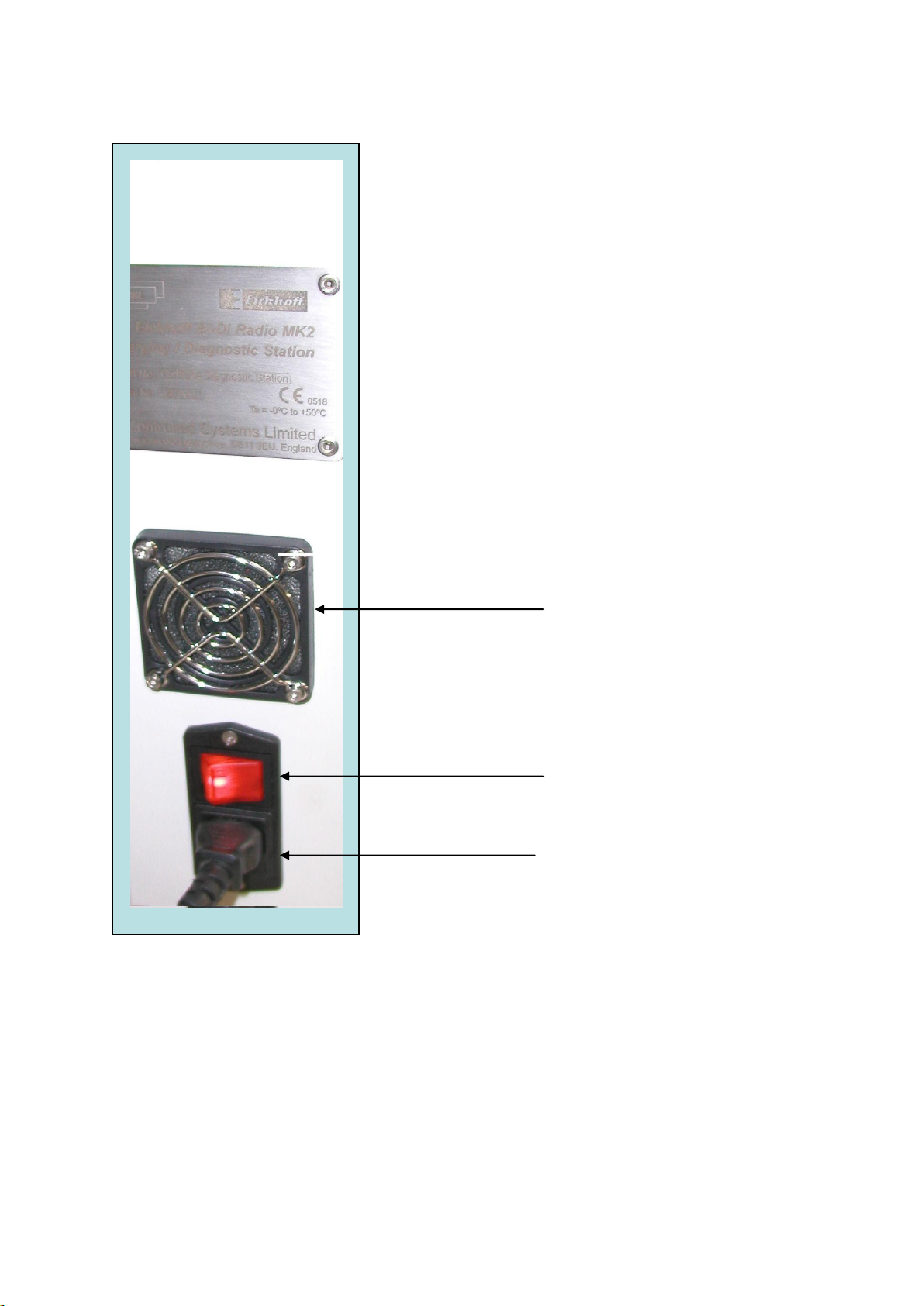
Eickhoff Diagnostic Charging Station 6 / 30 November 2015 –Issue 1.6
Cooling Fan
ON / OFF Switch
Power IEC Socket
(Fuse Holder Below)

Eickhoff Diagnostic Charging Station 7 / 30 November 2015 –Issue 1.6
4 Installation
The Diagnostic Station is only to be installed in a clean dry room and is
NOT intended for external use.
The unit is NOT designed to be used in hazardous areas
The parameters of the external power supply must fall within the range
detailed in “Description” above. The unit must be connected to earth.
This apparatus must only be installed or replaced by a competent person.
Ventilation to and from the unit must not be restricted
The operators should be trained in the safe use of the equipment, such
that operational hazards arising from misuse are avoided.
Eickhoff Diagnostic Charging Station 8 / 30 November 2015 –Issue 1.6
5 Operating the Diagnostic Charging Station
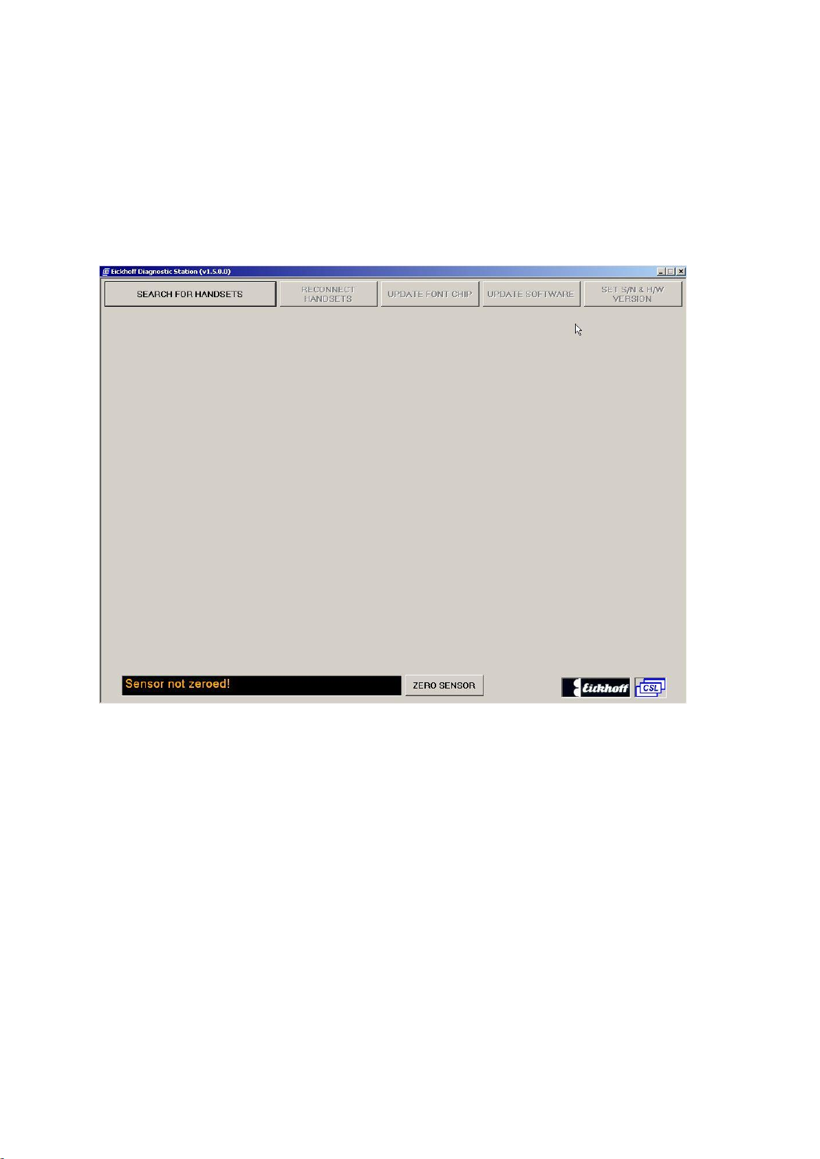
5.1 Powering Unit On
The unit is powered on by operating the switch on the left hand side of the unit and
will automatically load the diagnostic display shown below
Touch the “SEARCH FOR HANDSETS”button to start the search.
Eickhoff Diagnostic Charging Station 9 / 30 November 2015 –Issue 1.6
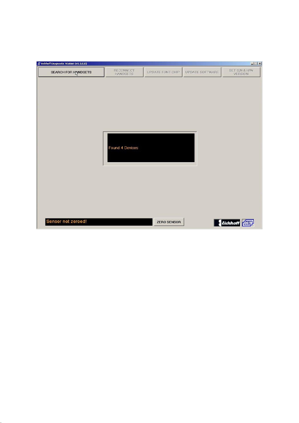
5.2 A Search for Bluetooth devices begins
The Radio Handsets must be on charge for the search to be successful. Any
Machine Radio Receiver within range of the Radio Handsets to be tested MUST be
switched OFF if the handset is logged on to it (Handsets online to a Radio Receiver
will not be found).
The search will find all discoverable Bluetooth devices including mobile phones,
laptops etc. but will then discard any that are not Radio Handsets.

Eickhoff Diagnostic Charging Station 10 / 30 November 2015 –Issue 1.6
5.3 Select which Handsets are required
On this screen simply select using the touch screen the handsets you wish to
connect. Once highlighted simply click the OK button and the unit will connect to the
specified handsets.
Eickhoff Diagnostic Charging Station 11 / 30 November 2015 –Issue 1.6
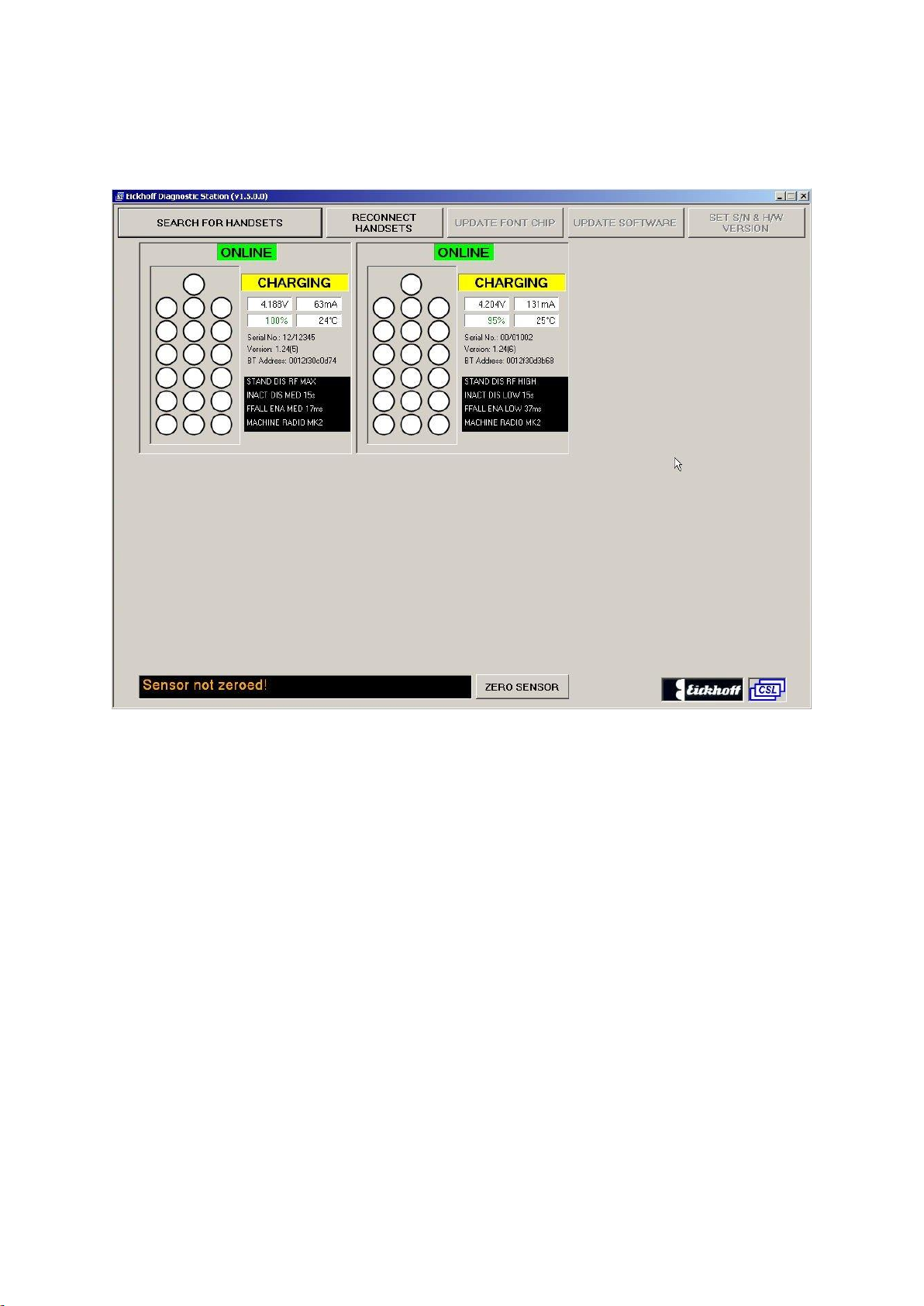
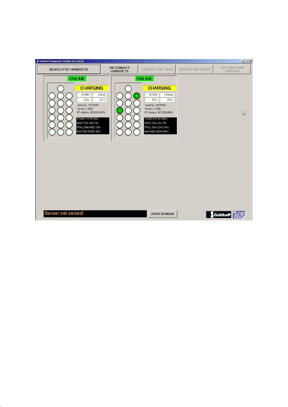
5.4 Screen showing connected handsets
A maximum of 6 radio handsets can be displayed at once.
Note:
If a wire bound handset is connected then this is reduced to 5.
Eickhoff Diagnostic Charging Station 12 / 30 November 2015 –Issue 1.6
5.5 Testing for correct operation of handset keys
The above shows 2 handset keys depressed –all keys are monitored in this way
Eickhoff Diagnostic Charging Station 13 / 30 November 2015 –Issue 1.6
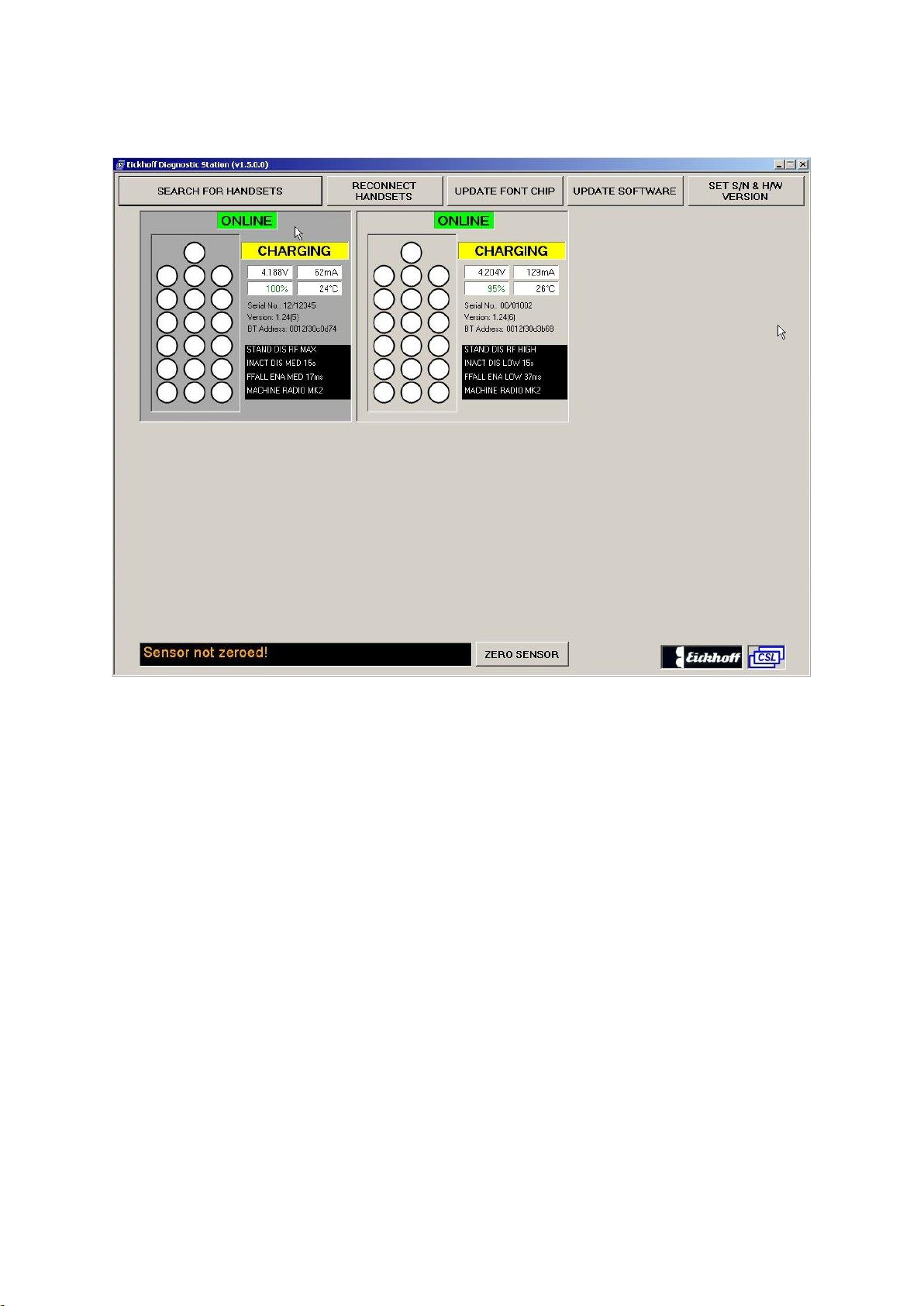
5.6 Radio Handset Display Highlighted
To highlight a “radio handset” displayed on the screen, touch the radio handset
panel. Touch the panel again to de-select it.
With a detected radio handset highlighted the “update software”, “update font chip”
and “Set S/N & H/W Version” buttons become available for that handset.

Eickhoff Diagnostic Charging Station 14 / 30 November 2015 –Issue 1.6
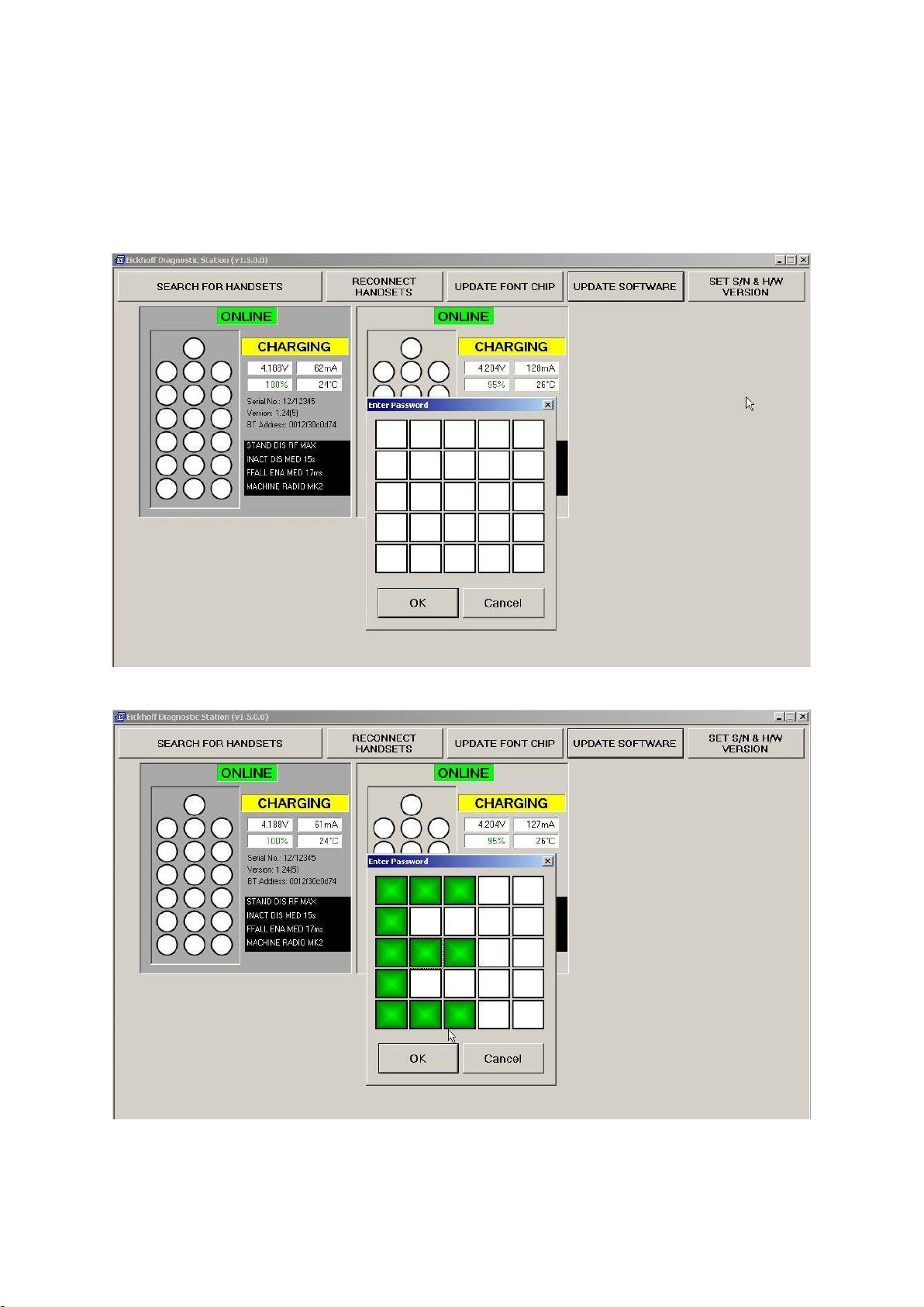
5.7 Updating Radio Handset Software
With a detected radio handset highlighted all the buttons at the top of the screen
become available for that handset. Touch “Update Software” button.
A password is then required to continue and a password box is displayed:
The “Enter Password” box.
The Password is entered by touching or selecting the squares as shown above. This
takes the form of an uppercase “E”
Eickhoff Diagnostic Charging Station 15 / 30 November 2015 –Issue 1.6
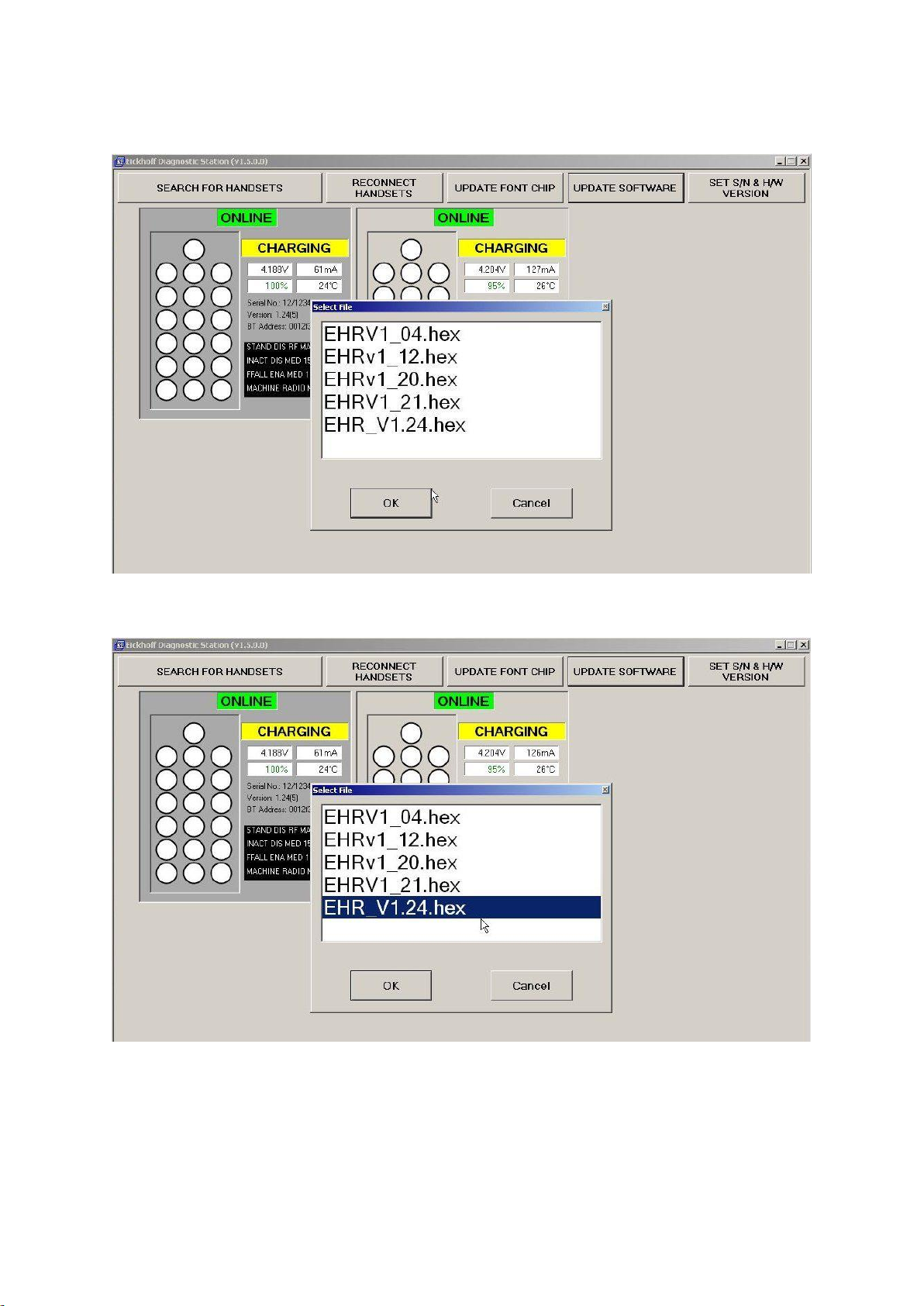
Selecting OK shows a “select file” box containing a list of available files.
Select the required file to update the radio handset
Select OK to start the update.
Eickhoff Diagnostic Charging Station 16 / 30 November 2015 –Issue 1.6
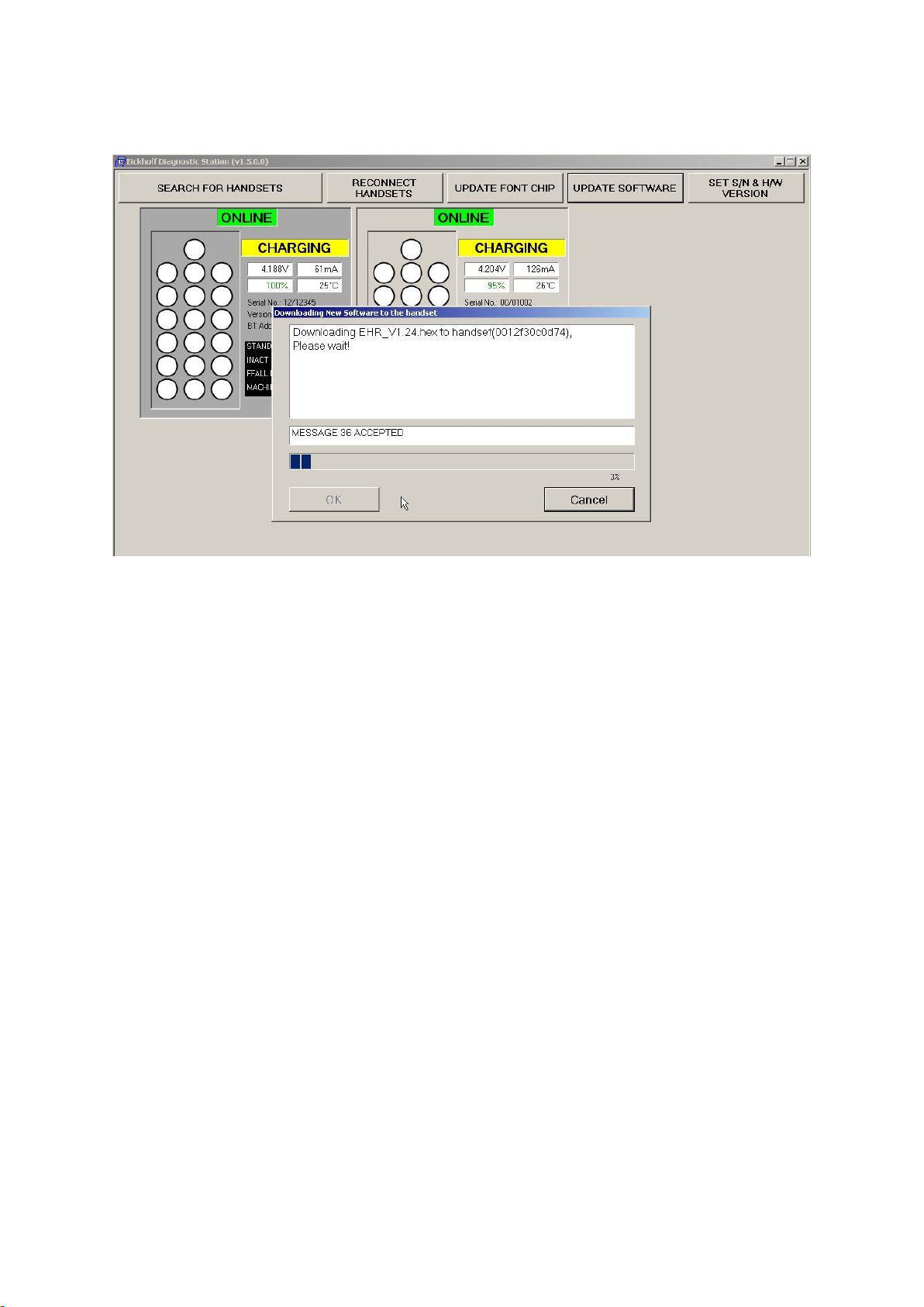
A progress bar indicates the current updating progress as shown below:
On completion touch the “OK” button to return from the update screen
Eickhoff Diagnostic Charging Station 17 / 30 November 2015 –Issue 1.6
5.8 Updating the Radio Handset Font Chip
With a detected radio handset highlighted all the buttons at the top of the screen
become available for that handset. Touch “Update Font Chip” button.
A password is then required to continue and a password box is displayed:
The “Enter Password” box is available
The Password is entered by selecting (touching) the squares as shown above. This
takes the form of an uppercase “E”

Eickhoff Diagnostic Charging Station 18 / 30 November 2015 –Issue 1.6
On selecting “OK”, the download automatically starts as shown below:
On completion touch the “OK” button to return from the update screen
Note: This update takes approximately 40 minutes to complete

Eickhoff Diagnostic Charging Station 19 / 30 November 2015 –Issue 1.6
5.9 Updating Radio Handset S/N and H/W Versions.
With a detected radio handset highlighted all the buttons at the top of the screen
become available for that handset. Touch “Set S/N & H/W Version” button.
A password is then required to continue and a password box is displayed:
The “Enter Password” box is available
The Password is entered by selecting (touching) the squares as shown above. This
takes the form of an uppercase “E”

Eickhoff Diagnostic Charging Station 20 / 30 November 2015 –Issue 1.6
On selecting “OK”, the following screen is displayed:
Use the touchpad on the right to clear or enter numbers in the field on the left which
is highlighted. Move the highlight to other fields that are required to be altered.
When happy with the entry, click the OK button to send to the handset.
Table of contents
Other CSL Batteries Charger manuals


Popular Batteries Charger manuals by other brands


CTEK
CTEK XS 800 user manual

Infinite Peripherals
Infinite Peripherals Infinea X quick start guide

Benjamin Heating products
Benjamin Heating products 81002 Operating/safety instructions

Sony
Sony BC-VC10 operating instructions

Ergotron
Ergotron Zip12 Service manual

Webasto
Webasto Next Operating and installation instructions


