ASCOM PCR Charging Rack User manual

TD 92356GB
2007-03-16/ Ver. C
Installation Guide
PCR Charging Rack

TD 92356GB
2007-03-16/ Ver. C
Installation Guide
PCR Charging Rack
Contents
1 Introduction............................................................................................................. 1
2 Safety Instructions .................................................................................................. 2
3 Installation............................................................................................................... 3
3.1 Charging Rack Master PCR-M and Extension PCR-E ........................................... 4
3.2 Examples on how to Assemble the Modules ................................................ 5
3.3 Mounting the Power Supply Module .................................................................. 6
3.4 Mounting the Charging Rack Module ................................................................ 6
3.5 Mounting Dimensions ........................................................................................ 7
3.6 Removing Covers ............................................................................................... 8
3.6.1 Power Supply Module ............................................................................ 8
3.6.2 Charging Rack Module ........................................................................... 9
3.6.3 Mounting Modules Together .................................................................... 10
4 Connection of Power Supply CR24 ...................................................................... 12
4.1 Connection of Mains Power Supply Cable (AC) ................................................ 12
4.2 Wiring Run ...................................................................................................... 15
4.3 Connection of Supply Voltage Connector ......................................................... 17
5 Maintenance Information..................................................................................... 18
5.1 Upgrading the Software ................................................................................... 18
6 Connection of Charging Rack Master PCR-M and Extension PCR-E .................. 19
7 Installation Test ..................................................................................................... 20
7.1 LED status on the PCR Charging Rack .............................................................. 20
8 Board Description, Master PCR-M and Extension PCR-E ................................... 21

TD 92356GB
2007-03-16/ Ver. C
Installation Guide
PCR Charging Rack
1
1 Introduction
Figure1.
001
Figure 1. PCR Charging Rack and Power Supply CR24.
The PCR Charging Rack is used in the On Site Paging System and in the Personal Security
System. It charges the a51 Alarm Transmitter.
The PCR Charging Rack is a modular system with three module parts; the Charging Rack
Master PCR-M module, the Charging Rack Extension PCR-E module and the Power Supply
CR24 module. Each Charging Rack (both Master PCR-M and Extension PCR-E) charges six
portables.
IMPORTANT: Power Supply CR24 is the only power supply that can be used together
with the PCR Charging Rack.
PCR Charging Rack Power Supply CR24
Supply voltage: 5 V 5V 12A max
Current consumption
(normal operation)
100 mA (Master PCR-M)
35 mA (Extension PCR-E)
Max current consumption: 4A (fuse) 4 A per PCR
Max output current: 12A
Note: A label of the power rating, rated voltage and rated current is attached on the
metal shield cover of the power supply.

TD 92356GB
2007-03-16/ Ver. C
Installation Guide
PCR Charging Rack
2
2 Safety Instructions
For safe and efficient operation, observe the guidelines given in this manual and all
necessary safety precautions. Follow the operating instructions and adhere to all warnings
and safety precautions located on the product and this Installation Guide.
The Power Supply module connects to 100 - 250 V AC. Therefore extra caution should be
taken during operation.
IMPORTANT: Power Supply CR24 is the only power supply that can be used together
with the PCR Charging Rack.
• For safety the covers must always be mounted during operation.
• The voltage safety cover in the Power Supply module has to be mounted on top of the
voltage connector to prevent hazardous situations like electric shock.
• Ensure that the Power Supply is grounded after installation by measuring between the
power supplies metal shield cover and an external ground. The Power Supply unit can
otherwise be live.
• When working with the units the mains power supply cable must always be
disconnected. Note the following:
- for PERMANENTLY CONNECTED EQUIPMENT, a readily accessible disconnect device
shall be incorporated in the building installation wiring
- for PLUGGABLE EQUIPMENT, the socket-outlet shall be installed near the
equipment and shall be easily accessible
The disconnect device shall disconnect both poles simultaneously.
• For continued protection against risk of fire only replace the fuse in the Charging Rack
with the same type and rating of fuse (4A ATAB Art. No. 210265).
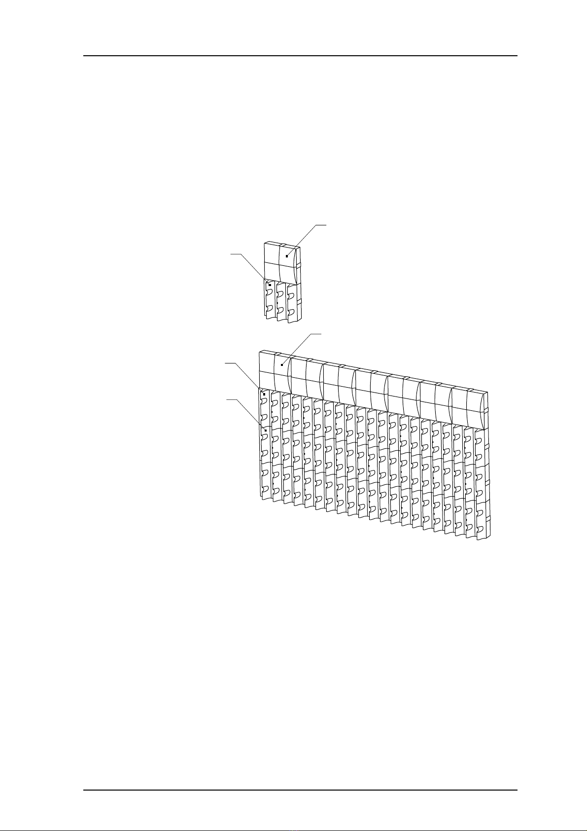
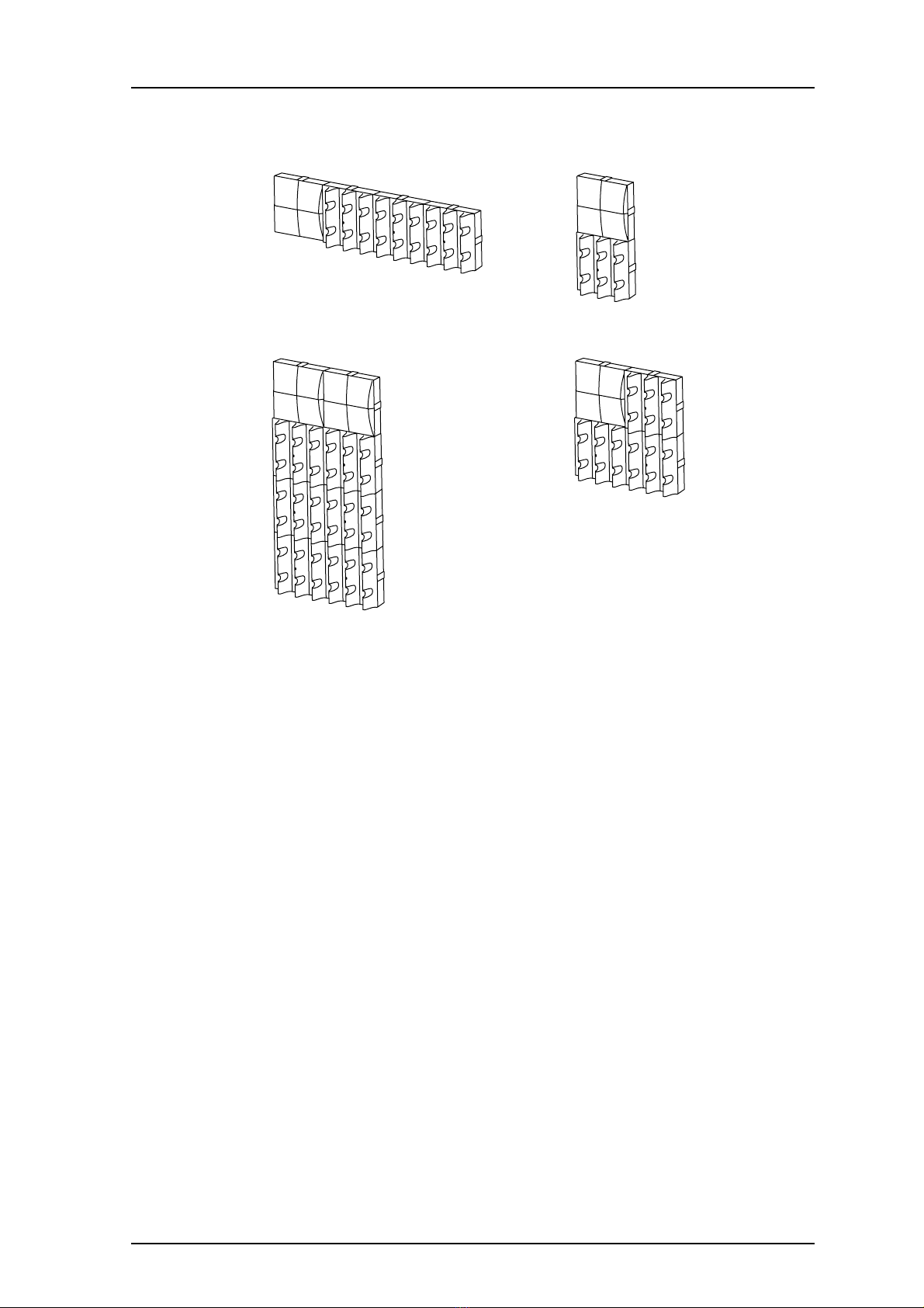
• Every installation must at least consist of one Power Supply CR24 and one Charging
Rack Master PCR-M.
If the ambient temperature is 25 °C or lower the Power Supply CR24 can supply up to
three Charging Racks (Master PCR-M and Extension PCR-E).
If the ambient temperature is higher than 25 °C the Power Supply CR24 can supply up
to two Charging Racks (Master PCR-M and Extension PCR-E).
One Master PCR-M can support up to 20 Extensions PCR-E.
• Suomi: Laite on liitettävä suojamaadoituskoskettimilla varustettuun pistorasiaan.
• Norge: Apparatet må tillkoples jordet stikkontakt.
• Sverige: Apparaten skall anslutas till jordat uttag.
Information to user
This device complies with Part 15 of the FCC Rules. Operation is subject to the following
two conditions:
(1) this device may not cause harmful interference, and
(2) this device must accept any interference received, including interference that may
cause undesired operation.
Modifications
Changes or modifications to the equipment not expressly approved by the party
responsible for compliance could void the user’s authority to operate the equipment.

TD 92356GB
2007-03-16/ Ver. C
Installation Guide
PCR Charging Rack
3
3 Installation
• The units should be placed in a dry environment with a temperature range of
0 to +40º C.
• Avoid mounting the Charging Rack where the coverage is not sufficient. This can
reduce the messaging capacity.
• The PCR Charging Rack module must be mounted according to the label. See figure 6
on page 7.
• The units should be mounted on concrete or plaster walls only.
Delivery includes:
One Inlet accessory kit including;
• Cable supports and screws
• Rectangular assembly covers
• Clips (only used for Power Supply module)
A modular cable is included in the delivery of Extension PCR-E for connection to or from
another Extension PCR-E or Master PCR-M.
Required tools and material:
• Three-wired cable for the mains power with diameter 4-8.5 mm. Make sure that the
used cable is grounded and approved for the current and voltage in question.
• Screwdrivers
• Cutting pliers
• Multimeter
• Screws and wall plugs for wall mounting. Make sure the screws and wall plugs are
correct for the type of wall used. See example below.
Wall material Wall plug Screw diameter
Single plasterboard Thorsman TP1 3.5-5 mm
Double plasterboard Thorsman TP2 3.5-5 mm
Concrete Thorsman TP2 3.5-5 mm

TD 92356GB
2007-03-16/ Ver. C
Installation Guide
PCR Charging Rack
4
3.1 Charging Rack Master PCR-M and Extension PCR-E
Every installation must at least consist of one Power Supply CR24 and one Charging Rack
Master PCR-M. If the ambient temperature is 25 degrees C or lower the Power Supply
CR24 can supply up to three Charging Racks (Master PCR-M and Extension PCR-E). If the
ambient temperature is higher than 25 degrees C the Power Supply CR24 can supply up
to two Charging Racks (Master PCR-M and Extension PCR-E).One Master PCR-M can
support up to 20 Extensions PCR-E.
The Charging Racks are connected (see 6 Connection of Charging Rack Master PCR-M and
Extension PCR-E on page 19) with the modular cable (delivered with the Extension PCR-E).
Figure2.
022
Master PCR-M
Master PCR-M
Extension
PCR-E x 20
Power Supply CR24
Power Supply CR24 x 7
Figure 2. Example of minimum and maximum (if the ambient temperature is
25 degrees C or lower) configuration with one Master PCR-M.

TD 92356GB
2007-03-16/ Ver. C
Installation Guide
PCR Charging Rack
5
3.2 Examples on how to Assemble the Modules
Figure3.
003
Figure 3. Four different examples on how to assemble the PCR Charging Rack.
The Power Supply module can also be placed apart from the Charging Rack modules.
Tip: When you are planning the location of the modules, start to mount them in a height
that makes it easy to reach the portables.

TD 92356GB
2007-03-16/ Ver. C
Installation Guide
PCR Charging Rack
6
3.3 Mounting the Power Supply Module
IMPORTANT: The Power Supply module must be mounted horizontally and with the clips
down.
Figure4.
002
Figure 4. The Power Supply module must be mounted horizontally.
3.4 Mounting the Charging Rack Module
Figure5.
UP
UP
PCR
OTHERS
UP
UP
PCR
OTHERS
023
Figure 5. The Charging Rack modules must be mounted with the arrow marked "UP
PCR" upwards.

TD 92356GB
2007-03-16/ Ver. C
Installation Guide
PCR Charging Rack
7
3.5 Mounting Dimensions
Figure6.
65
65
130
130
127.5
127.5
27
92 184
004
UP
UP
PCR
OTHERS
UP
UP
PCR
OTHERS
Figure 6. Mounting dimensions in mm.
For wall fitting, preparation can be done in two ways:
• Measure and mark out the drill holes by using the dimensions in figure 6. Drill and
fasten the modules on the wall with three screws.
or
• Remove the covers, see 3.6 Removing Covers on page 8 and mount together some of
the modules, see 3.6.3 Mounting Modules Together on page 10. Hold the mounted
modules up against the wall and mark the location of the drill holes. Drill and fasten
the modules on the wall with three screws.
Note: The placing of the holes in the Power Supply module differ from the holes in the
Charging Rack module.

TD 92356GB
2007-03-16/ Ver. C
Installation Guide
PCR Charging Rack
8
3.6 Removing Covers
3.6.1 Power Supply Module
Figure7.
two slots per
module
2
1
005
Figure 7. Removing the cover from the Power Supply module.
1 Put a screwdriver onto the slots and slightly bend the cover upwards (1).
2 Lift up the cover in the direction of the arrow (2).

TD 92356GB
2007-03-16/ Ver. C
Installation Guide
PCR Charging Rack
9
3.6.2 Charging Rack Module
Figure8.
006
1
2
1
Figure 8. Removing the cover from the Charging Rack module
1 Unscrew the two screws (1).
2 Lift up the front in the direction of the arrow (2).

TD 92356GB
2007-03-16/ Ver. C
Installation Guide
PCR Charging Rack
10
3.6.3 Mounting Modules Together
Figure9.
007
1
1
Figure 9. Mounting modules together.
1 Fasten the two adjacent modules together with two rectangular assembly covers,
(which are provided in the parts bag). Place two covers in the adjoining slot (1).
Note: The Charging Rack modules must be mounted with the marking text, “UP
PCR”, upwards, see figure 5 on page 6. The Power Supply module must be
mounted horizontally and with the clips down, see figure 4 on page 6.
2 Fasten each module on the wall with three screws, see figure 6 on page 7.

TD 92356GB
2007-03-16/ Ver. C
Installation Guide
PCR Charging Rack
11
3 Mount two clips (which are provided in the parts bag) in the Power Supply module.
(2).
Figure10.
008
2
2
Figure 10. Mounting of clips. Only in the Power Supply module.
4 Mount rectangular covers (which are provided in the parts bag) at the openings
where there are no adjacent modules (3), see figure 11 below.
5 Fasten the cover’s angled hooks on the holders (4).
6 Snap on the Power Supply module cover (5).
7 Fasten the screws in the Charging Rack module cover.
Figure11.
4
5
3
3
009
Figure 11. Power Supply module, mounting of rectangular covers and replacing the
covers.

TD 92356GB
2007-03-16/ Ver. C
Installation Guide
PCR Charging Rack
12
4 Connection of Power Supply CR24
Figure12.
010
LN
+-
-V-V +V+V
OUTPUT
V
ADJ
INFG
Figure 12. Power Supply module.
IMPORTANT: The Power Supply module connects to 100 - 250 V AC. When working
with the units the mains power supply cable must always be disconnected.
For safety the covers must always be mounted after an installation. The
voltage safety cover has to be mounted on top of the voltage connector in
the Power Supply module to prevent hazardous situations, like electric
shock, see figure 16 on page 14.
4.1 Connection of Mains Power Supply Cable (AC)
1 Unscrew the voltage safety cover.
Figure13.
LN
+-
-V-V +V+V
OUTPUT
V
ADJ
INFG
011
Figure 13. Removing the voltage safety cover.

TD 92356GB
2007-03-16/ Ver. C
Installation Guide
PCR Charging Rack
13
2 Run the mains power supply cable through the cable support holder (which is
provided in the parts bag).
Figure14.
012
Figure 14. Mains power supply cable with cable support holder.
3 Cut and strip the mains power supply cables.
4 Connect the mains power supply cable onto the indicated positions on the
connector, see figure 15.
Figure15.
LN
+-
-V-V+V+V
OUTPUT
INFG
100 - 250 V AC
013
Figure 15. The mains power supply connection.

TD 92356GB
2007-03-16/ Ver. C
Installation Guide
PCR Charging Rack
14
5 Mount the voltage safety cover on its position (1), fasten it with one screw (2), see
figure 16.
IMPORTANT: To prevent hazardous situations like electric shock, the voltage safety cover
must always be mounted before the power is switched on.
Figure16.
LN
+-
-V-V +V+V
OUTPUT
V
ADJ
INFG
014
1
2
2
Figure 16. Mounting of the voltage safety cover.

TD 92356GB
2007-03-16/ Ver. C
Installation Guide
PCR Charging Rack
15
4.2 Wiring Run
Mains Power Supply Cable (AC)
Note: To avoid cable break, make sure that the cable is not tight around the sharp edge of
the power supply.
1 Secure the mains power supply cable with two screws (1), which are provided in the
parts bag.
2Mount the cable support holder at the opening on the Power Supply module,
closest to where the wall socket is placed (2).
Figure17.
015
2
1
1
Figure 17. Securing the mains power supply cable (1) and mounting of the cable
support holder (2).

TD 92356GB
2007-03-16/ Ver. C
Installation Guide
PCR Charging Rack
16
Supply Voltage Cable (DC)
The +5 V DC supply voltage cable is pre-assembled.
1 If possible run the +5 V DC supply voltage cable around the cable support, to avoid
cable break. See figure 18.
Figure18.
UP
UP
PCR
OTHERS
017
Figure 18. +5 V DC supply voltage cable support.

TD 92356GB
2007-03-16/ Ver. C
Installation Guide
PCR Charging Rack
17
4.3 Connection of Supply Voltage Connector
IMPORTANT: Power Supply CR24 is the only power supply that can be used together
with PCR Charging Rack.
Connect the +5 V DC supply voltage connector to J3.
Figure19.
018
J3
+5 V DC
GND
Figure 19. Position of connector J3.

TD 92356GB
2007-03-16/ Ver. C
Installation Guide
PCR Charging Rack
18
5 Maintenance Information
5.1 Upgrading the Software
Note: Only Mater PCR-M is possible to upgrade.
1 Attach a serial cable (Interface Cable U982 & PCR, Art.No. 660142) between
connector J403 on the Master PCR-M, see figure 20 below, and a PC.
Figure20.
1
J403
024
Figure 20. Attach the arrow marking to pin 1 on J403.
2 Switch to software download mode by setting "Section 1" on SW400 to ON, see
Switch SW400 Configuration on page 22.
3 Perform a reset by pressing the reset button SW300, see 8 Board Description,
Master PCR-M and Extension PCR-E on page 21.
Make sure that the Function Indicator indicates Software Download Mode, see
figure 5 on page 6.
4 Open the software "Ascom Loader", see figure 21below.
Figure 21.
Figure 21. Ascom Loader main view.
5 Check the communication settings by: Settings > Communication:
• Baud rate: 115200 (normally)
• Com port: Check active Com port settings
6 Open the upgrade file by: File > Open. Then select required file to download.
7 Upgrade the Master PCR-M by selecting: Target > Program. The upgrading starts.
The upgrade is completed when "Job succeded!" appears. Press OK to confirm.
Table of contents
Other ASCOM Batteries Charger manuals