CSL BB9300 User manual

- 1 -
SERVICE MANUAL
1. Main Functions:
-Audio Play/Video Recording
-Master /SLAVE GSM 900/1800MHz
-MMS/WAP
-Bluetooth 1.2
2. Main Selling Points
-BT communication
-FM supporting
-GPRS Class 12
-Support MP3, MP4
3. Other Functions
-Slide-Rotating
4. Spec
-SIZE 75X70X15mm
2.4" TFT 26K

- 2 -
INTRODUCTION
The purpose of this document is to help service workshop technicians to service products. This service
TABLE OF CONTENTS
INTRODUCTION………………………………………………………………………………..3
Chapter 1 EXPLODED VIEW AND COMPONENT DISPOSAL………………………….4
EXPLODED DIAGRAM………………………………………………………………………….……...4
DISASSEMBLY AND ASSEMBLY …………………………………………………………….………5
SERVICE TOOLS………………………………………………………………………………...5
DISASSEMBLE…………………………………………………………………………………...7
ASSEMBLY………………………………………………………………………………………..9
Chapter 2 SYSTEM BLOCK DIAGRAM……………………………………………………..11
Chapter 3 INSTRUCTION OF THE UNIT CIRCUIT………………………………………...12
Chapter 4 ACTUALL BOARD…………………………………………………………….….21
SIDE A (MASTER)…………………………………………..……………………………………….….21
SIDE B (SLAVE)……………………………………………………………………………………...….21
Chapter 5 TROUBLESHOOTING……………………………………………………………22
Chapter 6 SOFTWARE INSTRUCTION OF SW UPDATE………………………………..28
SW UPDATE OF MASTER……………………………………………………………..………………32
SW UPDATE OF SLAVE…………………………………………………………………………..……35
Chapter 7 FUNCTION TEST………………………………………………………………….39
Chapter 8 PARAMETER SETTING INSTRUCTION……………………………………….40
Chapter 9 CATCHER INSTRUCTION……………………………………………………….42

- 3 -
manual must be used only by authorized service suppliers. The content of it is confidential. Please note that
provides other guidance documents for service suppliers. Follow these regularly and comply with the given
instructions. While every effort has been made to ensure the accuracy of this document, some errors may
exist. Please keep in mind also that this documentation is continuously being updated and modified, so
always watch out for the newest version.
CAUTIONS
Please refer to the phone’s user’s guide for instructions relating to operation, care, and maintenance,
which include important safety information.
1. Servicing and alignment must be undertaken by qualified personnel only.
2. Ensure all work is carried out at an anti-static workstation and that an anti-static wrist strap is worn.
3. Use only approved components as specified in the parts list.
4. Ensure all components, modules, screws, and insulators are correctly re-fitted after servicing and
alignment
5. Ensure all cables and wires are repositioned correctly
Electrostatic discharge can easily damage the sensitive components of electronic products. Therefore,
every service supplier must observe the precautions which mentioned above.
GENERAL REPAIR INFORMATION
1. Make sure your testing equipment is functioning properly before beginning repair work.
2. Before starting repairs you must observe ESD precautions such as being in your ESD
protected area and connecting your wristband.
3. Use gloves to avoid corrosion and fingerprints.
4. Cover windows and displays with a protective film to avoid dust and scratches.
5. Use a lint-free cloth to clean the LCD.
6. When cleaning the pads use a soft cloth\ESD brush and isopropanol. Do not use a glass
fiber pencil: this scratches the surface and will corrosion.
7. Non-faulty mechanical parts(except shielding lids and bent parts or soldered components).
May be reused if they are not soldered.
8. When removing the shielding lids make sure to replace them with new ones, otherwise the
high-frequency leakage can affect the device.
9. Always use the original spare parts.
10. Check the soldering joints of the parts concerned with regard to the fault symptom. And
resolder them if necessary.
11. Remove excess soldering flux after repair.
12. Observe the torque requirements when assembling the unit.
13. please aware that some malfunctions may be software related and solved by an update

- 4 -
Chapter 1
EXPLODED VIEW AND COMPONENT DISPOSAL
EXPLODED DIAGRAM
- 5 -
DISASSEMBLY AND ASSEMBLY
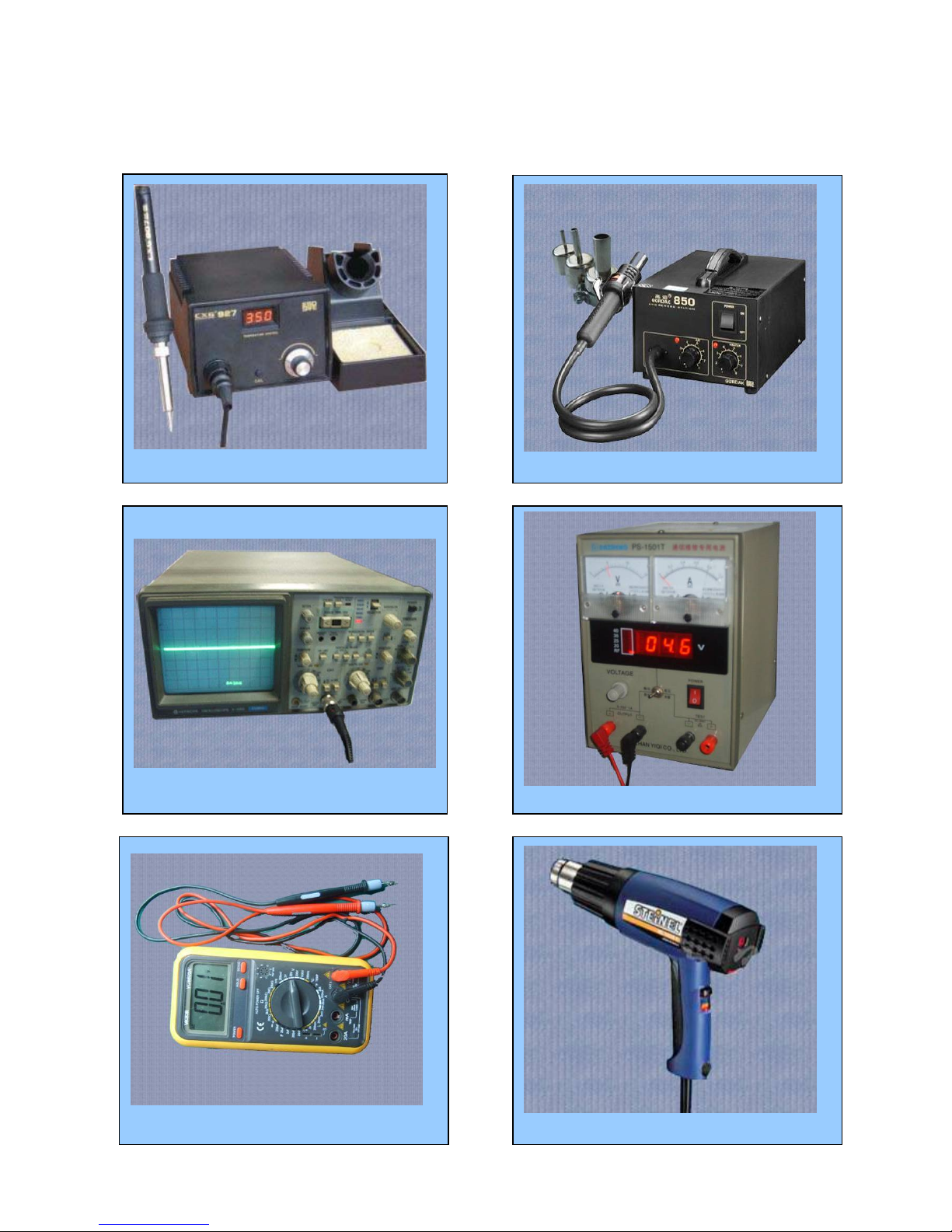
SERVICE TOOLS
Voltage regulator
Multimeter
Iron
850 heater
Constant temperature heater
Oscillograph
- 6 -
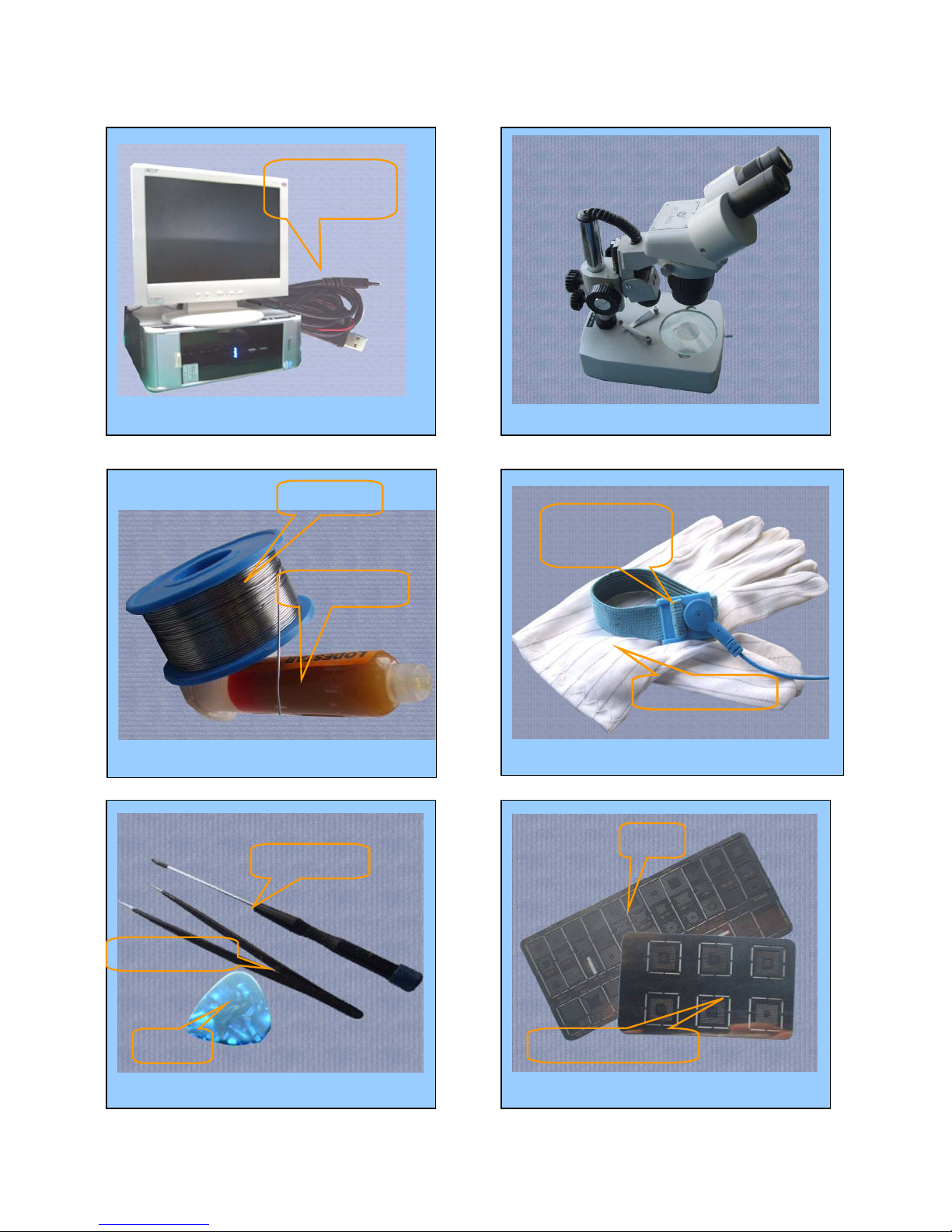
Computer and software download cable
Wrist grounding strap, Antistatic gloves
Wrist
grounding strap
Antistatic gloves
Software
download cable
Microscope
Solder wire, soldering paste
Metal tweezers, Screw driver, SRT-6 Plates
Metal tweezers
SRT-6
Screw driver
MTK series CPU plate
Plate
soldering paste
Solder wire
- 7 -
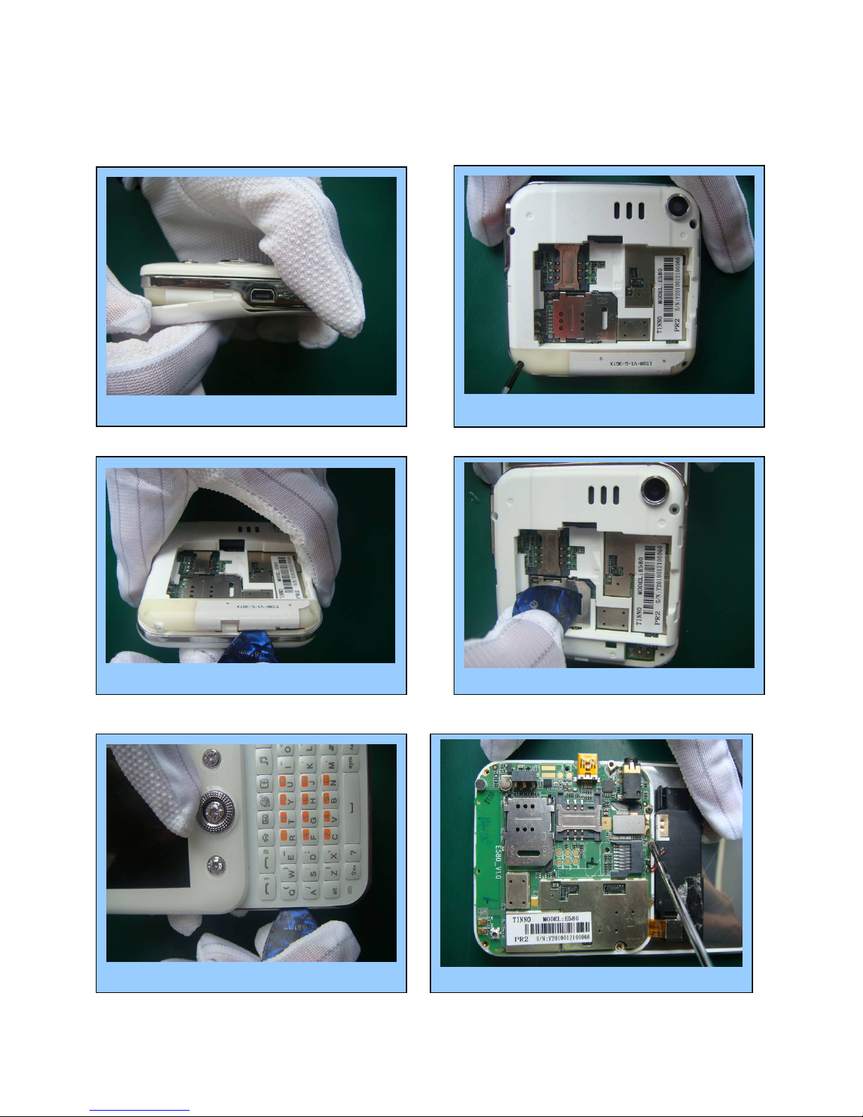
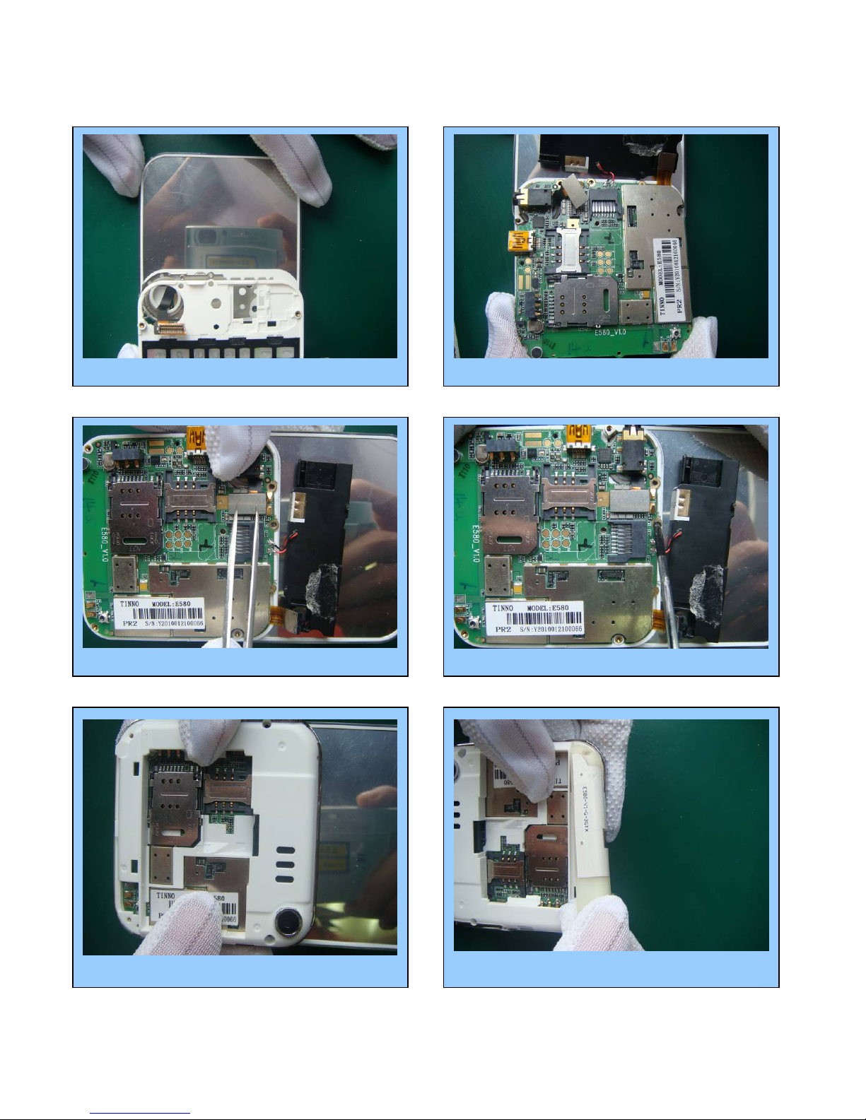
DISASSEMBLY
Take out the battery cover. Remove 4 screws with screw driver.
Prize up the antenna by pick Prize up SIM buckle
Prize up D cover with pick Remove 2 screws with tweezer

- 8 -
⑺Take down FPC connector with pick ⑻Take off PCBA by tweezer
⑼Take out C cover with hands
⑽Take off 4 screws by tweezer
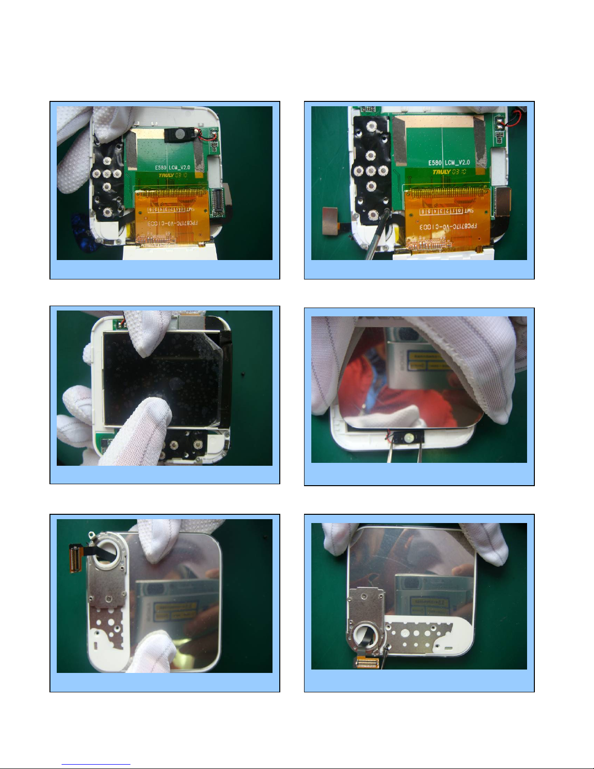
⑾Prize up B cover with tweezer ⑿Stick LCD film

- 9 -
Finish
⒀stick lens protection film ⒁Take off receiver by tweezer
⒂Separate LCD with pick
⒄separate LCD PCBA with tweezer
⒃Take off the screw with tweezer
⒅Take off FPC
- 10 -
ASSEMBLY
⑴Place LCD PCBA in A cover ⑵Lock the screw
⑹Lock the screws with tweezer⑸install B cover
⑷Install receiver with tweezer
⑶Install LCD
- 11 -
⑺Install cover C
⑿Install the antenna⑾Connect FPC with PCBA board
⑽Lock 3 screws with tweezer
⑻Place main PCBA in C cover
⑼Tighten the FPC connector

- 12 -
Finish
⒀Lock 4 screws ⒁Button the battery cover

- 13 -
Chapter 2
SYSTEM BLOCK DIAGRAM
CPU (MT6235)

- 14 -
Chapter 3
INSTRUCTION OF THE UNIT CIRCUIT
1. Instruction of the important ICs :
CPU is MT6235 which is the kernel IC of whole main circuit. It also integrates subsystems of channel coder and decoder, cross and
de-cross, encryption and decryption. It takes charge of process of voice and every parts of mobile, such as charge, liberation, LED
etc. And it includes WATCHDOG to improve system stability.
MT6235 is a new generation high-end chip made by MEDIATEK, with a QFN 11.5mm*11.5mm, up to 261pins, 0.47pitch. MT6235
baseband chip has GSM/GPRS capability, also integrates audio and video function. MT6253 provides not only high-quality GPRS
Class 12 MODEM, high-rate data transmission service, but also multi-media applications, like 0.3M pixels camera, mp3, mp4 etc
32k clock si
g
nal
BT control
signal
Keypad
signal
Flash signal
MT6235 CPU

- 15 -
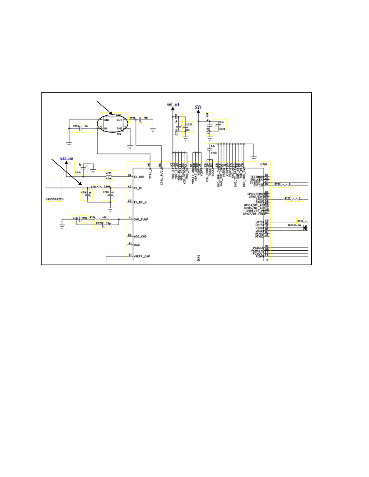
FM circuit
U204 is FM receiving module. FM_ANT is used to receive the radio signal from the antenna, FM_VCC is the
2.8Vpower supply, FM32KHz is the reference clock, GPIO26 and GPIO31 is control signal from the baseband CPU.
FM ANT
FM output
- 16 -
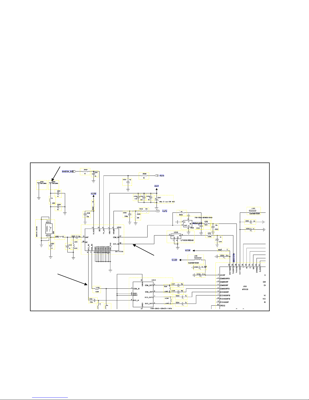
RF circuit
RF part generally means the analog RF and IF process system ,including Antenna system、TX path、RX path、Analog
modem and Frequency Synthesizer .
RF Circuit deals with the RX and TX of wireless signal, with responsibility for the bidirectional transmission of speech and data
between the MS and BS through the air interface. In detail RX part accomplishes the AGC amplifying, mix and demodulation
of RF weak signal received from BS, The final signal output from RX part is the analog baseband I/Q signal. The final RX I/Q
will be sent to Baseband Circuit for later disposal. On the other hand TX part deals with the signal modulation, up-conversion
mix and power amplifying of analog I/Q signal received from baseband, generating burst which meets the GSM specification.
And then the bursts are transmitted to Base station through the antenna. The signal interface between
RF Circuit and Baseband is analog baseband I/Q signal. The performance of RF Circuit can directly affects the signal
transmission quality of the mobile phone.
RF PA adopts RF7161 chip, RF7161 is a high-power dual-mode amplifier module with internal power control.
RPF88150B is used in the stage when GSM / GPRS dual-mode mobile phones amplify transmission array, the working
frequency is from 824MHz to 915MHz and 1710MHz to 1910MHz. There is a input pin to realize the selection of
frequency band. 6mm * 6mm chip package.
Rx path
Tx path
ANT
- 17 -
BT circuit
Bluetooth IC processor is MT6612BN/A..
MT6612 is 5mm x 5mm 40-lead (0.5mm pitch) QFN, a high-integrated Bluetooth IC, including rich function and strong
disposal capability, and high performance transceiver.
BT ANT
32MHz clock
- 18 -
Chapter4
ACTUALL BOARD
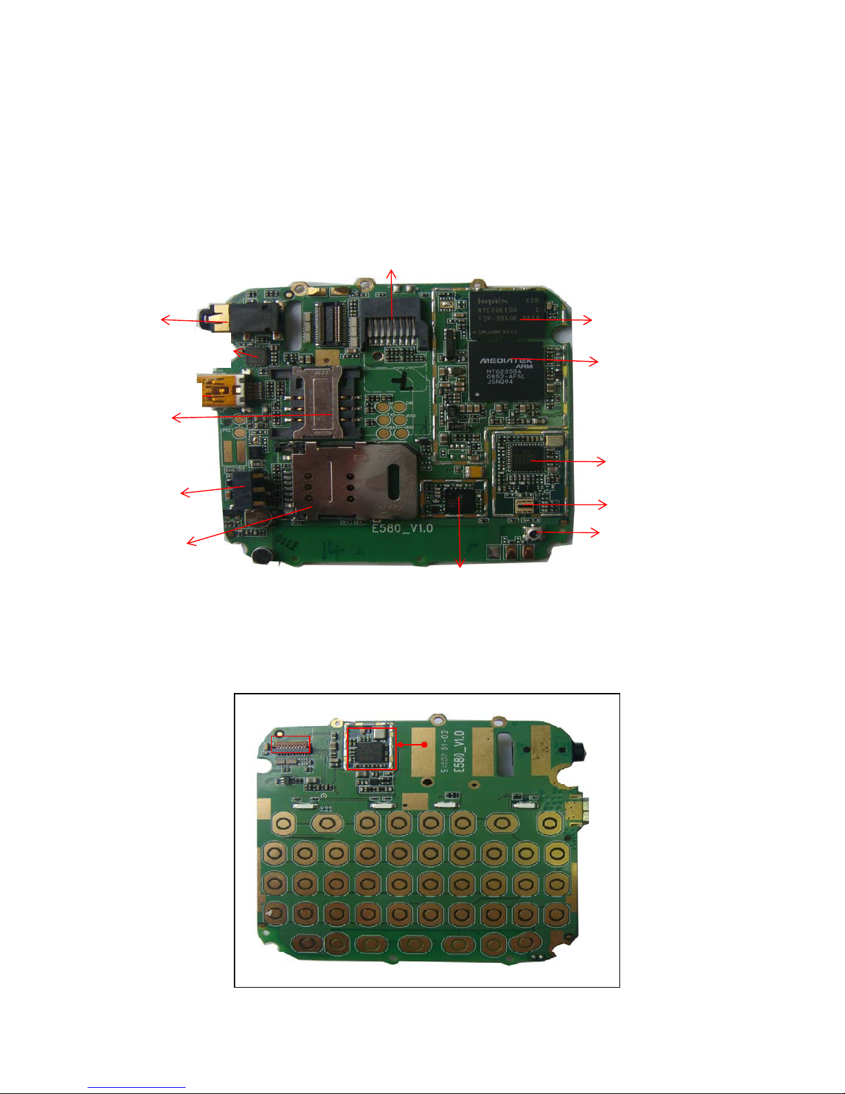
SIDE A
SIDE B
U101 CPU
CPU MTK
U301 Flash
J201Battery
connecto
r
n
J302 I/O connector
J703 SIM slot
J702 SIM slot J501 RF connector
J202 T-flash connector
U501 RF IC
U702 FM IC
U503 antenna switch module
U502 RF PA IC
J303 Earphone
t
U801 BT IC
Camera
connector

- 19 -
Chapter5
TROUBLE SHOOTING
NO
Test flowchart of SIM card
Replace SIM
card
Baseband IC U101may
have fault
Could not read
SIM card
Clean or replace
SIM socket
If points of
SIM are OK
NO NO
NO
YES
YES
YES
YES OK
End
If SIM card is
invalidation
Connect to steady-voltage
power supply to see if
current is OK
Power may be damaged. Test if
voltage of J403 pin4/5 at exactly
power on is 3V. If pin 1/2/3 has
switch of pulse voltage
Replace U101
NO

- 20 -
Test flowchart of can not power on (for master)
Replace
battery
May be MT6235 is fault
Could not power
on
Re-solder or replace
J103 of battery
If battery point
of J103 is OK
NO
NO
NO
NO
YES
YES
YES OK
End
Connect to power
supply, if it can be
p
ower on
If current is 30-40Mx Update software to
the latest version
Replace/resolder U101
NO
Table of contents
Other CSL Cell Phone manuals


