CSL G16 User manual
- 1 -
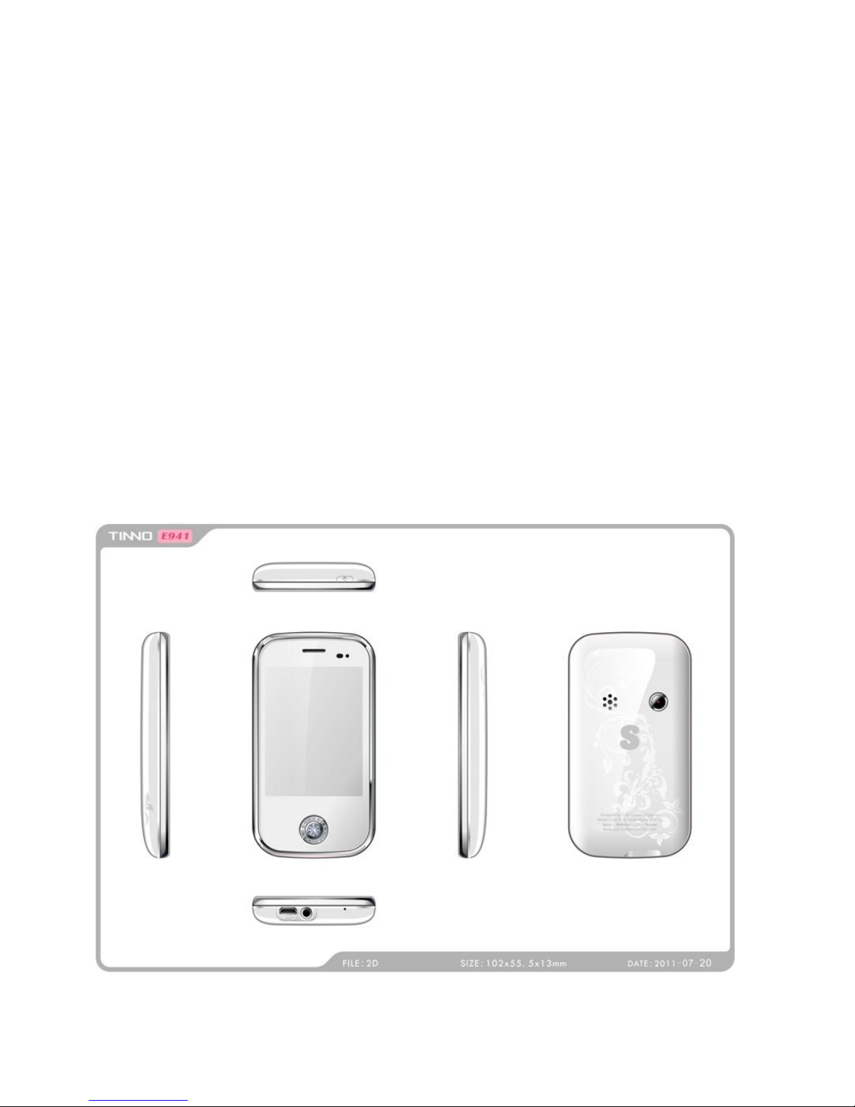
G16(EM941) SERVICE MANUAL
GSM/GPRS 900/1800MHz
Support EDGE, only downloading.
WAP/MMS
GPRS Class 12
player
MP3 player
music library
SRS
Voice Recorder
FM Radio
Micro USB 2.0
JAVA
Main WIFI
Blue tooth
MSN,Yahoo messenger,Youtube, Google talk,
Facebook,Twitter,Mini Opera,Google search
3.5mm Audio Jack,Yamaha amplifie

- 2 -
INTRODUCTION
The purpose of this document is to help service workshop technicians to service products. This service
manual must be used only by authorized service suppliers. The content of it is confidential. Please note that
provides other guidance documents for service suppliers. Follow these regularly and comply with the given
instructions. while every effort has been made to ensure the accuracy of this document, some errors may
exist. please keep in mind also that this documentation is continuously being updated and modified, so
always watch out for the newest version.
CAUTIONS
Please refer to the phone’s user’s guide for instructions relating to operation, care, and maintenance,
which include important safety information.
1. Servicing and alignment must be undertaken by qualified personnel only.
2. Ensure all work is carried out at an anti-static workstation and that an anti-static wrist strap is worn.
3. Use only approved components as specified in the parts list.
4. Ensure all components, modules, screws, and insulators are correctly re-fitted after servicing and
alignment
5. Ensure all cables and wires are repositioned correctly
Electrostatic discharge can easily damage the sensitive components of electronic products. Therefore,
every service supplier must observe the precautions which mentioned above.
GENERAL REPAIR INFORMATION
1. Make sure your testing equipment is functioning properly before beginning repair work.
2. before starting repairs you must observe ESD precautions such as being in your ESD
protected area and connecting your wristband.
3. use gloves to avoid corrosion and fingerprints.
4. cover windows and displays with a protective film to avoid dust and scratches.
5. use a lint-free cloth to clean the LCD.
6. when cleaning the pads use a soft cloth\ESD brush and isopropanol. Do not use a glass
fiber pencil: this scratches the surface and will corrosion.
7. non-faulty mechanical parts(except shielding lids and bent parts or soldered components).
May be reused if they are not soldered.
8. when removing the shielding lids make sure to replace them with new ones, otherwise the
high-frequency leakage can affect the device.
9. always use the original spare parts.
10. check the soldering joints of the parts concerned with regard to the fault symptom. And
resolder them if necessary.
11. remove excess soldering flux after repair.
12. observe the torque requirements when assembling the unit.
13. please aware that some malfunctions may be software related and solved by an update
- 3 -
DISASSEMBLY AND ASSEMBLY
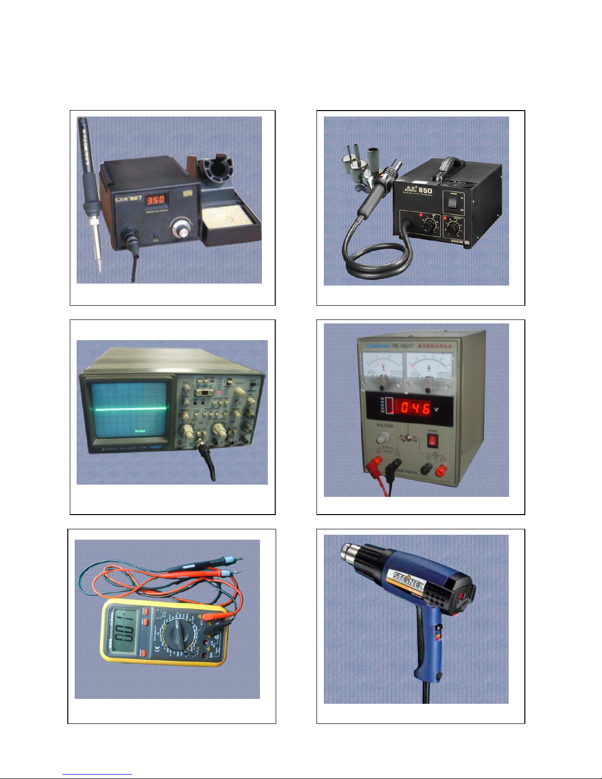
SERVICE TOOLS
Voltage regulator
Multimeter
Iron
850 heater
Constant temperature heater
Oscillograph

- 4 -
Wrist grounding strap, Antistatic gloves
Wrist
grounding strap
Antistatic gloves
Software
download cable
Microscope
Solder wire, soldering paste
Metal tweezers, Screw driver, SRT-6 Plates
Metal tweezers
SRT-6
Screw driver
MTK series CPU plate
Plate
soldering paste
Solder wire
- 5 -
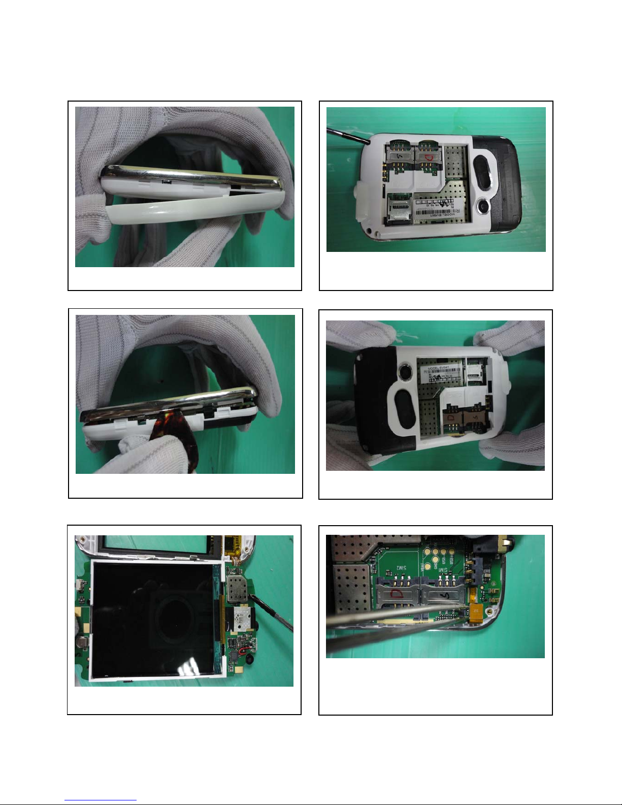
DISASSEMBLY
Pull out battery cover.
Take out the screws.
Take off the back cover.
Separate the FPC connector
Take off the screw
Prize up the middle housing.

- 6 -
Paste the film on lens and LCD
Take PCBA out of A cover
Take off the main key

- 7 -
ASSEMBLY
Put the PCBA into A cover
Close the FPC connector
Put the cover on the PCBA Install the screw
Close back cover and front cover together.
Install power on key

- 8 -
-FINISH-
Lock the screws
Assemble battery cover

- 9 -
Chapter 2
SYSTEM BLOCK DIAGRAM
- 10 -
Chapter4
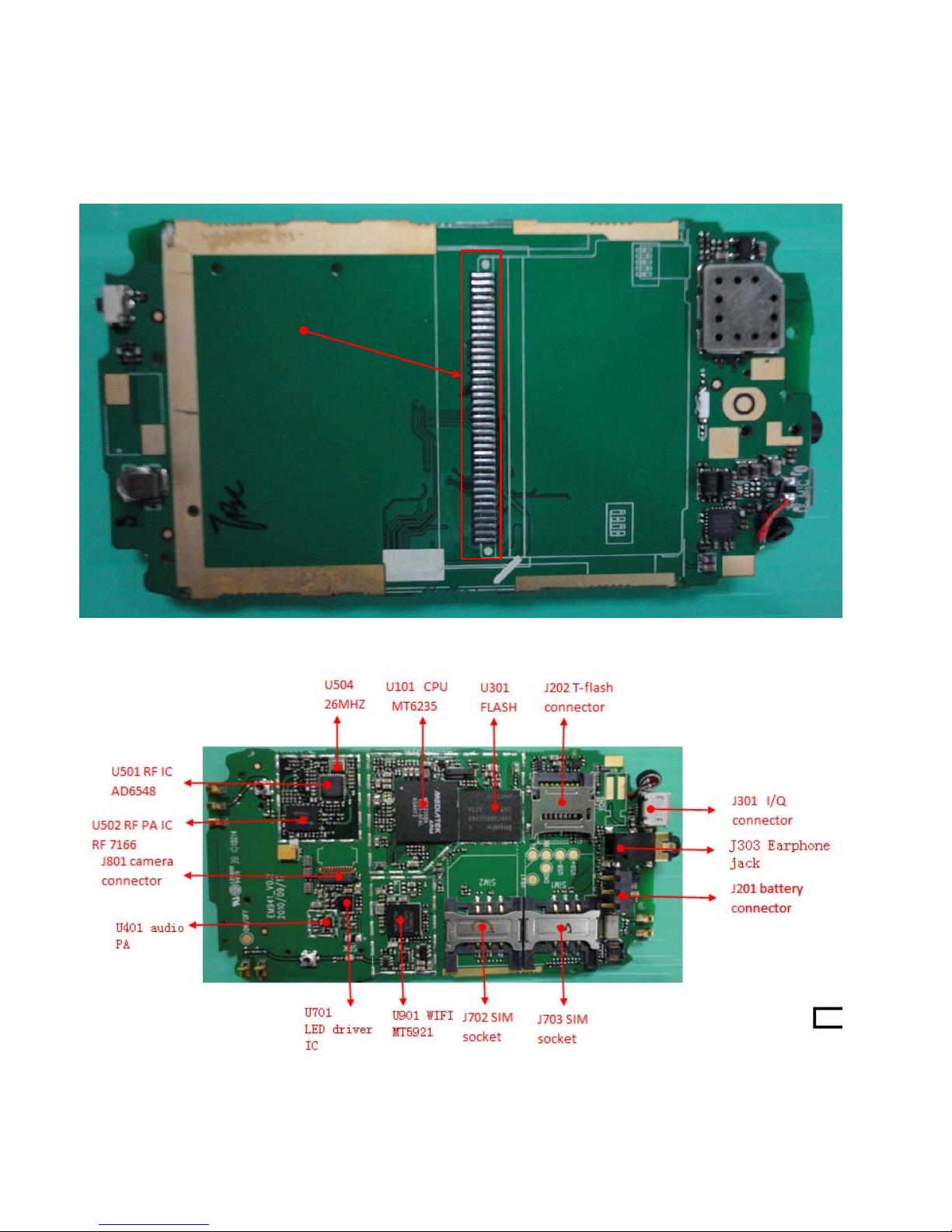
ACTUALL BOARD
PCBA layout drawing A side:
J701 LCD connector
- 11 -
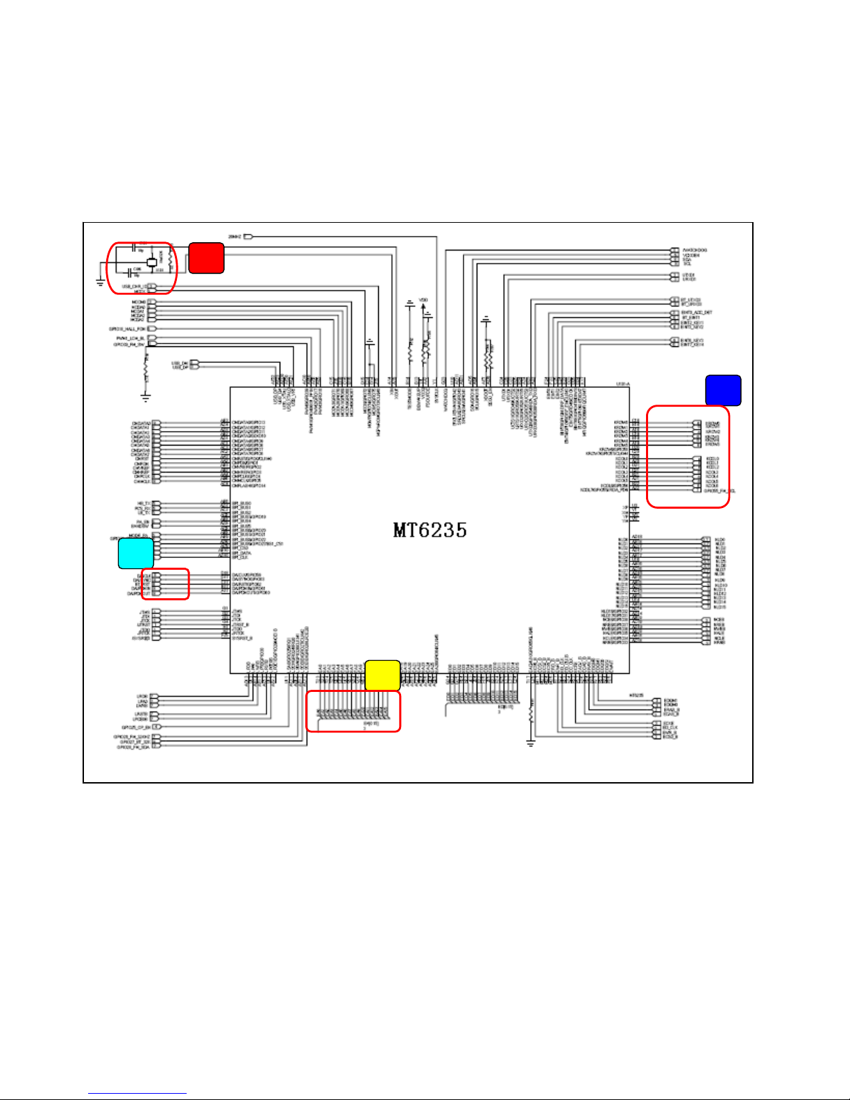
Electronic schemes
Main CPU
③
①
②
④

- 12 -
Keypad input
①
- 13 -
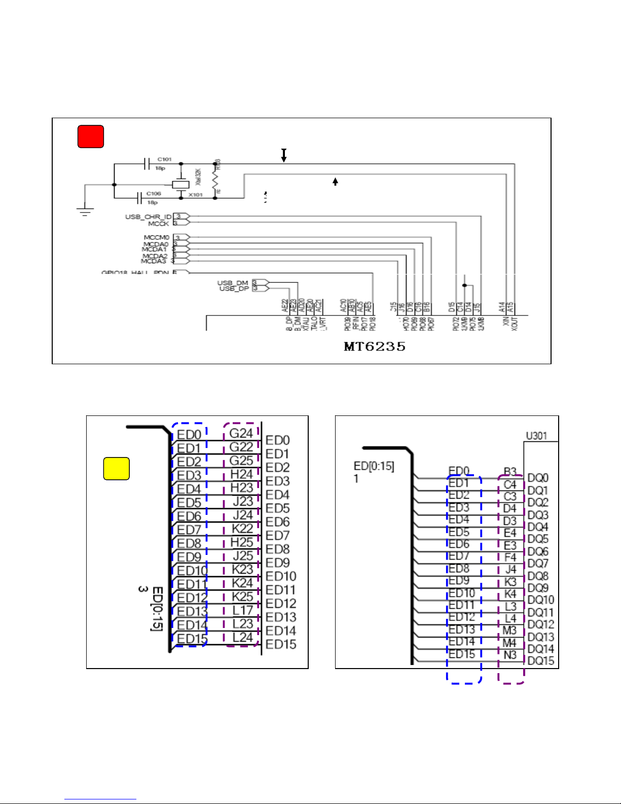
Oclock Electronic schemes
②
Cable and flash connect sheet
③
Oclock out put

- 14 -
BT control
④
⑤
SIM card data out put
7.2 MT6235 CPU power output

- 15 -
item voitage current
Vcore 1.2v 200ma
Vio 2.8v 100ma
Vadd 2.8v 150ma
Vtcxo 2.8v 20ma
Vrtc 1.2v 200ma
Vmem 2.8v 150ma
Vsim 2.8v 20ma
Vcs 2.8v 200ma
vcs 1.8v 150ma
CPU voitage and current sheet
由主机 CPU送
来的 SIM 卡控
制信号.控制着
主机 SIM 卡的
工作.
7.3 battery connector

- 16 -
BT MODEL
- 17 -
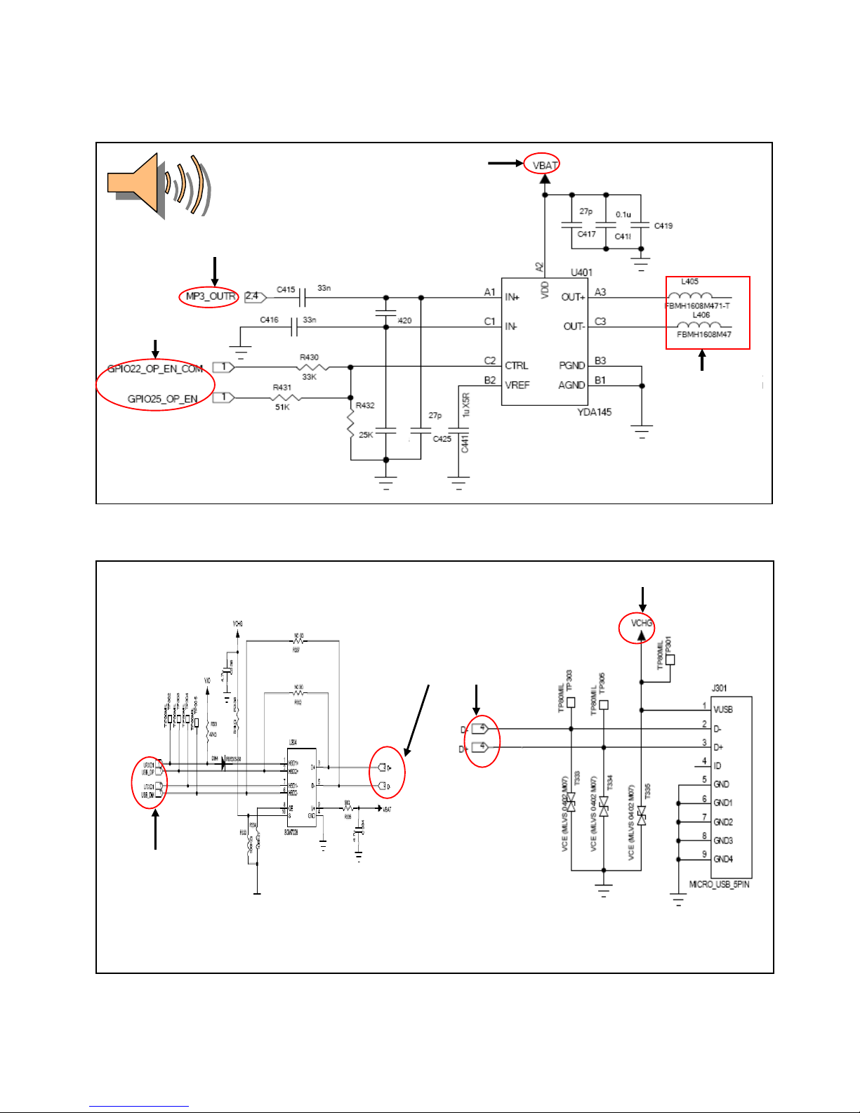
Audio PA U201
I/O connector (5PIN)
数据传输端
充电输入端
数据输入端
- 18 -
PA IC
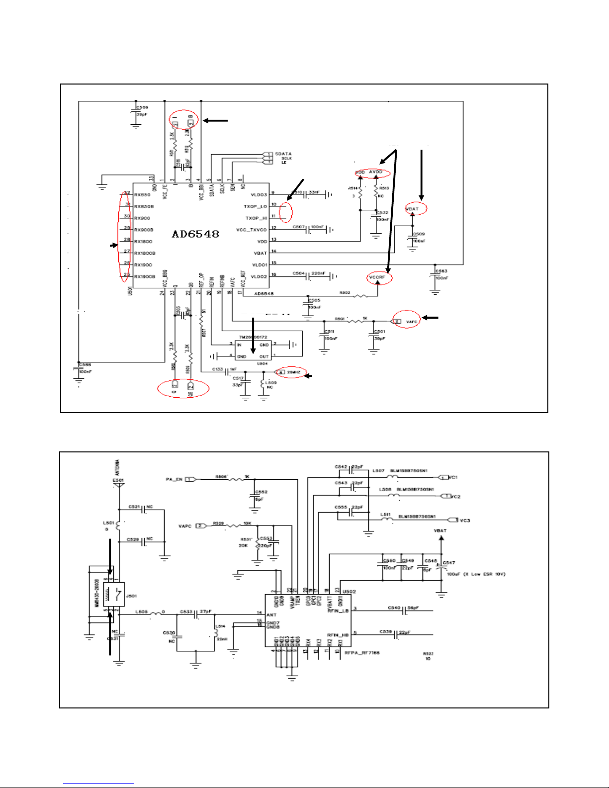
RF—AD6548
RF7166

- 19 -
FM
SIM card
SIM 1 SIM 1power
su
pp
lie
r
SIM 1 data
SIM 2 power
su
pp
lier
SIM 2

- 20 -
8.0 WIFI
2.Control loop
This manual suits for next models
2
Table of contents
Other CSL Cell Phone manuals


