CST/BERGER iLMXT User manual

de Originalbetriebsanleitung
en Original instructions
fr Notice originale
es Manual original
pt Manual original
it Istruzioni originali
nl Oorspronkelijke
gebruiksaanwijzing
da Original brugsanvisning
sv Bruksanvisning i original
no Original driftsinstruks
fi Alkuperäiset ohjeet
el Πρωττυπο οδηγιών χρήσης
tr Orijinal işletme talimatı
pl Instrukcja oryginalna
cs Původní návod k používání
sk Pôvodný návod na použitie
hu Eredeti használati utasítás
ru Оригинальное руководство по
эксплуатации
uk Оригінальна інструкція з
експлуатації
ro Instrucţiuni originale
bg Оригинална инструкция
sr Originalno
uputstvo za rad
sl Izvirna navodila
hr Originalne upute
za rad
et Algupärane kasutusjuhend
lv Instrukcijas oriinālvalodā
lt Originali instrukcija
Mini Laser Cross Level
iLMXT, iLMXTE, iLMXTG
1
23
4
OBJ_BUCH-931-004.book Page 1 Friday, August 14, 2009 12:12 PM

22 610 A15 118 • 14.8.09
Deutsch . . . . . . . . . . . . . . . . . . . . . . . . . . . . Seite 7
English . . . . . . . . . . . . . . . . . . . . . . . . . . . . . Page 13
Français . . . . . . . . . . . . . . . . . . . . . . . . . . . . Page 19
Español . . . . . . . . . . . . . . . . . . . . . . . . . . . Página 25
Português . . . . . . . . . . . . . . . . . . . . . . . . . Página 31
Italiano . . . . . . . . . . . . . . . . . . . . . . . . . . . . Pagina 37
Nederlands . . . . . . . . . . . . . . . . . . . . . . . . Pagina 43
Dansk . . . . . . . . . . . . . . . . . . . . . . . . . . . . . . . Side 48
Svenska . . . . . . . . . . . . . . . . . . . . . . . . . . . . . Sida 53
Norsk . . . . . . . . . . . . . . . . . . . . . . . . . . . . . . . Side 58
Suomi. . . . . . . . . . . . . . . . . . . . . . . . . . . . . . . Sivu 63
Ελληνικά. . . . . . . . . . . . . . . . . . . . . . . Σελίδα 68
Türkçe . . . . . . . . . . . . . . . . . . . . . . . . . .Sayfa 75
Polski. . . . . . . . . . . . . . . . . . . . . . . . . . Strona 80
Česky. . . . . . . . . . . . . . . . . . . . . . . . . . Strana 86
Slovensky . . . . . . . . . . . . . . . . . . . . . . Strana 91
Magyar . . . . . . . . . . . . . . . . . . . . . . . . . Oldal 97
Русский. . . . . . . . . . . . . . . . . . . . . Страница 103
Українська . . . . . . . . . . . . . . . . . . . Сторінка 110
Română. . . . . . . . . . . . . . . . . . . . . . . . Pagina 117
Български. . . . . . . . . . . . . . . . . . . Страница 123
Srpski . . . . . . . . . . . . . . . . . . . . . . . . . Strana 130
Slovensko . . . . . . . . . . . . . . . . . . . . . . . Stran 136
Hrvatski . . . . . . . . . . . . . . . . . . . . . . .Stranica 142
Eesti . . . . . . . . . . . . . . . . . . . . . . . . . Lehekülg 147
Latviešu . . . . . . . . . . . . . . . . . . . . . . Lappuse 152
Lietuviškai . . . . . . . . . . . . . . . . . . . . .Puslapis 158
OBJ_BUCH-931-004.book Page 2 Friday, August 14, 2009 12:12 PM

| 32 610 A15 118 • 14.8.09
1
23
4
1
23
4
1
5
23
4
2
34
5
iLMXT
OBJ_BUCH-931-004.book Page 3 Friday, August 14, 2009 12:12 PM

4| 2 610 A15 118 • 14.8.09
1
1
23
4
1
23
4
B
A
6
89
10
11
13
12
7
OBJ_BUCH-931-004.book Page 4 Friday, August 14, 2009 12:12 PM

| 52 610 A15 118 • 14.8.09
C2
C1
4,6 m
ca. 5 m
2,5 m
2,5 m
0,3 m
A2
1
W2
b
1
a
1
b
2
b
2
a
2
a
2
W1
W2 W1
5 m
0,3 m
0,3 m
OBJ_BUCH-931-004.book Page 5 Friday, August 14, 2009 12:12 PM

6| 2 610 A15 118 • 14.8.09
14
17
16
16
15
17
15
D
OBJ_BUCH-931-004.book Page 6 Friday, August 14, 2009 12:12 PM

Deutsch | 72 610 A15 118 • 14.8.09
de
Sicherheitshinweise
Sicherheitshinweise für
Messwerkzeuge
Sämtliche Anweisungen sind zu
lesen und zu beachten, um mit dem
Messwerkzeug gefahrlos und
sicher zu arbeiten. Machen Sie
Warnschilder am Messwerkzeug
niemals unkenntlich. BEWAHREN
SIE DIESE ANWEISUNGEN GUT
AUF.
fVorsicht – wenn andere als die hier angege-
benen Bedienungs- oder Justiereinrichtun-
gen benutzt oder andere Verfahrensweisen
ausgeführt werden, kann dies zu gefährli-
cher Strahlungsexposition führen.
fDas Messwerkzeug wird mit einem Warn-
schild in englischer Sprache ausgeliefert (in
der Darstellung des Messwerkzeugs auf der
Grafikseite mit Nummer 7 gekennzeichnet).
fÜberkleben Sie den englischen Text des
Warnschildes vor der ersten Inbetriebnahme
mit dem mitgelieferten Aufkleber in Ihrer
Landessprache.
Richten Sie den Laserstrahl nicht
auf Personen oder Tiere und bli-
cken Sie nicht selbst in den Laser-
strahl. Dieses Messwerkzeug erzeugt
Laserstrahlung der Laserklasse 2M
gemäß IEC 60825-1. Ein direkter Blick
in den Laserstrahl –insbesondere mit
optisch sammelnden Instrumenten wie
Fernglas usw. –kann das Auge schädi-
gen.
fVerwenden Sie die Laser-Sichtbrille nicht als
Schutzbrille. Die Laser-Sichtbrille dient zum bes-
seren Erkennen des Laserstrahls, sie schützt
jedoch nicht vor der Laserstrahlung.
fVerwenden Sie die Laser-Sichtbrille nicht als
Sonnenbrille oder im Straßenverkehr. Die
Laser-Sichtbrille bietet keinen vollständigen UV-
Schutz und vermindert die Farbwahrnehmung.
fLassen Sie das Messwerkzeug von qualifi-
ziertem Fachpersonal und nur mit Original-
Ersatzteilen reparieren. Damit wird sicherge-
stellt, dass die Sicherheit des Messwerkzeuges
erhalten bleibt.
fLassen Sie Kinder das Laser-Messwerkzeug
nicht unbeaufsichtigt benutzen. Sie könnten
unbeabsichtigt Personen blenden.
fArbeiten Sie mit dem Messwerkzeug nicht in
explosionsgefährdeter Umgebung, in der
sich brennbare Flüssigkeiten, Gase oder
Stäube befinden. Im Messwerkzeug können
Funken erzeugt werden, die den Staub oder die
Dämpfe entzünden.
Bringen Sie das Mini-Laserstativ
nicht in die Nähe von Herzschritt-
machern. Durch die Magnete 13 wird
ein Feld erzeugt, das die Funktion von
Herzschrittmachern beeinträchtigen
kann.
fHalten Sie das Mini-Laserstativ fern von
magnetischen Datenträgern und magnetisch
empfindlichen Geräten. Durch die Wirkung der
Magnete 13 kann es zu irreversiblen Datenverlus-
ten kommen.
Sicherheitshinweise für Ladegeräte
Lesen Sie alle Sicherheitshinweise
und Anweisungen. Versäumnisse bei
der Einhaltung der Sicherheitshinweise
und Anweisungen können elektrischen
Schlag, Brand und/oder schwere Verlet-
zungen verursachen.
Halten Sie das Ladegerät von Regen
oder Nässe fern. Das Eindringen von
Wasser in ein Ladegerät erhöht das Risiko
eines elektrischen Schlages.
fLaden Sie keine Fremd-Akkus. Das Ladegerät
ist nur zum Laden von CST/berger-Akkus (NiMH)
mit den in den Technischen Daten angegebenen
Spannungen geeignet. Ansonsten besteht Brand-
und Explosionsgefahr.
fHalten Sie das Ladegerät sauber. Durch Ver-
schmutzung besteht die Gefahr eines elektrischen
Schlages.
fÜberprüfen Sie vor jeder Benutzung Ladege-
rät, Kabel und Stecker. Benutzen Sie das
Ladegerät nicht, sofern Sie Schäden fest-
stellen. Öffnen Sie das Ladegerät nicht
selbst und lassen Sie es nur von qualifizier-
tem Fachpersonal und nur mit Original-
Ersatzteilen reparieren. Beschädigte Ladege-
räte, Kabel und Stecker erhöhen das Risiko eines
elektrischen Schlages.
fBetreiben Sie das Ladegerät nicht auf leicht
brennbarem Untergrund (z.B. Papier, Texti-
lien etc.) bzw. in brennbarer Umgebung.
Wegen der beim Laden auftretenden Erwärmung
des Ladegerätes besteht Brandgefahr.
Laserstrahlung Klasse 2M
Nicht in den Strahl blicken
oder direkt mit optischen
Instrumenten betrachten.
IEC 60825-1:2007-03
< 1 mW, 635 nm
OBJ_BUCH-931-004.book Page 7 Friday, August 14, 2009 12:12 PM

8| Deutsch 2 610 A15 118 • 14.8.09
fBei falscher Anwendung kann Flüssigkeit
aus dem Akku austreten. Vermeiden Sie den
Kontakt damit. Bei zufälligem Kontakt mit
Wasser abspülen. Wenn die Flüssigkeit in
die Augen kommt, nehmen Sie zusätzlich
ärztliche Hilfe in Anspruch. Austretende
Akkuflüssigkeit kann zu Hautreizungen oder Ver-
brennungen führen.
fBeaufsichtigen Sie Kinder und stellen Sie
sicher, dass Kinder nicht mit dem Ladegerät
spielen.
Funktionsbeschreibung
Bestimmungsgemäßer Gebrauch
Kreuzlinienlaser
Das Messwerkzeug ist bestimmt zum Ermitteln und
Überprüfen von waagrechten und senkrechten Linien.
Ladegerät
Benutzen Sie das Ladegerät nur, wenn Sie alle Funk-
tionen voll einschätzen und ohne Einschränkungen
durchführen können oder entsprechende Anweisun-
gen erhalten haben.
Abgebildete Komponenten
Die Nummerierung der abgebildeten Komponenten
bezieht sich auf die Darstellung des Messwerkzeugs
auf der Grafikseite.
Kreuzlinienlaser
1Austrittsöffnung Laserstrahl
2LED für Betriebsart Innen/Außen
3LED für Betriebszustand
4Betriebstaste
5Umschalttaste für Betriebsart Innen/Außen
6Batteriefach
7Laser-Warnschild
Mini-Laserstativ*
8Gewinde 1/4" x 20
9Montageplatte schwenkbar
10 Einstellschrauben
11 Stativbeine einklappbar
12 Gewinde 5/8" x 11
13 Befestigungsmagnet
Ladegerät
14 Akku-Ladeanzeige
15 Ladegerät-Kabel
16 Gerätestecker
17 Netzstecker
*Abgebildetes oder beschriebenes Zubehör gehört
nicht zum Standard-Lieferumfang. Das vollständige
Zubehör finden Sie in unserem Zubehörprogramm.
Technische Daten
Kreuzlinienlaser iLMXT, iLMXTE
iLMXTG
Sachnummer
–iLMXT
–iLMXTE
–iLMXTG
F 034 063 500
F 034 063 5N2
F 034 063 7N1
Max. Arbeitsbereich 30 m
Öffnungswinkel > 130°
Nivelliergenauigkeit ±0,3 mm/m
Selbstnivellierbereich
typisch ±5°
Nivellierzeit typisch < 2 s
Betriebstemperatur 0–40 °C
Laserklasse 2M
Lasertyp 635 nm, <1 mW
WellenlängeiLMXTG 532 nm
Farbe des Laserstrahls
–iLMXT,iLMXTE
–iLMXTG rot
grün
Stativaufnahme 1/4" x 20
Arbeiten mit Laserempfänger
–iLMXT,iLMXTE
–iLMXTG
z
–
Batterien
Akkuzellen (iLMXTG)
3x1,5VLR6(AA)
3x1,2VNiMH(AA)
Betriebsdauer ca.
– Alkali-Mangan-Batterien
– NiMH-Akku 25 h
10–12 h
Gewicht entsprechend
EPTA-Procedure 01/2003 0,9 kg
Schutzart IP 55 (schmutz-,
staub- und spritzwas-
sergeschützt)
Maße 100 x 65 x 110 mm
OBJ_BUCH-931-004.book Page 8 Friday, August 14, 2009 12:12 PM

Deutsch | 92 610 A15 118 • 14.8.09
Montage
Batterien einsetzen/wechseln
(siehe Bild A)
Für den Betrieb des Messwerkzeugs wird die Verwen-
dung von Alkali-Mangan-Batterien empfohlen.
Hinweis: Der Kreuzlinienlaser iLMXTG kann auch mit
einem NiMH-Akku betrieben werden.
– Öffnen Sie das Batteriefach 6auf der Rückseite
des Messwerkzeugs.
– Achten Sie beim Einsetzen der Batterie auf die
richtige Polung entsprechend der Abbildung im
Batteriefach.
– Ersetzen Sie immer alle Batterien gleichzeitig. Ver-
wenden Sie nur Batterien eines Herstellers und
mit gleicher Kapazität.
fNehmen Sie die Batterien aus dem Mess-
werkzeug, wenn Sie es längere Zeit nicht
benutzen. Die Batterien können bei längerer
Lagerung korrodieren und sich selbst entladen.
Akku laden (iLMXTG) (siehe Bild D)
fBeachten Sie die Netzspannung! Die Span-
nung der Stromquelle muss mit den Angaben auf
dem Typenschild des Ladegerätes übereinstim-
men. Mit 230 V gekennzeichnete Ladegeräte kön-
nen auch an 220 V betrieben werden.
– Setzen Sie die Akkuzellen in das Ladegerät ein
und achten Sie dabei auf die richtige Polung ent-
sprechend der Abblildung im Ladegerät.
– Wählen Sie aus den beiliegenden Kabeln das ent-
sprechende für Ihr Stromnetz aus.
– Verbinden Sie den Gerätestecker 16 des Ladege-
rät-Kabels mit dem Ladegerät und stecken Sie den
Netzstecker 17 in die Steckdose.
Nach dem Selbsttest (alle Akku-Ladeanzeigen 14
blinken kurz auf) startet der Ladevorgang.
Während des Ladevorgangs leuchten die Ladean-
zeigen rot. Wenn der Ladevorgang abgeschlossen
ist, leuchten die Ladeanzeigen grün.
– Ziehen Sie den Netzstecker 17 aus der Steckdose
und nehmen Sie die Akkuzellen aus dem Ladege-
rät.
Die Akkuzellen werden beim Laden erwärmt. Sie
kühlen aber danach schnell wieder auf Raumtem-
peratur ab.
Hinweis: Die Akkuzellen erreichen ihre volle Leistung
erst, nachdem sie zwei- oder dreimal aufgeladen wur-
den.
Messwerkzeug aufstellen
– Stellen Sie das Messwerkzeug auf einer stabilen
Unterlage auf.
oder
– Montieren Sie das Messwerkzeug auf das Mini-
Laserstativ. (siehe Bild B)
oder
– Fixieren Sie das Messwerkzeug mit Hilfe des
Befestigungsmagneten 13 auf metallischen Ober-
flächen. (siehe Bild B)
Aufgrund der hohen Nivelliergenauigkeit reagiert das
Messwerkzeug sehr empfindlich auf Erschütterungen
und Lageveränderungen. Achten Sie deshalb auf eine
stabile Position des Messwerkzeugs, um Unterbre-
chungen des Betriebs durch Nachnivellierungen zu
vermeiden.
Ladegerät AA/AAA
Sachnummer 1 608 M00 056
Bestimmt für Messwerk-
zeug: iLMXTG
Anzahl der Akkuzellen 4 NiMH (AA)
Nennspannung V~ 100–240
Frequenz Hz 50/60
Zulässiger Ladetempe-
raturbereich °C –20 ... +45
Akku-Ladespannung V= 9,6
Ladestrom A 2,3
Ladezeit h4,8
Nennspannung (pro
Akkuzelle) V= 1,2
Gewicht entsprechend
EPTA-Procedure
01/2003 kg 0,09
Schutzklasse /II
Bitte beachten Sie die Sachnummer auf dem Typenschild
Ihres Ladegerätes. Die Handelsbezeichnungen einzelner
Ladegeräte können variieren. Akku-
Ladeanzeige14
grün rot
Ladevorgang läuft z
Ladevorgang beendet z
Selbsttest
Akkuzelle falsch eingelegt
Kontakt nicht geschlossen
Defekte Akkuzelle eingelegt
Akkuzelle mit Kurzschluss
zDauerleuchten
Blinken
OBJ_BUCH-931-004.book Page 9 Friday, August 14, 2009 12:12 PM

10 | Deutsch 2 610 A15 118 • 14.8.09
Betrieb
Inbetriebnahme
fSchützen Sie das Messwerkzeug vor Nässe
und direkter Sonneneinstrahlung.
fSetzen Sie das Messwerkzeug keinen extre-
men Temperaturen oder Temperaturschwan-
kungen aus. Lassen Sie es z.B. nicht längere Zeit
im Auto liegen. Lassen Sie das Messwerkzeug bei
größeren Temperaturschwankungen erst austem-
perieren, bevor Sie es in Betrieb nehmen. Bei
extremen Temperaturen oder Temperaturschwan-
kungen kann die Präzision des Messwerkzeugs
beeinträchtigt werden.
fVermeiden Sie heftige Stöße oder Stürze
des Messwerkzeuges. Nach starken äußeren
Einwirkungen auf das Messwerkzeug sollten Sie
vor dem Weiterarbeiten immer eine Genauigkeits-
überprüfung durchführen (siehe „Genauigkeits-
überprüfung des Messwerkzeugs“, Seite 11).
Ein-/Ausschalten und Betriebsarten wählen
fRichten Sie den Laserstrahl nicht auf Perso-
nen oder Tiere und blicken Sie nicht selbst in
den Laserstrahl, auch nicht aus größerer Ent-
fernung.
fLassen Sie das eingeschaltete Messwerk-
zeug nicht unbeaufsichtigt und schalten Sie
das Messwerkzeug nach Gebrauch ab.
Andere Personen könnten vom Laserstrahl
geblendet werden.
–ZumEinschalten des Messwerkzeugs drücken
Sie die Betriebstaste 4.
– Drücken Sie die Betriebstaste 4so oft, bis die
gewünschte Betriebsart eingestellt ist.
–ZumAusschalten des Messwerkzeugs drücken
Sie die Betriebstaste 4so oft, bis es sich aus-
schaltet.
Betriebsart Innen/Außen wählen
Verwenden Sie das Messwerkzeug in der Betriebsart
Innen, um sichtbare, helle Laserstrahlen zu projizie-
ren.
Verwenden Sie das Messwerkzeug in der Betriebsart
Außen, wenn Sie im Freien oder bei Lichtbedingun-
gen in Innenräumen arbeiten, die es unmöglich
machen, die Laserstrahlen zu sehen.
In der Betriebsart Außen pulsiert der Laserstrahl, so
dass er von einem Laserempfänger empfangen wer-
den kann.
Nach dem Einschalten ist das Messwerkzeug stan-
dardmäßig auf die Betriebsart Innen eingestellt.
Hinweis: Die Betriebsart Außen kann nur eingestellt
werden, wenn sich das Messwerkzeug entweder in
der Betriebsart horizontaler oder vertikaler Laserstrahl
befindet. Das Messwerkzeug schaltet sich automa-
tisch auf die Betriebsart Innen um, wenn es in die
Betriebsart Laserkreuz oder in den manuellen Betrieb
umgeschaltet wird.
– Um zwischen den Betriebsarten Innen und Außen
zu wechseln, drücken Sie die Umschalttaste 5.
Die LED für Betriebsart Innen/Außen 2leuchtet grün,
wenn die Betriebsart Außen eingestellt ist.
LED 3 Betriebszustand
leuchtet grün Messwerkzeug eingeschaltet
und innerhalb des Selbstnivel-
lierbereichs
leuchtet rot Messwerkzeug im manuellen
Betrieb
leuchtet rot und
Laserstrahl blinkt Messwerkzeug außerhalb des
Selbstnivellierbereichs
blinkt abwech-
selnd rot/grün Batterien schwach;
Messwerkzeug noch funkti-
onsfähig, aber Laserstrahlen
werden schwächer
Betriebsart Anwendungs-
beispiel
Horizontaler
Laserstrahl
(nur iLMXT,
iLMXTE)
Vertikaler Laser-
strahl
(nur iLMXT,
iLMXTE)
Laserkreuz
Geneigtes Laser-
kreuz (manueller
Betrieb)
OBJ_BUCH-931-004.book Page 10 Friday, August 14, 2009 12:12 PM

Deutsch | 112 610 A15 118 • 14.8.09
Genauigkeitsüberprüfung des Mess-
werkzeugs
Neben äußeren Einflüssen können auch gerätespezi-
fische Einflüsse (wie z.B. Stürze oder heftige Stöße)
zu Abweichungen führen. Überprüfen Sie deshalb vor
jedem Arbeitsbeginn die Genauigkeit des Messwerk-
zeugs.
Überprüfung der horizontalen Linie von vorne
nach hinten (siehe Bild C1)
– Wählen Sie zwei Wände, die etwa 5 m voneinan-
der entfernt sind.
– Stellen Sie das Messwerkzeug etwa 30 cm von
der Wand (W1) entfernt auf, projizieren Sie das
Laserkreuz auf die Wand (W1) und markieren Sie
die Projektionsstelle auf der Wand als „a1“.
– Drehen Sie das Messwerkzeug um 180°, projizie-
ren Sie das Laserkreuz auf die gegenüberliegende
Wand (W2) und markieren Sie die Projektions-
stelle des Laserkreuzes an der Wand als „b1“.
– Stellen Sie das Messwerkzeug etwa 30 cm von
der Wand (W2) entfernt neu auf, projizieren Sie
das Laserkreuz auf die Wand (W2) und markieren
Sie die Projektionsstelle auf der Wand als „b2“.
– Drehen Sie das Gerät um 180°, projizieren Sie
das Laserkreuz auf die gegenüberliegende Wand
(W1) und markieren Sie die Projektionsstelle des
Laserkreuzes an der Wand als „a2“.
– Messen Sie die Entfernung zwischen „a1“ und
„a2“ und zwischen „b1“ und „b2“.
Wenn der Abstand gleich ist, ist das Messwerkzeug
kalibriert.
Wenn der Unterschied zwischen den beiden Punkt
größer als die Hälfte der angegebenen Genauigkeit
ist, muss das Messwerkzeug kalibriert werden.
Überprüfung der horizontalen Linie von Seite
zu Seite (siehe Bild C2)
– Stellen Sie das Messwerkzeug etwa 2,5 m vor
einer Wand auf, die mindestens 5 m lang ist.
– Projizieren Sie das Laserkreuz 30 cm entfernt von
einer Ecke aus. Markieren Sie den Punkt (A) ent-
lang der horizontalen Laserlinie 2,5 m vom Schnitt-
punkt des Laserkreuzes.
– Drehen Sie das Messwerkzeug, so dass das
Laserkreuz 4,6 m entfernt von der ersten Projekti-
onsstelle des Laserkreuzes projiziert wird.
Die Abweichung der horizontalen Laserlinie vom zuvor
markierten Punkt (A) sollte nicht mehr als die Hälfte
der angegebenen Genauigkeit betragen.
Hinweis: Das Messwerkzeug wird bei der Herstel-
lung justiert und braucht keine weitere Kalibrierung.
Sollte es trotzdem notwendig sein, das Messwerk-
zeug zu justieren, wenden Sie sich bitte an Ihren
Händler oder an eine autorisierte Kundendienststelle
für Bosch-Elektrowerkzeuge.
Wartung und Service
Wartung und Reinigung
Halten Sie das Messwerkzeug stets sauber.
Tauchen Sie das Messwerkzeug nicht ins Wasser
oder andere Flüssigkeiten.
Wischen Sie Verschmutzungen mit einem trockenen,
weichen Tuch ab. Verwenden Sie keine Reinigungs-
oder Lösemittel.
Reinigen Sie insbesondere die Flächen an der Aus-
trittsöffnung des Lasers regelmäßig und achten Sie
dabei auf Fusseln.
Sollte das Messwerkzeug trotz sorgfältiger Herstel-
lungs- und Prüfverfahren einmal ausfallen, ist die
Reparatur von einer autorisierten Kundendienststelle
für Bosch-Elektrowerkzeuge ausführen zu lassen. Öff-
nen Sie das Messwerkzeug nicht selbst.
Kundendienst und Kundenberatung
Deutschland
Robert Bosch GmbH
Servicezentrum Elektrowerkzeuge
Zur Luhne 2
37589 Kalefeld – Willershausen
Tel. Kundendienst: +49 (1805) 70 74 10
Fax: +49 (1805) 70 74 11
E-Mail: Servicezentrum.Elektrowerkzeuge@de.
bosch.com
Tel. Kundenberatung: +49 (1803) 33 57 99
Fax: +49 (711) 7 58 19 30
E-Mail: kundenberatu[email protected]m
Österreich
Tel.: +43 (01) 7 97 22 20 10
Fax: +43 (01) 7 97 22 20 11
E-Mail:
service.elektrowerkz[email protected]
Schweiz
Tel.: +41 (044) 8 47 15 11
Fax: +41 (044) 8 47 15 51
Luxemburg
Tel.: +32 (070) 22 55 65
Fax: +32 (070) 22 55 75
E-Mail: outillage.gere[email protected].com
OBJ_BUCH-931-004.book Page 11 Friday, August 14, 2009 12:12 PM

12 | Deutsch 2 610 A15 118 • 14.8.09
Entsorgung
Messwerkzeuge, Zubehör und Verpackungen sollen
einer umweltgerechten Wiederverwertung zugeführt
werden.
Nur für EU-Länder:
Werfen Sie Messwerkzeuge nicht in
den Hausmüll!
Gemäß der Europäischen Richtlinie
2002/96/EG über Elektro- und Elek-
tronik-Altgeräte und ihrer Umsetzung
in nationales Recht müssen nicht mehr
gebrauchsfähige Messwerkzeuge getrennt gesam-
melt und einer umweltgerechten Wiederverwertung
zugeführt werden.
Akkus/Batterien:
Werfen Sie Akkus/Batterien nicht in den Hausmüll, ins
Feuer oder ins Wasser. Akkus/Batterien sollen
gesammelt, recycelt oder auf umweltfreundliche
Weise entsorgt werden.
Nur für EU-Länder:
Gemäß der Richtlinie 91/157/EWG müssen defekte
oder verbrauchte Akkus/Batterien recycelt werden.
Nicht mehr gebrauchsfähige Akkus/Batterien können
direkt abgegeben werden bei:
Deutschland
Recyclingzentrum Elektrowerkzeuge
Osteroder Landstraße 3
37589 Kalefeld
Schweiz
Batrec AG
3752 Wimmis BE
Änderungen vorbehalten.
OBJ_BUCH-931-004.book Page 12 Friday, August 14, 2009 12:12 PM

English | 132 610 A15 118 • 14.8.09
en
Safety Notes
Safety Warnings for Measuring Tools
Working safely with the measuring
tool is possible only when the
operating and safety information
are read completely and the instruc-
tions contained therein are strictly
followed. Never make warning
labels on the measuring tool unrec-
ognisable. SAVE THESE INSTRUC-
TIONS.
fCaution – The use of other operating or
adjusting equipment or the application of
other processing methods than those men-
tioned here, can lead to dangerous radiation
exposure.
fThe measuring tool is delivered with a warn-
ing label in English language (marked with
the number 7 in the representation of the
measuring tool on the graphic page).
Do not direct the laser beam at
persons or animals and do not
stare into the laser beam yourself.
This measuring tool produces laser
class 2M laser radiation according to
IEC 60825-1. Looking or viewing
directly into the laser beam –especially
with optical instruments such as binoc-
ulars etc. –can damage the eye.
fDo not use the laser viewing glasses as
safety goggles. The laser viewing glasses are
used for improved visualisation of the laser beam,
but they do not protect against laser radiation.
fDo not use the laser viewing glasses as sun
glasses or in traffic. The laser viewing glasses
do not afford complete UV protection and reduce
colour perception.
fHave the measuring tool repaired only
through qualified specialists using original
spare parts. This ensures that the safety of the
measuring tool is maintained.
fDo not allow children to use the laser meas-
uring tool without supervision. They could
unintentionally blind other persons or themselves.
fDo not operate the measuring tool in explo-
sive environments, such as in the presence
of flammable liquids, gases or dusts. Sparks
can be created in the measuring tool which may
ignite the dust or fumes.
Keep the mini laser tripod away
from cardiac pacemakers. The
magnets 13 generate a field that can
impair the function of cardiac pace-
makers.
fKeep the mini laser tripod away from mag-
netic data medium and magnetically-sensi-
tive equipment. The effect of the magnets 13
can lead to irreversible data loss.
Safety Warnings for battery chargers
Read all safety warnings and all
instructions. Failure to follow the warn-
ings and instructions may result in elec-
tric shock, fire and/or serious injury.
Keep the battery charger away from
rain or moisture. Penetration of water in
the battery charger increases the risk of an
electric shock.
fDo not charge other batteries. The battery
charger is suitable only for charging CST/berger
batteries (NiMH) with the voltages listed in the
technical data. Otherwise there is danger of fire
and explosion.
fKeep the battery charger clean. Contamination
can lead to danger of an electric shock.
fBefore each use, check the battery charger,
cable and plug. If damage is detected, do not
use the battery charger. Never open the bat-
tery charger yourself. Have repairs per-
formed only by a qualified technician and
only using original spare parts. Damaged bat-
tery chargers, cables and plugs increase the risk of
an electric shock.
fDo not operate the battery charger on easily
inflammable surfaces (e. g., paper, textiles,
etc.) or surroundings. The heating of the battery
charger during the charging process can pose a
fire hazard.
fUnder abusive conditions, liquid may be
ejected from the battery; avoid contact. If
contact accidentally occurs, flush with water.
If liquid contacts eyes, additionally seek
medical help. Liquid ejected from the battery may
cause irritations or burns.
fChildren should be supervised to ensure that
they do not play with the battery charger.
Laser Radiation Class 2M
do not stare into beam or
view directly with optical
instruments
IEC 60825-1:2007-03
< 1 mW, 635 nm
OBJ_BUCH-931-004.book Page 13 Friday, August 14, 2009 12:12 PM

14 | English 2 610 A15 118 • 14.8.09
fProducts sold in GB only: Your product is fitted
with an BS 1363/A approved electric plug with
internal fuse (ASTA approved to BS 1362).
If the plug is not suitable for your socket outlets, it
should be cut off and an appropriate plug fitted in
its place by an authorised customer service agent.
The replacement plug should have the same fuse
rating as the original plug.
The severed plug must be disposed of to avoid a
possible shock hazard and should never be
inserted into a mains socket elsewhere.
Functional Description
Intended Use
Cross-line Laser
The measuring tool is intended for determining and
checking horizontal and vertical lines.
Battery Charger
Use the battery charger only when you fully under-
stand and can perform all functions without limitation,
or have received appropriate instructions.
Product Features
The numbering of the product features shown refers
to the illustration of the measuring tool on the graphic
page.
Cross-line Laser
1Laser beam outlet opening
2LED for indoor/outdoor operating mode
3LED for operating condition
4On/Off button
5Indoor/outdoor operating-mode button
6Battery compartment
7Laser warning label
Mini laser tripod*
81/4" x 20 thread
9Mounting plate swivelling
10 Positioning screws
11 Folding tripod legs
12 5/8" x 11 thread
13 Magnetic mount
Battery Charger
14 Battery charge indicator
15 Battery charger cord
16 Charger plug
17 Power plug
*Accessories shown or described are not part of the
standard delivery scope of the product. A complete
overview of accessories can be found in our acces-
sories program.
Technical Data
Cross-line Laser iLMXT, iLMXTE
iLMXTG
Article number
–iLMXT
–iLMXTE
–iLMXTG
F 034 063 500
F 034 063 5N2
F 034 063 7N1
Max. working range 30 m
Aperture angle > 130°
Levelling Accuracy ±0,3 mm/m
Self-levelling range, typically ±5°
Levelling duration, typically < 2 s
Operating temperature 0–40 °C
Laser class 2M
Laser type 635 nm, <1 mW
WavelengthiLMXTG 532 nm
Colour of laser beam
–iLMXT,iLMXTE
–iLMXTG red
green
Tripod mount 1/4" x 20
Working with the Laser
Receiver
–iLMXT,iLMXTE
–iLMXTG
z
–
Batteries
Rechargeable batteries
(iLMXTG)
3x1,5VLR6(AA)
3x1,2VNiMH(AA)
Operating life time, approx.
– Alkali-manganese
batteries
– NiMH battery pack 25 h
10–12 h
Weight according to
EPTA-Procedure 01/2003 0,9 kg
Degree of protection IP 55 (protected
against debris, dust
and splash water)
Dimensions 100 x 65 x 110 mm
OBJ_BUCH-931-004.book Page 14 Friday, August 14, 2009 12:12 PM

English | 152 610 A15 118 • 14.8.09
Assembly
Inserting/Replacing the Battery
(see figure A)
Alkali-manganese batteries are recommended for the
measuring tool.
Note: The cross-line laser iLMXTG can also be oper-
ated with a NiMH battery pack.
– Open the battery compartment 6on the backside
of the measuring tool.
– When inserting the battery, pay attention to the
correct polarity according to the representation on
the inside of the battery compartment.
– Always replace all batteries at the same time. Only
use batteries from one brand and with the identical
capacity.
fRemove the batteries from the measuring
tool when not using it for extended periods.
When storing for extended periods, the batteries
can corrode and discharge themselves.
Battery Charging (iLMXTG) (see figure D)
fObserve the mains voltage! The voltage of the
power supply must correspond with the data given
on the nameplate of the battery charger. Battery
chargers marked with 230 V can also be operated
with 220 V.
– Insert the rechargeable batteries into the battery
charger observing the correct polarity according
to the representation in the battery charger.
– Select the appropriate power cord for your mains
supply.
– Connect plug 16 of the charger cord with the bat-
tery charger and insert the power plug 17 into the
socket outlet.
The charge procedure starts after the self-check
(all battery charge indicators 14 briefly light up).
The battery charge indicators light up red during
the charge procedure. When the charge proce-
dure is finished, the battery indicators light up
green.
– Pull the power plug 17 from the socket outlet and
remove the rechargeable batteries from the battery
charger.
The rechargeable batteries warm up during charg-
ing. Afterwards, they quickly cool down to room
temperature again.
Note: The rechargeable batteries do not develop their
full capacity until after two or three charging cycles.
Setting Up the Measuring Tool
– Position the measuring tool on a firm surface.
or
– Mount the measuring tool onto the mini laser tri-
pod. (see figure B)
or
– Attach the measuring tool on a metal surface using
the magnetic mount 13. (see figure B)
Due to the high levelling accuracy, the measuring tool
reacts sensitively to ground vibrations and position
changes. Therefore, pay attention that the position of
the measuring tool is stable in order to avoid opera-
tional interruptions due to re-levelling.
Battery Charger AA/AAA
Article number 1 608 M00 056
Intended for measuring
tool: iLMXTG
Number of battery cells 4 NiMH (AA)
Rated voltage V~ 100–240
Frequency Hz 50/60
Allowable charging tem-
perature range °C –20 ... +45
Output voltage V= 9,6
Charging current A 2,3
Charging time h4,8
Rated voltage (per bat-
tery cell) V= 1.2
Weight according to
EPTA-Procedure
01/2003 kg 0,09
Protection class /II
Please observe the article number on the type plate of your
battery charger. The trade names of individual battery charg-
ers may vary. Battery Charge
Indicator 14
green red
Charge prodecure active z
Charge procedure over z
Self-check
Battery incorrectly inserted
Contact not closed
Defective battery inserted
Battery cell short-circuited
zContinuous light
Flashing
OBJ_BUCH-931-004.book Page 15 Friday, August 14, 2009 12:12 PM

16 | English 2 610 A15 118 • 14.8.09
Operation
Initial Operation
fProtect the measuring tool against moisture
and direct sun light.
fDo not subject the measuring tool to
extreme temperatures or variations in tem-
perature. As an example, do not leave it in vehi-
cles for longer periods. In case of large variations
in temperature, allow the measuring tool to adjust
to the ambient temperature before putting it into
operation. In case of extreme temperatures or var-
iations in temperature, the accuracy of the measur-
ing tool can be impaired.
fAvoid heavy impact to or falling down of the
measuring tool. After severe exterior effects to
the measuring tool, it is recommended to carry out
an accuracy check (see “Accuracy Check of the
Measuring Tool”, page 17) each time before con-
tinuing to work.
Switching On and Off and Selecting Operating
Modes
fDo not point the laser beam at persons or
animals and do not look into the laser beam
yourself, not even from a large distance.
fDo not leave the switched on measuring tool
unattended and switch the measuring tool
off after use. Other persons could be blinded by
the laser beam.
–Toswitch on the measuring tool, press the oper-
ating mode button 4.
– Press operating mode button 4as often as
required until the requested operating mode is set.
– To switch off the measuring tool, press the oper-
ating mode button 4until the tool switches off.
Selecting Indoor/Outdoor Operating Mode
Use the measuring tool in indoor mode to project vis-
ually bright laser lines.
Use the measuring tool in outdoor mode when work-
ing outdoors, or in ambient lighting conditions
indoors, that do not allow for laser lines to be visually
seen.
In outdoor mode, the laser beam will pulse so that it
can be detected by a laser receiver.
After switching on, the measuring tool is set to indoor
mode by default.
Note: Outdoor mode can only be set when the meas-
uring tool is either in horizontal or vertical laser-beam
mode. The measuring tool automatically switches to
indoor mode when set to cross-line or manual operat-
ing mode.
– To switch between indoor and outdoor mode,
press the indoor/outdoor operating-mode button
5.
When the operating mode is set to outdoor mode, the
LED for indoor/outdoor operating mode 2lights up
green.
LED 3 Operating condition
Lights up green Measuring tool switched on
and within the self-levelling
range
Lights up red Measuring tool in manual
operation
Lights up red and
laser beam
flashes
Measuring tool not within the
self-levelling range
Flashes
red/green alter-
nately
Batteries low;
measuring tool still operative,
but laser beams becoming
weaker
Operating Mode Application
Horizontal laser
beam
(iLMXT, iLMXTE
only)
Vertical laser
beam
(iLMXT, iLMXTE
only)
Laser cross
Offset laser cross
(manual opera-
tion)
OBJ_BUCH-931-004.book Page 16 Friday, August 14, 2009 12:12 PM

English | 172 610 A15 118 • 14.8.09
Accuracy Check of the Measuring Tool
Apart from exterior influences, device-specific influ-
ences (such as heavy impact or falling down) can lead
to deviations. Therefore, check the accuracy of the
measuring tool each time before starting your work.
Checking the Horizontal Line from Front to
Rear (see figure C1)
– Choose two walls approx. 5 m apart from each
other.
– Set up the measuring tool approx. 30 cm from wall
(W1), project the laser cross onto wall (W1) and
mark the point on the wall as “a1”.
– Rotate the tool by 180°, project the laser cross
onto the opposite wall (W2) and mark the point
where the laser cross hits the wall as “b1”.
– Now, set up the measuring tool approx. 30 cm
from wall (W2), project the laser cross onto wall
(W2) and mark the point on the wall as “b2”.
– Rotate the tool by 180°, project the laser cross
onto the opposite wall (W1) and mark the point
where the laser cross hits the wall as “a2”.
– Measure the distance between “a1” and “a2” and
between “b1” and “b2.”
If the distances are the same, the measuring tool is in
calibration.
If the difference between the two points is greater
than half of the specified accuracy, the measuring tool
must be calibrated.
Checking the Horizontal Line from Side to Side
(see figure C2)
– Set up the measuring tool approx. 2,5 m from a
wall that is at least 5 m long.
– Project the laser cross 30 cm aside from a corner.
Mark point (A) alongside the horizontal laser line
2,5 m from the intersecting point of the laser
cross.
– Rotate the measuring tool so that the laser cross is
projected 4,6 m away from the first projected laser
cross.
The deviation of the horizontal laser line from the pre-
viously marked point (A) should not be greater than
half of the specified accuracy.
Note: The measuring tool is factory-calibrated and
requires no further calibration. Should calibration of
the measuring tool be necessary, please refer to your
dealer or an authorised service agent for Bosch
power tools.
Maintenance and Service
Maintenance and Cleaning
Keep the measuring tool clean at all times.
Do not immerse the measuring tool in water or other
fluids.
Wipe away debris or contamination with a dry, soft
cloth. Do not use cleaning agents or solvents.
Regularly clean the surfaces at the exit opening of the
laser in particular, and pay attention to any fluff of
fibres.
If the measuring tool should fail despite the care taken
in manufacturing and testing procedures, repair
should be carried out by an authorised after-sales
service centre for Bosch power tools. Do not open the
measuring tool yourself.
After-sales Service and Customer
Assistance
Great Britain
Robert Bosch Ltd. (B.S.C.)
P.O. Box 98
Broadwater Park
North Orbital Road
Denham
Uxbridge
UB 9 5HJ
Tel. Service: +44 (0844) 736 0109
Fax: +44 (0844) 736 0146
E-Mail: boschservicecentre@bosch.com
Ireland
Origo Ltd.
Unit 23 Magna Drive
Magna Business Park
City West
Dublin 24
Tel. Service: +353 (01) 4 66 67 00
Fax: +353 (01) 4 66 68 88
Australia, New Zealand and Pacific Islands
Robert Bosch Australia Pty. Ltd.
Power Tools
Locked Bag 66
Clayton South VIC 3169
Customer Contact Center
Inside Australia:
Phone: +61 (01300) 307 044
Fax: +61 (01300) 307 045
Inside New Zealand:
Phone: +64 (0800) 543 353
Fax: +64 (0800) 428 570
Outside AU and NZ:
Phone: +61 (03) 9541 5555
www.bosch.com.au
OBJ_BUCH-931-004.book Page 17 Friday, August 14, 2009 12:12 PM

18 | English 2 610 A15 118 • 14.8.09
Republic of South Africa
Customer service
Hotline: +27 (011) 6 51 96 00
Gauteng – BSC Service Centre
35 Roper Street, New Centre
Johannesburg
Tel.: +27 (011) 4 93 93 75
Fax: +27 (011) 4 93 01 26
E-Mail: bsctoo[email protected].za
KZN – BSC Service Centre
Unit E, Almar Centre
143 Crompton Street
Pinetown
Tel.: +27 (031) 7 01 21 20
Fax: +27 (031) 7 01 24 46
E-Mail: [email protected]
Western Cape – BSC Service Centre
Democracy Way, Prosperity Park
Milnerton
Tel.: +27 (021) 5 51 25 77
Fax: +27 (021) 5 51 32 23
E-Mail: [email protected]
Bosch Headquarters
Midrand, Gauteng
Tel.: +27 (011) 6 51 96 00
Fax: +27 (011) 6 51 98 80
E-Mail: [email protected]
Disposal
Measuring tools, accessories and packaging should
be sorted for environmental-friendly recycling.
Only for EC countries:
Do not dispose of measuring tools into
household waste!
According the European Guideline
2002/96/EC for Waste Electrical and
Electronic Equipment and its imple-
mentation into national right, measur-
ing tools that are no longer usable
must be collected separately and dis-
posed of in an environmentally correct
manner.
Battery packs/batteries:
Do not dispose of battery packs/batteries into house-
hold waste, fire or water. Battery packs/batteries
should be collected, recycled or disposed of in an
environmental-friendly manner.
Only for EC countries:
Defective or dead out battery packs/batteries must be
recycled according the guideline 91/157/EEC.
Batteries no longer suitable for use can be directly
returned at:
Great Britain
Robert Bosch Ltd. (B.S.C.)
P.O. Box 98
Broadwater Park
North Orbital Road
Denham
Uxbridge
UB 9 5HJ
Tel. Service: +44 (0844) 736 0109
Fax: +44 (0844) 736 0146
E-Mail: boschservicec[email protected]
Subject to change without notice.
OBJ_BUCH-931-004.book Page 18 Friday, August 14, 2009 12:12 PM

Français | 192 610 A15 118 • 14.8.09
fr
Avertissements de sécurité
Avertissements de sécurité pour
appareils de mesure
Il est impératif que toutes les ins-
tructions soient lues et prises en
compte pour pouvoir travailler sans
risques et en toute sécurité avec cet
appareil de mesure. Veillez à ce que
les plaques signalétiques se trou-
vant sur l’appareil de mesure res-
tent toujours lisibles. CONSERVEZ
SOIGNEUSEMENT CES INSTRUC-
TIONS DE SECURITE.
fAttention – si d’autres dispositifs d’utilisa-
tion ou d’ajustage que ceux indiqués ici sont
utilisés ou si d’autres procédés sont appli-
qués, ceci peut entraîner une exposition
dangereuse au rayonnement.
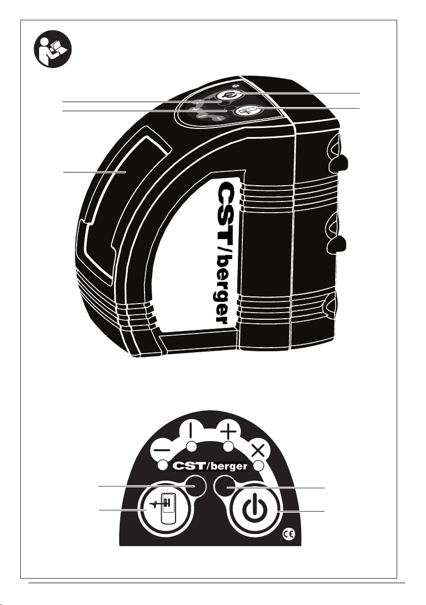
fCet appareil de mesure est fourni avec une
plaque d’avertissement en langue anglaise
(dans la représentation de l’appareil de
mesure se trouvant sur la page des graphi-
ques elle est marquée du numéro 7).
fAvant la première mise en service, recouvrir
le texte anglais de la plaque d’avertissement
par l’autocollant fourni dans votre langue.
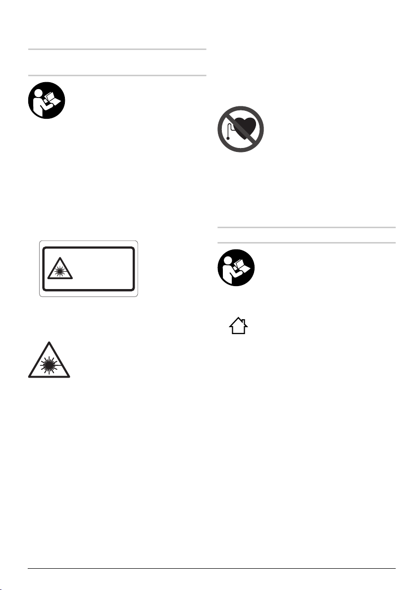
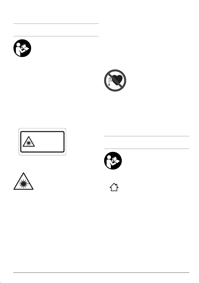
Ne pas diriger le faisceau laser
vers des personnes ou des ani-
maux et ne jamais regarder soi-
même dans le faisceau laser. Cet
appareil de mesure génère un rayonne-
ment laser de la classe 2M selon la
norme IEC 60825-1. Regarder directe-
ment dans le faisceau laser –surtout
avec des instruments d’optique de
focalisation tels que jumelles etc. –
peut endommager les yeux.
fNe pas utiliser les lunettes de vision du fais-
ceau laser en tant que lunettes de protec-
tion. Les lunettes de vision du faisceau laser
servent à mieux visualiser le faisceau laser, elles ne
protègent cependant pas du rayonnement laser.
fNe pas utiliser les lunettes de vision du fais-
ceau laser en tant que lunettes de soleil ou
en circulation routière. Les lunettes de vision
du faisceau laser ne protègent pas parfaitement
contre les rayons ultra-violets et réduisent la per-
ception des couleurs.
fNe faire réparer l’appareil de mesure que par
une personne qualifiée et seulement avec
des pièces de rechange d’origine. Ceci permet
d’assurer la sécurité de l’appareil de mesure.
fNe pas laisser les enfants utiliser l’appareil
de mesure laser sans surveillance. Ils risque-
raient d’éblouir d’autres personnes par mégarde.
fNe pas faire fonctionner les appareils de
mesure en atmosphère explosive, par exem-
ple en présence de liquides inflammables,
de gaz ou de poussières. L’appareil de mesure
produit des étincelles qui peuvent enflammer les
poussières ou les vapeurs.
Ne pas placer le mini-trépied laser
à proximité de stimulateurs car-
diaques. Les aimants 13 génèrent un
champ pouvant entraver le fonctionne-
ment de stimulateurs cardiaques.
fGarder le mini-trépied laser à distance des
supports de données magnétiques et
d’appareils sensibles aux sources magnéti-
ques. L’effet des aimants 13 peut entraîner des
pertes de donnés irréversibles.
fProduit destiné à un usage professionnel
présentant des dangers pour une autre utili-
sation que la prise de niveau.
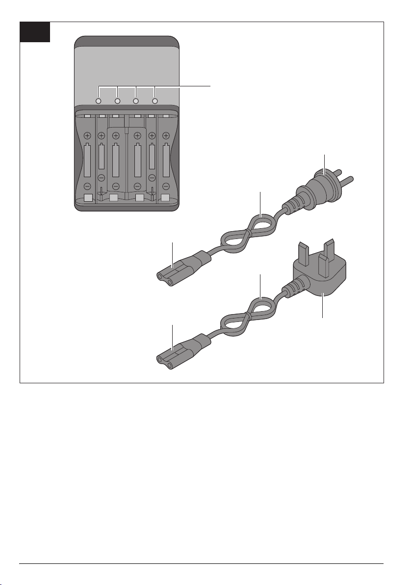
Instructions de sécurité pour
chargeurs
Il est impératif de lire toutes les
consignes de sécurité et toutes les
instructions. Le non respect des consi-
gnes de sécurité et instructions indi-
quées ci-après peut entraîner un choc
électrique, un incendie et/ou une bles-
sure sérieuse sur les personnes.
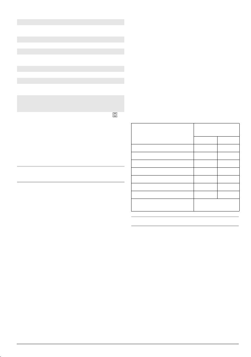
Ne pas exposer le chargeur à la pluie
ou à l’humidité. La pénétration d’eau
dans un chargeur augmente le risque d’un
choc électrique.
fNe pas charger des accus d’une autre mar-
que. Le chargeur n’est approprié que pour char-
ger des accus CST/berger (NiMH) des tensions
indiquées dans les Caractéristiques Techniques.
Sinon, il y a risque d’incendie et d’explosion.
fMaintenir le chargeur propre. Un encrasse-
ment augmente le risque de choc électrique.
IEC 60825-1:2007-03
< 1 mW, 635 nm
Rayonnement laser classe 2M
Ne pas regarder dans le fais-
ceau ni à l’oeil nu ni à l’aide
d’un instrument d’optique.
OBJ_BUCH-931-004.book Page 19 Friday, August 14, 2009 12:12 PM

20 | Français 2 610 A15 118 • 14.8.09
fAvant toute utilisation, contrôler le chargeur,
la fiche et le câble. Ne pas utiliser le char-
geur si des défauts sont constatés. Ne pas
démonter le chargeur soi-même et ne le faire
réparer que par une personne qualifiée et
seulement avec des pièces de rechange
d’origine. Des chargeurs, câbles et fiches
endommagés augmentent le risque d’un choc
électrique.
fNe pas utiliser le chargeur sur un support
facilement inflammable (tel que papier, tex-
tiles etc.) ou dans un environnement inflam-
mable. L’échauffement du chargeur lors du
processus de charge augmente le risque d’incen-
die.
fDans de mauvaises conditions, du liquide
peut être éjecté de la batterie ; éviter tout
contact. En cas de contact accidentel, net-
toyer à l’eau. Si le liquide entre en contact
avec les yeux, rechercher en plus une aide
médicale. Le liquide éjecté des batteries peut
causer des irritations ou des brûlures.
fSurveillez les enfants et assurez-vous qu’ils
ne jouent pas avec le chargeur.
Description du
fonctionnement
Utilisation conforme
Laser croix
L’appareil de mesure est conçu pour déterminer et
vérifier des lignes horizontales et verticales.
Chargeur
N’utilisez le chargeur que lorsque vous vous êtes fami-
liarisés avec toutes ses fonctions et êtes capable de
l’utiliser sans réserves ou après avoir reçu des instruc-
tions correspondantes.
Eléments de l’appareil
La numérotation des éléments de l’appareil se réfère
à la représentation de l’appareil de mesure sur la page
graphique.
Laser croix
1Orifice de sortie du faisceau laser
2LED mode de fonctionnement intérieur/extérieur
3LED du mode de service
4Touche de service
5Commutateur mode de fonctionnement inté-
rieur/extérieur
6Compartiment à piles
7Plaque signalétique du laser
Mini-trépied laser*
8Filetage 1/4" x 20
9Plaque de montage orientable
10 Molettes de réglage
11 Pieds de trépied pliants
12 Filetage 5/8" x 11
13 Aimant de fixation
Chargeur
14 Voyant indiquant l’état de charge de l’accu
15 Câble du chargeur
16 Fiche de l’appareil
17 Fiche de secteur
*Les accessoires décrits ou illustrés ne sont pas tous
compris dans la fourniture. Vous trouverez les acces-
soires complets dans notre programme d’accessoires.
OBJ_BUCH-931-004.book Page 20 Friday, August 14, 2009 12:12 PM
This manual suits for next models
2
Table of contents
Languages:
Other CST/BERGER Measuring Instrument manuals

CST/BERGER
CST/BERGER LD90 User manual

CST/BERGER
CST/BERGER LASERMARK GIZLT-3 User manual

CST/BERGER
CST/BERGER 56-DGT2 User manual

CST/BERGER
CST/BERGER LMH600 User manual

CST/BERGER
CST/BERGER Lasermark LD500 User manual

CST/BERGER
CST/BERGER RL25H User manual

CST/BERGER
CST/BERGER CST202 User manual

CST/BERGER
CST/BERGER LMPL20 User manual

CST/BERGER
CST/BERGER Lasermark LD500 User manual

CST/BERGER
CST/BERGER LM30 User manual